EP0693275A1 - Vorfuss-Entlastungsschuh - Google Patents
Vorfuss-Entlastungsschuh Download PDFInfo
- Publication number
- EP0693275A1 EP0693275A1 EP94112190A EP94112190A EP0693275A1 EP 0693275 A1 EP0693275 A1 EP 0693275A1 EP 94112190 A EP94112190 A EP 94112190A EP 94112190 A EP94112190 A EP 94112190A EP 0693275 A1 EP0693275 A1 EP 0693275A1
- Authority
- EP
- European Patent Office
- Prior art keywords
- supports
- shoe according
- relief shoe
- forefoot
- sole
- Prior art date
- Legal status (The legal status is an assumption and is not a legal conclusion. Google has not performed a legal analysis and makes no representation as to the accuracy of the status listed.)
- Granted
Links
- 210000004744 fore-foot Anatomy 0.000 title claims description 24
- 239000000463 material Substances 0.000 claims description 8
- 210000000452 mid-foot Anatomy 0.000 claims description 4
- 210000002683 foot Anatomy 0.000 claims description 3
- 230000003247 decreasing effect Effects 0.000 claims description 2
- 238000005096 rolling process Methods 0.000 description 5
- 230000035939 shock Effects 0.000 description 3
- 238000010521 absorption reaction Methods 0.000 description 2
- 238000011161 development Methods 0.000 description 2
- 230000018109 developmental process Effects 0.000 description 2
- 210000003371 toe Anatomy 0.000 description 2
- 206010061159 Foot deformity Diseases 0.000 description 1
- 208000001963 Hallux Valgus Diseases 0.000 description 1
- 238000010276 construction Methods 0.000 description 1
- 238000010586 diagram Methods 0.000 description 1
- 239000004744 fabric Substances 0.000 description 1
- 239000006260 foam Substances 0.000 description 1
- 230000005021 gait Effects 0.000 description 1
- 210000004394 hip joint Anatomy 0.000 description 1
- 239000010985 leather Substances 0.000 description 1
- 239000004033 plastic Substances 0.000 description 1
- 230000002980 postoperative effect Effects 0.000 description 1
- 239000007779 soft material Substances 0.000 description 1
- 238000011477 surgical intervention Methods 0.000 description 1
- 239000004753 textile Substances 0.000 description 1
Images

Classifications
-
- A—HUMAN NECESSITIES
- A61—MEDICAL OR VETERINARY SCIENCE; HYGIENE
- A61F—FILTERS IMPLANTABLE INTO BLOOD VESSELS; PROSTHESES; DEVICES PROVIDING PATENCY TO, OR PREVENTING COLLAPSING OF, TUBULAR STRUCTURES OF THE BODY, e.g. STENTS; ORTHOPAEDIC, NURSING OR CONTRACEPTIVE DEVICES; FOMENTATION; TREATMENT OR PROTECTION OF EYES OR EARS; BANDAGES, DRESSINGS OR ABSORBENT PADS; FIRST-AID KITS
- A61F13/00—Bandages or dressings; Absorbent pads
- A61F13/04—Plaster of Paris bandages; Other stiffening bandages
- A61F13/041—Accessories for stiffening bandages, e.g. cast liners, heel-pieces
- A61F13/043—Shoe-like cast covers; Cast socks
-
- A—HUMAN NECESSITIES
- A61—MEDICAL OR VETERINARY SCIENCE; HYGIENE
- A61F—FILTERS IMPLANTABLE INTO BLOOD VESSELS; PROSTHESES; DEVICES PROVIDING PATENCY TO, OR PREVENTING COLLAPSING OF, TUBULAR STRUCTURES OF THE BODY, e.g. STENTS; ORTHOPAEDIC, NURSING OR CONTRACEPTIVE DEVICES; FOMENTATION; TREATMENT OR PROTECTION OF EYES OR EARS; BANDAGES, DRESSINGS OR ABSORBENT PADS; FIRST-AID KITS
- A61F5/00—Orthopaedic methods or devices for non-surgical treatment of bones or joints; Nursing devices ; Anti-rape devices
- A61F5/01—Orthopaedic devices, e.g. long-term immobilising or pressure directing devices for treating broken or deformed bones such as splints, casts or braces
- A61F5/0195—Shoe-like orthopaedic devices for protecting the feet against injuries after operations
Definitions
- the invention relates to a forefoot relief shoe with a substantially triangular sole part with a decreasing thickness in a side view or a vertical longitudinal cross section, which ends at the front in front of the midfoot region of the wearer.
- Surgical interventions in the forefoot area require postoperative protection of the forefoot (which is not yet resilient). If the patient does not want to walk on crutches during this time, the relief shoe mentioned at the beginning offers itself, the inclined footbed in conjunction with the sole part ending in front of the midfoot area ensures that the patient can walk without forefoot and can also roll safely.
- the shoe according to the US patent mentioned has a compressible sole with a compressibility that increases from the back to the front. This configuration is intended to better absorb shocks in the front area of the shoe.
- the forefoot relief shoe with the features described in claim 1.
- the sole part has a hollow profile with in essential vertical supports for connecting the full-surface base and the full-surface upper body adjacent to the footbed.
- the supports have an increasing diameter or an increasing horizontal cross section at least in the central region in the longitudinal axial direction towards the base. It has been found that a homogeneous block of sole or foam block is unsuitable for the roll-off function, since excessive thrust forces are thereby transmitted to the hip joint. Shear and rolling forces act on the sole part in a semi-elastic manner, which only guarantee a sufficient or improved lifespan of the forefoot relief shoe with a given horizontal elasticity. This goal is taken into account by the combination of features according to claim 1.
- the supports preferably have a frustoconical shape, i.e. H. they widen conically downwards.
- the central longitudinal axis of the individual supports is inclined to the rear by an angle between 10 ° and 20 °, i. H. approximately at an angle that the supports are substantially perpendicular relative to the footbed of the relief shoe or its upper part of the sole part.
- the longitudinal axis of this upper body (or the footbed) is inclined by 5 ° to 15 ° with respect to the horizontal or the base.
- the front end wall is bent in an S-shape in a longitudinal cross-sectional view.
- the support adjoining the front end wall has a constant cross section over its entire length (from top to bottom). This takes into account the fact that the greatest susceptibility to breakage of the relief shoe was approximately in the middle part of the sole part, so that it is not necessary to reinforce the supports downwards in the front area.
- the supports preferably extend over the entire respective full width of the sole, ie from side wall to side wall, as a result of which they separate individual cavities lying one behind the other as transverse walls.
- the hollow profile designed in this way is more permanently elastic, saves material and is accordingly lighter than a full profile.
- the choice of material and / or geometric design of the supports means that the elasticity (softness) is to the rear, ie. H. increasingly trained towards the heel area. Due to the soft adjustment of the rear part, the heel tread creates a decrease in cushioning towards the unwind, which takes into account the fact that a high stability is required when unrolling in the front part. This advantageously ensures that the toes are more protected from contact with the ground when rolling off than with a full profile.
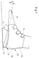
- the forefoot relief shoe 10 consists essentially of a sole part 11, optionally an intermediate piece or upper body 12, which can be part of a footbed 13, and a part consisting of two shells 14 connected to the upper body or footbed, which are closed, for example, by Velcro fasteners 15 can.
- the shells 14 can consist of leather, plastic or textile fabric.
- the forefoot relief shoe is shaped so that the forefoot 16 is exposed and is raised towards the tip of the foot, which is caused by the substantially triangular contour of the sole part 11.
- the angle of inclination ⁇ is regularly between 5 ° and 15 °.
- the footbed 13 ends with its front point 17 in front of the midfoot area, which should not be loaded.
- the wearer of the relief shoe 10 can first put the shoe on in the area of the heel 18 and roll it forward without having to run the risk of having the forefoot or toes on the ground to touch.
- the sole part 11 is not designed as a homogeneous body, but instead has a honeycomb-like hollow profile structure with vertical supports 19 to 23. At least in the central region, ie. H. In the area of the perpendicular 25, the supports 20, 21, 22 and 23 are designed such that they have an increasing diameter or an increasing horizontal cross section in the longitudinal axial direction towards the base 26. The increase in cross section from the upper body 12 to the base 26 increases the service life of the sole part 11 because the shear forces 27 and the rolling forces 28 can each be countered by greater elasticity. Forces P acting on the footbed under index 1 are divided according to the force parallelogram into feed forces P under index X and vertically downward forces P under index G.
- the flexibility of the sole part 11 is increased in the area of greater thrust or rolling forces or the material in the areas near the ground is reinforced by the supports for absorbing the vertical forces.
- the front support 19 can be made uniformly thick or wide over its length, since near the forefoot the forces - unlike in the heel area - are lower.
- the front end wall 29 is bent in an S-shape.
- a harder material is used above the diagonal plane 30, ie a material with a large spring constant and a soft material with a smaller one in the area below Spring constants used.
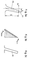
- the support 20 is inclined to the rear in a manner corresponding to the other supports 19 to 23, its longitudinal axis 31 forming an angle ⁇ between 10 ° and 20 ° with a vertical.
- the cross section of the support is also increased in a corresponding manner. Where the attacking torques are smaller, namely near the forefoot area, the design according to FIG. 3c can be selected.
Landscapes
- Health & Medical Sciences (AREA)
- Vascular Medicine (AREA)
- Engineering & Computer Science (AREA)
- Biomedical Technology (AREA)
- Heart & Thoracic Surgery (AREA)
- Life Sciences & Earth Sciences (AREA)
- Animal Behavior & Ethology (AREA)
- General Health & Medical Sciences (AREA)
- Public Health (AREA)
- Veterinary Medicine (AREA)
- Orthopedic Medicine & Surgery (AREA)
- Nursing (AREA)
- Footwear And Its Accessory, Manufacturing Method And Apparatuses (AREA)
Abstract
Description
- Die Erfindung betrifft einen Vorfuß-Entlastungsschuh mit einem in einer Seitenansicht oder einem vertikalen Längsquerschnitt im wesentlichen dreieckigen Sohlenteil mit nach hinten abnehmender Dicke, das vorn vor dem Mittelfußbereich des Trägers endet.
- Ein solcher Vorfuß-Entlastungsschuh ist aus der US-A 45 46 557 bekannt.
- Chirurgische Eingriffe im Vorfußbereich, insbesondere bei Hallux valgus-Operationen erfordern eine postoperative Schonung des (noch) nicht belastbaren Vorderfußes. Will der Patient während dieser Zeit nicht auf Krücken laufen, bietet sich der eingangs genannte Entlastungsschuh an, dessen schräggestelltes Fußbett in Verbindung mit dem vor dem Mittelfußbereich endenden Sohlenteil sicherstellt, daß der Patient ohne Vorfußbelastung auftreten und auch gefahrlos abrollen kann. Der Schuh nach der genannten US-Patentschrift besitzt eine kompressible Sohle mit einer von hinten nach vorne wachsenden Kompressibilität. Diese Ausgestaltung soll dazu dienen, Stöße im Vorderbereich des Schuhs besser absorbieren zu können.
- Es ist Aufgabe der vorliegenden Erfindung, den Schuh dahingehend weiterzuentwickeln, daß er ohne Schädigung des Laufblockes längere Tragzeiten bzw. Benutzungszeiten ermöglicht. Hierbei soll ein möglichst guter Tragkomfort sichergestellt sein.
- Diese Aufgabe wird durch den Vorfuß-Entlastungsschuh mit den im Anspruch 1 beschriebenen Merkmalen gelöst. Erfindungsgemäß besitzt dessen Sohlenteil ein Hohlprofil mit im wesentlichen vertikalen Stützen zur Verbindung der vollflächig ausgebildeten Basis und dem vollflächigen, an das Fußbett angrenzenden Oberkörper. Die Stützen weisen zumindest im mittleren Bereich in längsaxialer Richtung zur Basis hin einen zunehmenden Durchmesser oder einen zunehmenden Horizontalquerschnitt auf. Es hat sich herausgestellt, daß ein homogener Sohlenteilblock bzw. Schaumblock für die Abrollfunktion ungeeignet ist, da hierdurch zu große Schubkräfte auf das Hüftgelenk übertragen werden. Auf das Sohlenteil wirken halbelastisch Schub- und Abrollkräfte, die nur bei gegebener Horizontalelastizität eine ausreichende bzw. verbesserte Lebensdauer des Vorfußentlastungsschuhs gewährleisten. Diesem Ziel wird durch die Merkmalskombination nach Anspruch 1 Rechnung getragen.
- Weiterbildungen der Erfindung sind in den Ansprüchen 2 bis 9 beschrieben. So weisen die Stützen vorzugsweise eine Zylinderstumpfform auf, d. h. sie verbreitern sich nach unten hin konisch. Die Mittellängsachse der einzelnen Stützen ist um einen Winkel zwischen 10° und 20° nach hinten geneigt, d. h. etwa in einem Winkel, daß die Stützen relativ zum Fußbett des Entlastungsschuhs bzw. dessen Sohlenteil-Oberkörper im wesentlichen senkrecht stehen. Die Längsachse dieses Oberkörpers (bzw. des Fußbettes) ist um 5° bis 15° gegenüber der Horizontalen oder der Basis geneigt.
- Zur Verbesserung der Stoßabsorption ist die vordere Abschlußwand in einer Längsquerschnittansicht S-förmig gebogen. Die an die vordere Abschlußwand angrenzende Stütze besitzt nach einer weiteren Ausgestaltung der Erfindung über ihre gesamte Länge einen gleichbleibenden Querschnitt (von oben nach unten). Hiermit wird dem Umstand Rechnung getragen, daß die größte Bruchanfälligkeit des Entlastungsschuhs etwa im mittleren Teil des Sohlenteils bestanden hat, so daß eine Verstärkung der Stützen nach unten hin im Vorderbereich nicht erforderlich ist. Vorzugsweise erstrecken sich die Stützen über die gesamte jeweilige volle Breite der Sohle, d. h. von Seitenwand zu Seitenwand, wodurch sie als Querwände einzelne hintereinanderliegende Hohlräume voneinander abtrennen. Das so gestaltete Hohlraumprofil ist gegenüber einem Vollprofil dauerelastischer, materialsparend und dementsprechend leichter.
- Um die Gangabwicklung des Trägers vom Zeitpunkt der Fersenberührung bis zur vorderen Abrollkante physiologisch besser zu gestalten, ist nach einer weiteren Ausgestaltung der Erfindung durch Wahl des Materials und/oder geometrische Ausbildung der Stützen die Elastizität (Weichheit) nach hinten, d. h. zum Fersenbereich zunehmend ausgebildet. Durch die Weicheinstellung des hinteren Teils entsteht beim Fersenauftritt eine zur Abrollung hin abnehmende Dämpfung, wodurch berücksichtigt wird, daß bei der Abrollung im vorderen Teil eine hohe Stabilität benötigt wird. Hierdurch wird vorteilhafterweise gewährleistet, daß die Zehen beim Abrollen weitergehend als bei einem Vollprofil vor einem Bodenkontakt geschützt sind.
- Vorzugsweise liegt oberhalb einer von dem vorderen Sohlenfußpunkt zur Oberkante des hinteren Sohlenendes verlaufenden Diagonalebene ein härteres Material als unterhalb dieser Ebene vor.
- Ein Ausführungsbeispiel der Erfindung ist in den Zeichnungen dargestellt. Es zeigen
- Fig. 1
- eine schematische Seitenansicht eines Vorfuß-Entlastungsschuhs,
- Fig. 2
- eine Detailansicht dieses Entlastungsschuhs im Bereich des Sohlenteils,
- Fig. 3a u. 3c
- jeweils eine Stütze entsprechend der Ausgestaltung nach Fig. 2 und
- Fig. 3b
- ein Drehmomentdiagramm entlang der Längsachse der Stütze nach Fig. 3a.
- Der Vorfußentlastungsschuh 10 besteht im wesentlichen aus einem Sohlenteil 11, gegebenenfalls einem Zwischenstück oder Oberkörper 12, der Teil eines Fußbettes 13 sein kann, sowie einem aus zwei mit dem Oberkörper bzw. dem Fußbett verbundenen Schalen 14 bestehenden Teil, die beispielsweise über Klettverschlüsse 15 verschlossen werden können. Die Schalen 14 können aus Leder, Kunststoff oder Textilgewebe bestehen. Der Vorfuß-Entlastungsschuh ist so geformt, daß der Vorfuß 16 frei liegt und zur Fußspitze hin angehoben wird, was durch die im wesentlichen dreieckige Kontur des Sohlenteils 11 bewirkt wird. Der Neigungswinkel α liegt regelmäßig zwischen 5° und 15°. Das Fußbett 13 endet mit seinem vorderen Punkt 17 vor dem Mittelfußbereich, der nicht belastet werden soll. Beim Gehen kann der Träger des Entlastungsschuhs 10 zunächst im Bereich der Ferse 18 den Schuh aufsetzen und nach vorne hin abrollen, ohne Gefahr laufen zu müssen, mit dem Vorfuß bzw. den Zehen den Boden zu berühren.
- Anders als in Ausführungsformen nach dem Stand der Technik ist jedoch das Sohlenteil 11 nicht als homogener Körper ausgebildet, sondern besitzt eine wabenartige Hohlprofilstruktur mit vertikalen Stützen 19 bis 23. Zumindest im mittleren Bereich, d. h. im Bereich der Mittelsenkrechten 25, sind die Stützen 20, 21, 22 und 23 so ausgebildet, daß sie in längsaxialer Richtung zur Basis 26 hin einen zunehmenden Durchmesser bzw. einen zunehmenden Horizontalflächenquerschnitt aufweisen. Die Querschnittszunahme von dem Oberkörper 12 bis zur Basis 26 erhöht die Lebensdauer des Sohlenteils 11, weil den Schubkräften 27 und den Abrollkräften 28 jeweils eine größere Elastizität entgegengesetzt werden kann. Auf das Fußbett wirkende Kräfte P unter Index 1 teilen sich entsprechend dem Kraftparallelogramm in Vorschubkräfte P unter Index X und vertikal nach unten wirkende Kräfte P unter Index G auf. Durch die erfindungsgemäße Konstruktion wird die Nachgiebigkeit des Sohlenteils 11 im Bereich größerer Schub bzw. Abrollkräfte erhöht bzw. das Material in bodennahen Bereichen zur Aufnahme der Vertikalkräfte durch die Stützen verstärkt. Die vordere Stütze 19 kann über ihre Länge gesehen gleichmäßig dick bzw. breit ausgeführt sein, da nahe dem Vorfuß die Kräfte - anders als im Fersenbereich - geringer sind. Zur Stoßdämpfung und besseren Nachgiebigkeit ist die vordere Abschlußwand 29 S-förmig gebogen.
- Zur Erhöhung des Lauf- bzw. Tragekomforts wird oberhalb der Diagonalebene 30 ein härteres Material, d. h. ein Material mit einer großen Federkonstanten und im darunter liegenden Bereich ein weiches Material mit einer kleineren Federkonstanten verwendet.
- Wie aus Fig. 3a ersichtlich, ist die Stütze 20 in entsprechender Weise wie die übrigen Stützen 19 bis 23 nach hinten geneigt, wobei deren Längsachse 31 mit einer Vertikalen einen Winkel β zwischen 10° und 20° bildet. Die entlang der Stütze wirkenden Drehmomente, die sich entsprechend der Beziehung

Claims (9)
- Vorfuß-Entlastungsschuh (10) mit einem in einer Seitenansicht oder einem vertikalen Längsquerschnitt im wesentlichen dreieckigen Sohlenteil (11) mit nach hinten abnehmender Dicke, das vorn vor dem Mittelfußbereich des Trägers endet, dadurch gekennzeichnet, daß das Sohlenteil (11) ein Hohlprofil mit im wesentlichen vertikalen Stützen (19 bis 23) zur Verbindung der vollflächig ausgebildeten Basis (26) und dem vollflächigen, an das Fußbett (13) angrenzenden Oberkörper (12) ist und daß die Stützen (19 bis 23) zumindest im mittleren Bereich in längsaxialer Richtung zur Basis (26) hin einen zunehmenden Durchmesser oder einen zunehmenden Horizontalflächenquerschnitt aufweisen.
- Vorfuß-Entlastungsschuh nach Anspruch 1, dadurch gekennzeichnet, daß die Stützen (19 bis 23) eine Zylinderstumpfform aufweisen.
- Vorfuß-Entlastungsschuh nach Anspruch 1 oder 2, dadurch gekennzeichnet, daß die Mittellängsachse (31) der Stützen (20) um einen Winkel β zwischen 10° bis 20° nach hinten geneigt ist.
- Vorfuß-Entlastungsschuh nach einem der Ansprüche 1 bis 3, dadurch gekennzeichnet, daß die Längsachse des Oberkörpers (12) um α 5° bis 15° gegenüber der Horizontalen oder der Basis (26) geneigt ist.
- Vorfuß-Entlastungsschuh nach einem der Ansprüche 1 bis 4, dadurch gekennzeichnet, daß die vordere Abschlußwand (29) in einer Längsquerschnittansicht S-förmig gebogen ist.
- Vorfuß-Entlastungsschuh nach einem der Ansprüche 1 bis 5, dadurch gekennzeichnet, daß die an die vordere Abschlußwand (29) angrenzende Stütze (19) einen über ihre gesamte Länge gleichbleibenden Querschnitt aufweist.
- Vorfuß-Entlastungsschuh nach einem der Ansprüche 1 bis 6, dadurch gekennzeichnet, daß sich die Stützen (19 bis 23) über die gesamte jeweilige volle Breite der Sohle (11) erstrecken.
- Vorfuß-Entlastungsschuh nach einem der Ansprüche 1 bis 7, dadurch gekennzeichnet, daß durch Wahl des Materials und/oder durch geometrische Ausbildung der Stützen (19 bis 23) die Elastizität (Weichheit) nach hinten, d. h. zum Fersenbereich (18), zunimmt.
- Vorfuß-Entlastungsschuh nach Anspruch 8, dadurch gekenzeichnet, daß oberhalb einer von dem vorderen Sohlenfußpunkt (32) zur Oberkante (33) des hinteren Sohlendes verlaufenden Diagonalebene (30) ein härteres Material als unterhalb dieser Ebene (30) vorliegt.
Applications Claiming Priority (2)
| Application Number | Priority Date | Filing Date | Title |
|---|---|---|---|
| DE9411782U | 1994-07-21 | ||
| DE9411782U DE9411782U1 (de) | 1994-07-21 | 1994-07-21 | Vorfuß-Entlastungsschuh |
Publications (2)
| Publication Number | Publication Date |
|---|---|
| EP0693275A1 true EP0693275A1 (de) | 1996-01-24 |
| EP0693275B1 EP0693275B1 (de) | 1998-04-22 |
Family
ID=6911422
Family Applications (1)
| Application Number | Title | Priority Date | Filing Date |
|---|---|---|---|
| EP94112190A Expired - Lifetime EP0693275B1 (de) | 1994-07-21 | 1994-08-04 | Vorfuss-Entlastungsschuh |
Country Status (8)
| Country | Link |
|---|---|
| US (1) | US5537764A (de) |
| EP (1) | EP0693275B1 (de) |
| CN (1) | CN1118685A (de) |
| AT (1) | ATE165232T1 (de) |
| CA (1) | CA2145271A1 (de) |
| CZ (1) | CZ280929B6 (de) |
| DE (2) | DE9411782U1 (de) |
| HU (1) | HUT72264A (de) |
Families Citing this family (13)
| Publication number | Priority date | Publication date | Assignee | Title |
|---|---|---|---|---|
| DE29506925U1 (de) * | 1995-04-25 | 1995-07-13 | Heil- und Hilfsmittel Vertriebs-GmbH, 21377 Scharnebeck | Vorfuß-Entlastungsschuh, insbesondere zur postoperativen Behandlung |
| US6393731B1 (en) | 2001-06-04 | 2002-05-28 | Vonter Moua | Impact absorber for a shoe |
| US7004918B2 (en) * | 2002-05-23 | 2006-02-28 | Michael Alan Rolnick | Low cost orthosis for toe injuries |
| US20050223597A1 (en) * | 2002-05-23 | 2005-10-13 | Rolnick Michael A | Low cost orthosis for toe injuries |
| US6962011B2 (en) * | 2003-09-24 | 2005-11-08 | Denis Burke Drennan | Shoe for a casted foot |
| US8870876B2 (en) | 2009-02-13 | 2014-10-28 | Tarsus Medical Inc. | Methods and devices for treating hallux valgus |
| US9682003B2 (en) * | 2009-03-31 | 2017-06-20 | Prasad Gourineni | Achilles stretching devices and methods performed therewith |
| US8277459B2 (en) | 2009-09-25 | 2012-10-02 | Tarsus Medical Inc. | Methods and devices for treating a structural bone and joint deformity |
| US8652141B2 (en) | 2010-01-21 | 2014-02-18 | Tarsus Medical Inc. | Methods and devices for treating hallux valgus |
| US9125453B2 (en) | 2010-05-28 | 2015-09-08 | K-Swiss Inc. | Shoe outsole having tubes |
| US8696719B2 (en) | 2010-06-03 | 2014-04-15 | Tarsus Medical Inc. | Methods and devices for treating hallux valgus |
| DE102011121773B4 (de) | 2011-12-21 | 2016-06-09 | Christine Huber-Morawietz | Fußabschnittsentlastungsschuh mit Signalgeber |
| US8402678B1 (en) | 2012-07-19 | 2013-03-26 | Jeff Kopelman. L.L.C. | Orthopedic shoe/boot for use with foot wounds and for post op ambulation |
Citations (4)
| Publication number | Priority date | Publication date | Assignee | Title |
|---|---|---|---|---|
| US3847147A (en) * | 1973-04-25 | 1974-11-12 | R Turner | Foot support |
| US4546557A (en) * | 1981-10-09 | 1985-10-15 | Etablissements Mayzaud Maurice | Shoe, more especially for patients having undergone a surgical operation on the fore-foot |
| EP0248964A1 (de) * | 1986-06-09 | 1987-12-16 | Louis Samuel Barouk | Schuh mit Absatzstütze und mit minimalem Kontakt im Bereich des Vorderfusses, insbesondere zum Gebrauch nach einer Operation oder Verletzung |
| WO1992008382A1 (en) * | 1990-11-13 | 1992-05-29 | Darco International, Inc. | Post-operative shoes for use after forefoot surgery |
Family Cites Families (8)
| Publication number | Priority date | Publication date | Assignee | Title |
|---|---|---|---|---|
| US3061951A (en) * | 1961-05-18 | 1962-11-06 | Edward R Barron | Blast attenuating footwear |
| DE2231435A1 (de) * | 1971-08-10 | 1973-03-01 | Hideru Nakamoto | Fussbekleidung |
| JPS5429946Y2 (de) * | 1975-05-01 | 1979-09-21 | ||
| FR2489103A1 (fr) * | 1980-08-26 | 1982-03-05 | Pasquier Groupe Gep | Procede de montage d'un article chaussant tel que nu-pieds ou sandales et article chaussant obtenu |
| US4567678A (en) * | 1980-12-09 | 1986-02-04 | Morgan R Dean | Orthopedic shoe |
| GB2210559B (en) * | 1987-10-06 | 1991-08-14 | Christopher Emerick Benedict | Preformed walking cast insert and casts employing such devices |
| US5078128A (en) * | 1990-06-27 | 1992-01-07 | Royce Medical Company | Removable leg walker |
| US5088481A (en) * | 1990-10-10 | 1992-02-18 | Darco International Inc. | Casted foot medical boot with dual pivot points |
-
1994
- 1994-07-21 DE DE9411782U patent/DE9411782U1/de not_active Expired - Lifetime
- 1994-08-04 AT AT94112190T patent/ATE165232T1/de not_active IP Right Cessation
- 1994-08-04 DE DE59405798T patent/DE59405798D1/de not_active Expired - Fee Related
- 1994-08-04 EP EP94112190A patent/EP0693275B1/de not_active Expired - Lifetime
- 1994-10-21 CZ CZ942605A patent/CZ280929B6/cs not_active IP Right Cessation
- 1994-10-21 HU HU9403035A patent/HUT72264A/hu unknown
- 1994-10-25 US US08/328,877 patent/US5537764A/en not_active Expired - Fee Related
- 1994-11-19 CN CN94118722A patent/CN1118685A/zh active Pending
-
1995
- 1995-03-22 CA CA002145271A patent/CA2145271A1/en not_active Abandoned
Patent Citations (4)
| Publication number | Priority date | Publication date | Assignee | Title |
|---|---|---|---|---|
| US3847147A (en) * | 1973-04-25 | 1974-11-12 | R Turner | Foot support |
| US4546557A (en) * | 1981-10-09 | 1985-10-15 | Etablissements Mayzaud Maurice | Shoe, more especially for patients having undergone a surgical operation on the fore-foot |
| EP0248964A1 (de) * | 1986-06-09 | 1987-12-16 | Louis Samuel Barouk | Schuh mit Absatzstütze und mit minimalem Kontakt im Bereich des Vorderfusses, insbesondere zum Gebrauch nach einer Operation oder Verletzung |
| WO1992008382A1 (en) * | 1990-11-13 | 1992-05-29 | Darco International, Inc. | Post-operative shoes for use after forefoot surgery |
Also Published As
| Publication number | Publication date |
|---|---|
| EP0693275B1 (de) | 1998-04-22 |
| CA2145271A1 (en) | 1996-01-22 |
| HUT72264A (en) | 1996-04-29 |
| CZ260594A3 (en) | 1996-02-14 |
| CN1118685A (zh) | 1996-03-20 |
| US5537764A (en) | 1996-07-23 |
| DE59405798D1 (de) | 1998-05-28 |
| DE9411782U1 (de) | 1994-10-06 |
| CZ280929B6 (cs) | 1996-05-15 |
| ATE165232T1 (de) | 1998-05-15 |
| HU9403035D0 (en) | 1994-12-28 |
Similar Documents
| Publication | Publication Date | Title |
|---|---|---|
| DE60018351T2 (de) | Schuhsohle | |
| DE112005002327B4 (de) | Stoßabsorbierende Vorrichtung für eine Schuhsohle in einem Rückfußteil | |
| EP0373336B1 (de) | Einlage für einen Schuh | |
| DE19953147B4 (de) | Stoßabsorberstruktur für Schuhsohlen | |
| DE2752239C3 (de) | Sportschuh mit einer Gleitschutzsohle | |
| DE60030188T2 (de) | Schuhwerk | |
| EP0999764B1 (de) | Schuh | |
| EP0348424B1 (de) | Sportschuh mit elastischer fersenkappe | |
| EP0693275B1 (de) | Vorfuss-Entlastungsschuh | |
| DE3318121A1 (de) | Schuhsohle | |
| CH717157A1 (de) | Sohle für ein Laufschuh. | |
| DE102022100196A1 (de) | Sohlenstruktur und Schuhe mit einer solchen Sohlenstruktur | |
| DE69817930T2 (de) | Sportschuh mit äusserem Rahmen | |
| DE3120349A1 (de) | Golfschuhe | |
| WO2015185483A1 (de) | Schuh, insbesondere laufschuh | |
| DE3138325A1 (de) | Luftpolster-einlegesohle | |
| WO2008095726A1 (de) | Schuheinlage | |
| DE102022100194A1 (de) | Sohlenstruktur und Schuhe mit einer solchen Sohlenstruktur | |
| EP0739616B1 (de) | Vorfuss-Entlastungsschuh, insbesondere zur postoperativen Behandlung | |
| EP0591909B1 (de) | Schuh | |
| DE29818243U1 (de) | Schuhlaufwerk | |
| DE9013727U1 (de) | Sohlenkonstruktion für Schuhe aller Art | |
| WO1987006801A2 (en) | Sandal | |
| DE202008002681U1 (de) | Schuhsohle | |
| DE8216935U1 (de) | Sportschuh |
Legal Events
| Date | Code | Title | Description |
|---|---|---|---|
| PUAI | Public reference made under article 153(3) epc to a published international application that has entered the european phase |
Free format text: ORIGINAL CODE: 0009012 |
|
| 17P | Request for examination filed |
Effective date: 19941202 |
|
| AK | Designated contracting states |
Kind code of ref document: A1 Designated state(s): AT BE CH DE DK ES FR GB GR IE IT LI LU MC NL PT SE |
|
| GRAG | Despatch of communication of intention to grant |
Free format text: ORIGINAL CODE: EPIDOS AGRA |
|
| GRAG | Despatch of communication of intention to grant |
Free format text: ORIGINAL CODE: EPIDOS AGRA |
|
| GRAH | Despatch of communication of intention to grant a patent |
Free format text: ORIGINAL CODE: EPIDOS IGRA |
|
| 17Q | First examination report despatched |
Effective date: 19971006 |
|
| GRAH | Despatch of communication of intention to grant a patent |
Free format text: ORIGINAL CODE: EPIDOS IGRA |
|
| GRAA | (expected) grant |
Free format text: ORIGINAL CODE: 0009210 |
|
| RAP1 | Party data changed (applicant data changed or rights of an application transferred) |
Owner name: PODIA TRADE HEIL- UND HILFSMITTEL GMBH & CO. KG |
|
| AK | Designated contracting states |
Kind code of ref document: B1 Designated state(s): AT BE CH DE DK ES FR GB GR IE IT LI LU MC NL PT SE |
|
| PG25 | Lapsed in a contracting state [announced via postgrant information from national office to epo] |
Ref country code: NL Free format text: LAPSE BECAUSE OF FAILURE TO SUBMIT A TRANSLATION OF THE DESCRIPTION OR TO PAY THE FEE WITHIN THE PRESCRIBED TIME-LIMIT Effective date: 19980422 Ref country code: IT Free format text: LAPSE BECAUSE OF FAILURE TO SUBMIT A TRANSLATION OF THE DESCRIPTION OR TO PAY THE FEE WITHIN THE PRE;WARNING: LAPSES OF ITALIAN PATENTS WITH EFFECTIVE DATE BEFORE 2007 MAY HAVE OCCURRED AT ANY TIME BEFORE 2007. THE CORRECT EFFECTIVE DATE MAY BE DIFFERENT FROM THE ONE RECORDED.SCRIBED TIME-LIMIT Effective date: 19980422 Ref country code: GR Free format text: LAPSE BECAUSE OF FAILURE TO SUBMIT A TRANSLATION OF THE DESCRIPTION OR TO PAY THE FEE WITHIN THE PRESCRIBED TIME-LIMIT Effective date: 19980422 Ref country code: GB Free format text: LAPSE BECAUSE OF FAILURE TO SUBMIT A TRANSLATION OF THE DESCRIPTION OR TO PAY THE FEE WITHIN THE PRESCRIBED TIME-LIMIT Effective date: 19980422 Ref country code: FR Free format text: LAPSE BECAUSE OF FAILURE TO SUBMIT A TRANSLATION OF THE DESCRIPTION OR TO PAY THE FEE WITHIN THE PRESCRIBED TIME-LIMIT Effective date: 19980422 Ref country code: ES Free format text: THE PATENT HAS BEEN ANNULLED BY A DECISION OF A NATIONAL AUTHORITY Effective date: 19980422 |
|
| REF | Corresponds to: |
Ref document number: 165232 Country of ref document: AT Date of ref document: 19980515 Kind code of ref document: T |
|
| REG | Reference to a national code |
Ref country code: CH Ref legal event code: EP |
|
| REF | Corresponds to: |
Ref document number: 59405798 Country of ref document: DE Date of ref document: 19980528 |
|
| PG25 | Lapsed in a contracting state [announced via postgrant information from national office to epo] |
Ref country code: SE Free format text: LAPSE BECAUSE OF FAILURE TO SUBMIT A TRANSLATION OF THE DESCRIPTION OR TO PAY THE FEE WITHIN THE PRESCRIBED TIME-LIMIT Effective date: 19980722 Ref country code: PT Free format text: LAPSE BECAUSE OF FAILURE TO SUBMIT A TRANSLATION OF THE DESCRIPTION OR TO PAY THE FEE WITHIN THE PRESCRIBED TIME-LIMIT Effective date: 19980722 Ref country code: DK Free format text: LAPSE BECAUSE OF FAILURE TO SUBMIT A TRANSLATION OF THE DESCRIPTION OR TO PAY THE FEE WITHIN THE PRESCRIBED TIME-LIMIT Effective date: 19980722 |
|
| REG | Reference to a national code |
Ref country code: IE Ref legal event code: FG4D Free format text: 79979 |
|
| PG25 | Lapsed in a contracting state [announced via postgrant information from national office to epo] |
Ref country code: LU Free format text: LAPSE BECAUSE OF NON-PAYMENT OF DUE FEES Effective date: 19980804 Ref country code: AT Free format text: LAPSE BECAUSE OF NON-PAYMENT OF DUE FEES Effective date: 19980804 |
|
| PG25 | Lapsed in a contracting state [announced via postgrant information from national office to epo] |
Ref country code: LI Free format text: LAPSE BECAUSE OF NON-PAYMENT OF DUE FEES Effective date: 19980831 Ref country code: CH Free format text: LAPSE BECAUSE OF NON-PAYMENT OF DUE FEES Effective date: 19980831 Ref country code: BE Free format text: LAPSE BECAUSE OF NON-PAYMENT OF DUE FEES Effective date: 19980831 |
|
| EN | Fr: translation not filed | ||
| NLV1 | Nl: lapsed or annulled due to failure to fulfill the requirements of art. 29p and 29m of the patents act | ||
| GBV | Gb: ep patent (uk) treated as always having been void in accordance with gb section 77(7)/1977 [no translation filed] |
Effective date: 19980422 |
|
| PG25 | Lapsed in a contracting state [announced via postgrant information from national office to epo] |
Ref country code: IE Free format text: LAPSE BECAUSE OF NON-PAYMENT OF DUE FEES Effective date: 19981023 |
|
| REG | Reference to a national code |
Ref country code: IE Ref legal event code: FD4D Ref document number: 79979 Country of ref document: IE |
|
| PLBE | No opposition filed within time limit |
Free format text: ORIGINAL CODE: 0009261 |
|
| STAA | Information on the status of an ep patent application or granted ep patent |
Free format text: STATUS: NO OPPOSITION FILED WITHIN TIME LIMIT |
|
| BERE | Be: lapsed |
Owner name: PODIA TRADE HEIL- UND HILFSMITTEL G.M.B.H. & CO. Effective date: 19980831 |
|
| PG25 | Lapsed in a contracting state [announced via postgrant information from national office to epo] |
Ref country code: MC Free format text: LAPSE BECAUSE OF NON-PAYMENT OF DUE FEES Effective date: 19990228 |
|
| 26N | No opposition filed | ||
| REG | Reference to a national code |
Ref country code: CH Ref legal event code: PL |
|
| PG25 | Lapsed in a contracting state [announced via postgrant information from national office to epo] |
Ref country code: DE Free format text: LAPSE BECAUSE OF NON-PAYMENT OF DUE FEES Effective date: 19990601 |