EP0693376A2 - Maschinenverkleidung, insbesondere für eine Druckmaschine und Verfahren zu deren Herstellung - Google Patents
Maschinenverkleidung, insbesondere für eine Druckmaschine und Verfahren zu deren Herstellung Download PDFInfo
- Publication number
- EP0693376A2 EP0693376A2 EP95109332A EP95109332A EP0693376A2 EP 0693376 A2 EP0693376 A2 EP 0693376A2 EP 95109332 A EP95109332 A EP 95109332A EP 95109332 A EP95109332 A EP 95109332A EP 0693376 A2 EP0693376 A2 EP 0693376A2
- Authority
- EP
- European Patent Office
- Prior art keywords
- machine
- wall
- board
- sealing element
- die
- Prior art date
- Legal status (The legal status is an assumption and is not a legal conclusion. Google has not performed a legal analysis and makes no representation as to the accuracy of the status listed.)
- Granted
Links
- 238000007639 printing Methods 0.000 title claims description 7
- 238000004519 manufacturing process Methods 0.000 title claims description 6
- 238000007789 sealing Methods 0.000 claims abstract description 19
- 238000005452 bending Methods 0.000 claims description 13
- 238000005253 cladding Methods 0.000 claims description 12
- 238000000034 method Methods 0.000 claims description 4
- 230000000994 depressogenic effect Effects 0.000 claims 1
- 239000000314 lubricant Substances 0.000 abstract description 8
- 239000002184 metal Substances 0.000 abstract description 4
- 239000000463 material Substances 0.000 abstract description 3
- 230000006870 function Effects 0.000 description 4
- BASFCYQUMIYNBI-UHFFFAOYSA-N platinum Chemical compound [Pt] BASFCYQUMIYNBI-UHFFFAOYSA-N 0.000 description 3
- 230000001681 protective effect Effects 0.000 description 3
- 238000005520 cutting process Methods 0.000 description 2
- 238000011161 development Methods 0.000 description 2
- 230000018109 developmental process Effects 0.000 description 2
- 238000005516 engineering process Methods 0.000 description 2
- 230000009993 protective function Effects 0.000 description 2
- 239000003566 sealing material Substances 0.000 description 2
- 239000007858 starting material Substances 0.000 description 2
- 238000005553 drilling Methods 0.000 description 1
- 230000008030 elimination Effects 0.000 description 1
- 238000003379 elimination reaction Methods 0.000 description 1
- 238000009413 insulation Methods 0.000 description 1
- 238000005461 lubrication Methods 0.000 description 1
- 238000003754 machining Methods 0.000 description 1
- 238000003801 milling Methods 0.000 description 1
- 238000004080 punching Methods 0.000 description 1
- 239000002994 raw material Substances 0.000 description 1
- 230000000284 resting effect Effects 0.000 description 1
Images





Classifications
-
- B—PERFORMING OPERATIONS; TRANSPORTING
- B41—PRINTING; LINING MACHINES; TYPEWRITERS; STAMPS
- B41F—PRINTING MACHINES OR PRESSES
- B41F13/00—Common details of rotary presses or machines
- B41F13/0024—Frames
Definitions
- the invention relates to a machine casing, in particular for a printing unit of a printing press, which in addition to the protective function also fulfills a sealing function for machine elements supplied with lubricant.
- a machine cover of this type is known from DE-G 8 620 168.9. Clamping angles are arranged in the edge area, between which there is an elastic profile rubber. This solution is very complex and requires many individual parts.
- EP 0 417 465 A2 Another protective device for printing presses is known from EP 0 417 465 A2, in which the protective device encapsulates the printing units and consists of a sound-reducing material. If the protective device is made in several parts, sealing elements are used. A sealing function for lubricants cannot be found.
- the object of the invention is to develop a machine cover that can be produced with little effort, consists of a reduced number of parts and fulfills a reliable sealing function against lubricants.
- the machine cladding made of sheet metal consists of at least one component with at least one side wall that is plane-parallel a flange is assigned.
- a circumferential depression is made in the side wall or the flanged wall, in which a rubber is preferably arranged as the circumferential sealing material.
- the sealing material is elastic and resistant to lubricants.
- a cover is attached to the machine casing, which can also be designed as a door.
- the machine cladding reduces the manufacturing costs and, in addition to the protective function, also improves the sealing function of free spaces for accommodating machine elements that are supplied with lubricant. The reduction in manufacturing costs results in particular from the complete elimination of subsequent (after the bending processes) non-cutting or machining steps.
- the machine casing can be coated with a sound-absorbing, lubricant-resistant material.
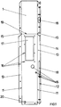
- a plate 1 is in the form of a sheet metal blank for a flat preform as the starting material for a machine cladding in FIG. 1 shown.
- the circuit board 1 has already been provided with all the necessary openings, for example in the form of notches 15, bores 16 or openings 17.
- the processing can be carried out, for example, by punching, using a laser beam or cutting tools (drills, milling cutters, etc.), which will not be discussed further.
- the circuit board 1 is processed in the method steps described below to form a component of a machine cladding which has a side wall 13, a flanged wall 14 and a circumferential depression 10 on at least one side, in which a sealing element 9, preferably an elastic circumferential rubber, is arranged.
- the openings 15 to 18 provided in the side wall 13 and the flange wall 14 are congruent one above the other, so that the machine casing or the component can be connected to an associated side frame 22.
- the manufacturing process takes place as follows: A tool known per se in forming technology, especially in sheet metal forming, is used for the angular bending of blank 1.
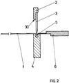
- the tool essentially consists of a punch 3 and an associated die 4.
- the punch 3 is fastened to a punch holder 2 and the die 4 has a bending die with a die profile 5 in a U-shape, which is directed in the direction of the punch 3 changes into a V-shape.
- the die 4 is assigned a movable stop 6 (FIGS. 2, 6, 9, 11) and at least one side surface of the die 4 is designed as a stop 7 (FIG. 7).
- the punch holder 2 has a surface 30 which is arranged plane-parallel to the surface of the die 4.
- the circuit board 1 is positioned against the stop 6 in such a way that the stamp 3 is above a bending line 12 of the circuit board 1 (FIG. 2).
- the stamp 3 penetrates with the circuit board 1 into the die 4, an angle is bent so that the flange wall 14 is formed (FIG. 3).
- the punch 3 is moved back out of the die 4 and moved vertically parallel to the exposed side face of the die 4, such that a face 30 of the punch holder 2 bends the flanging wall 14 along the bending line 12 plane-parallel to the plate 1 (FIGS. 4, 5).
- the stamp 3 also serves as Attack.
- the openings in the form of notches 15, bores 16 or elongated holes 18 are thus congruent.
- the board 1 resting on the die 4 is moved further against the stop 6 to the position of the intended depression 10.
- the punch 3 is moved towards the board 1 and bends the depression 10 at an angle which depends on the thickness of the board 1 and is the die shape (Fig. 6).
- the board 1 is rotated in the tool and on the back the side wall 13 is angled away from the board 1 along the bending line 11 (FIG. 1).
- One side surface of the die 4 is used as a stop 7 (FIGS. 7, 8).
- the first side of the circuit board 1 is thus produced.
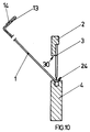
- the opposite side of the circuit board 1 is moved according to FIG. 9 against the stop 6 and in the present example the punch 3 bends the stiffening wall 24 at a right angle (FIG. 10).
- the side wall 13 is bent at right angles to the circuit board 1.
- the second side of the board 1 is finished (Fig. 13).
- the circuit board 1 is now angled at the bending lines 19 and 20 and the finished component can be connected to adjacent components 27, 28 and 29 as a cladding 8.
- the second side of the circuit board 1 can, however, also be formed after the above-mentioned method steps of the first side, namely with a side wall 13 and a flanged wall 14 and a depression 10 for receiving a sealing element 9.
- the entire machine casing can be made from a single board 1.
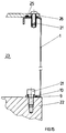
- the sealing element 9 is glued circumferentially into the depression 10, and the sealing element 9 can also be clamped between the side wall 13 and the flange wall 14.
- the machine cover, enclosing the free space 23, is fastened to a side frame 22 by means of detachable connecting elements 21.
- the sealing element 9 is thus arranged between the side frame 22 and the machine cladding or the circuit board 1 and completely seals the surroundings against lubricant occurring in the free space 23.
- the drive elements that require lubrication are generally arranged in the free space 23.
- the Machine cover arranged approximately parallel to the side frame 22, a cover 26 in which a sealing element 25 is incorporated.
- the cover 26 is connected to the machine casing or the circuit board 1 via connecting elements 21.
- the cover 26 can also be designed as a door with hinges and connecting elements.
Landscapes
- Engineering & Computer Science (AREA)
- Mechanical Engineering (AREA)
- Casings For Electric Apparatus (AREA)
- Printing Methods (AREA)
- Accessory Devices And Overall Control Thereof (AREA)
- Bending Of Plates, Rods, And Pipes (AREA)
Abstract
Description
- Die Erfindung betrifft eine Maschinenverkleidung, insbesondere für ein Druckwerk einer Druckmaschine, die neben der Schutzfunktion auch eine Dichtfunktion für mit Schmiermittel versorgte Maschinenelemente erfüllt.
- Eine Maschinenverkleidung dieser Art ist aus dem DE-G 8 620 168.9 bekannt. Im Randbereich sind Klemmwinkel angeordnet, zwischen denen sich ein elastischer Profilgummi befindet. Diese Lösung ist sehr aufwendig und benötigt viele Einzelteile.
- Eine weitere Schutzvorrichtung für Druckmaschinen ist aus der EP 0 417 465 A2 bekannt, bei der die Schutzvorrichtung die Druckwerke kapselt und aus einem schallmindernden Material besteht. Ist die Schutzvorrichtung mehrteilig ausgeführt, so werden Dichtelemente verwendet. Eine Dichtfunktion für Schmiermittel ist nicht zu entnehmen.
- Aufgabe der Erfindung ist es eine Maschinenverkleidung zu entwickeln, die mit geringem Aufwand herstellbar ist, aus verringerter Teileanzahl besteht und eine zuverlässige Dichtfunktion gegenüber Schmiermitteln erfüllt.
- Gelöst wird das durch den kennzeichnenden Teil der Patentansprüche 1 und 4. Weiterbildungen ergeben sich aus den Unteransprüchen.
- Die aus Blech gefertigte Maschinenverkleidung besteht mindestens aus einem Bauteil mit mindestens einer Seitenwand, der planparallel eine Bördelwand zugeordnet ist. In der Seitenwand oder der Bördelwand ist eine umlaufende Einsenkung eingebracht, in der vorzugsweise ein Gummi als umlaufendes Dichtmaterial angeordnet ist. Das Dichtmaterial ist elastisch und gegen Schmiermittel beständig. An der Maschinenverkleidung ist ein Deckel angebracht, der auch als Tür ausgeführt werden kann. Die Maschinenverkleidung reduziert die Herstellungskosten und verbessert neben der Schutzfunktion auch die Dichtfunktion von Freiräumen zur Aufnahme von Maschinenelementen, die mit Schmiermittel versorgt werden. Die Senkung der Herstellungskosten resultiert insbesondere durch den völligen Wegfall nachträglicher (nach den Biegevorgängen) spanloser oder spanender Fertigungsschritte. Um den Schallschutz zu erhöhen kann die Maschinenverkleidung mit einem schalldämmenden, gegen Schmiermittel beständigen Material beschichtet sein.
- Die Erfindung soll an einem Ausführungsbeispiel näher erläutert werden. Dabei zeigen:
- Fig. 1
- eine Platine als Ausgangsmaterial,
- Fig. 2
- ein Umformwerkzeug mit einer Platine,
- Fig. 3 - 12
- die Fertigungsschritte der Platine im Umformwerkzeug,
- Fig. 13
- ein umformtechnisch gefertigtes Verkleidungsteil,
- Fig. 14
- eine Verbindung des Verkleidungsteiles mit einem Seitengestell,
- Fig. 15
- eine Weiterbildung der Fig. 14 und
- Fig. 16
- die Maschinenverkleidung eines Druckwerkes.
- Eine Platine 1 ist als Blechzuschnitt einer ebenen Vorform als Ausgangsmaterial für eine Maschinenverkleidung in Fig. 1 dargestellt. Die Platine 1 ist in einer vorherigen Bearbeitungsphase bereits mit allen erforderlichen Öffnungen, z.B. in Form von Ausklinkungen 15, Bohrungen 16 oder Durchbrüchen 17 versehen worden. Die Bearbeitung kann z.B. durch Stanzen, mit Laserstrahl oder spanenden Werkzeugen (Bohrer, Fräser etc.) erfolgen, auf die nicht weiter eingegangen werden soll. Die Platine 1 wird in nachstehend beschriebenen Verfahrensschritten zu einem Bauteil einer Maschinenverkleidung verarbeitet, das an mindestens einer Seite eine Seitenwand 13, eine Bördelwand 14 sowie eine umlaufende Einsenkung 10 aufweist, in der ein Dichtelement 9, vorzugsweise ein elastischer umlaufender Gummi, angeordnet ist. Die in der Seitenwand 13 und der Bördelwand 14 vorgesehenen Öffnungen 15 bis 18 sind deckungsgleich übereinanderliegend, so daß die Maschinenverkleidung bzw. das Bauteil mit einem zugehörigen Seitengestell 22 verbunden werden kann. Der Herstellungsprozeß erfolgt wie folgt: Es wird ein in der Umformtechnik, speziell in der Blechumformung an sich bekanntes Werkzeug zum Winkelbiegen von Platine 1 verwendet. Das Werkzeug besteht gemäß Fig. 2 im wesentlichen aus einem Stempel 3 und einer zugeordneten Matrize 4. Der Stempel 3 ist an einem Stempelhalter 2 befestigt und die Matrize 4 besitzt ein Biegegesenk mit einem Matrizenprofil 5 in U-Form, welche in Richtung des Stempels 3 in eine V-Form übergeht. Weiterhin ist der Matrize 4 ein beweglicher Anschlag 6 (Fig. 2, 6, 9, 11) zugeordnet und mindestens eine Seitenfläche der Matrize 4 ist als Anschlag 7 (Fig. 7) ausgebildet. Der Stempelhalter 2 weist eine Fläche 30 auf, die planparallel zur Oberfläche der Matrize 4 angeordnet ist.
- Die Platine 1 wird gegen den Anschlag 6 positioniert, derart, daß der Stempel 3 über einer Biegelinie 12 der Platine 1 steht (Fig. 2). Der Stempel 3 dringt mit der Platine 1 in die Matrize 4 ein, ein Winkel wird gebogen, so daß die Bördelwand 14 entsteht (Fig. 3). Der Stempel 3 wird aus der Matrize 4 zurückbewegt und parallel zur freiliegenden Seitenfläche der Matrize 4 vertikal bewegt, derart, daß eine Fläche 30 des Stempelhalters 2 die Bördelwand 14 entlang der Biegelinie 12 planparallel zur Platine 1 biegt (Fig. 4, 5). Der Stempel 3 dient dabei gleichzeitig als Anschlag. Die Öffnungen in Form von Ausklinkungen 15, Bohrungen 16 oder Langlöchern 18 sind somit deckungsgleich. Die auf der Matrize 4 aufliegende Platine 1 wird weiter gegen den Anschlag 6 bewegt bis zur Position der vorgesehenen Einsenkung 10. Der Stempel 3 wird auf die Platine 1 zubewegt und biegt die Einsenkung 10 in einem Winkel, der abhängig von der Dicke der Platine 1 und der Matritzenform ist (Fig. 6). Anschließend wird die Platine 1 im Werkzeug gedreht und auf der Rückseite wird entlang der Biegelinie 11 (Fig. 1) die Seitenwand 13 von der Platine 1 abgewinkelt. Dabei wird eine Seitenfläche der Matrize 4 als Anschlag 7 genutzt (Fig. 7, 8). Damit ist die erste Seite der Platine 1 gefertigt. Die gegenüberliegende Seite der Platine 1 wird gemäß Fig. 9 gegen den Anschlag 6 bewegt und der Stempel 3 biegt im vorliegenden Beispiel im rechten Winkel die Versteifungswand 24 (Fig. 10). Gemäß Fig. 11 und 12 wird die Seitenwand 13 rechtwinklig zur Platine 1 gebogen. Die zweite Seite der Platine 1 ist fertig (Fig. 13). Die Platine 1 wird nun an den Biegelinien 19 und 20 abgewinkelt und das fertige Bauteil kann mit benachbarten Bauteilen 27, 28 sowie 29 als Verkleidung 8 verbunden werden.
- Die zweite Seite der Platine 1 läßt sich allerdings auch nach den obengenannten Verfahrensschritten der ersten Seite ausbilden, nämlich mit einer Seitenwand 13 und einer Bördelwand 14 sowie einer Einsenkung 10 zur Aufnahme eines Dichtelementes 9.
- Ebenso kann die gesamte Maschinenverkleidung aus einer einzigen Platine 1 gefertigt werden. Das Dichtelement 9 wird umlaufend in die Einsenkung 10 eingeklebt, ebenso läßt sich das Dichtelement 9 auch zwischen Seitenwand 13 und Bördelwand 14 einklemmen. Mittels lösbarer Verbindungselemente 21 wird die Maschinenverkleidung, den Freiraum 23 umhüllend, an einem Seitengestell 22 befestigt. Das Dichtelement 9 ist somit zwischen Seitengestell 22 und der Maschinenverkleidung bzw. der Platine 1 angeordnet und dichtet die Umgebung gegen im Freiraum 23 auftretendes Schmiermittel vollkommen ab. Im Freiraum 23 sind in der Regel die Antriebselemente angeordnet, die einer Schmierung bedürfen. Weiterhin ist an der Maschinenverkleidung etwa parallel zum Seitengestell 22 ein Deckel 26 angeordnet, in dem ein Dichtelement 25 eingearbeitet ist. Der Deckel 26 ist über Verbindungselemente 21 mit der Maschinenverkleidung bzw. der Platine 1 verbunden. Ebenso kann der Deckel 26 auch als Tür mit Scharnieren und Verbindungselementen ausgeführt sein.
-
- 1
- Platine
- 2
- Stempelhalter
- 3
- Stempel
- 4
- Matrize
- 5
- Matrizenprofil
- 6
- Anschlag
- 7
- Anschlag
- 8
- Verkleidung
- 9
- Dichtelement
- 10
- Einsenkung
- 11
- Biegelinie
- 12
- Biegelinie
- 13
- Seitenwand
- 14
- Bördelwand
- 15
- Ausklinkung
- 16
- Bohrung
- 17
- Durchbruch
- 18
- Langloch
- 19
- Biegelinie
- 20
- Biegelinie
- 21
- Verbindungselement
- 22
- Seitengestell
- 23
- Freiraum
- 24
- Versteifungswand
- 25
- Dichtelement
- 26
- Dichtelement
- 27
- Bauteil
- 28
- Bauteil
- 29
- Bauteil
- 30
- Fläche
Claims (4)
- Maschinenverkleidung, insbesondere für eine Druckmaschine, die mit einem Maschinengestell unter Verwendung eines dazwischen angeordneten Dichtelementes lösbar verbunden ist,
dadurch gekennzeichnet,
daß die aus wenigstens einer Platine (1) bestehende Maschinenverkleidung an mindestens einer Seite eine Seitenwand (13) sowie eine planparallel benachbarte Bördelwand (14) und eine zugeordnete umlaufende Einsenkung (10) zur Aufnahme eines elastischen Dichtelementes (9) aufweist. - Maschinenverkleidung nach Anspruch 1,
dadurch gekennzeichnet,
daß die Maschinenverkleidung aus mehreren, untereinander verbundenen Platinen (1, 27, 28, 29) mit Seitenwand (13), Bördelwand (14), umlaufender Einsenkung (10) und umlaufendem Dichtelement (9) besteht und im Bereich von Seiten- und Bördelwand (13, 14) gestellfest verbunden ist. - Maschinenverkleidung nach Anspruch 1 und 2,
dadurch gekennzeichnet,
daß an der einen dem Seitengestell (22) abgewandten Seite die Maschinenverkleidung einen mittels Verbindungselemente (21) angeordneten Deckel (26) mit Dichtelement (25) aufweist. - Verfahren zur Herstellung einer Maschinenverkleidung unter Verwendung eines Stempels und einer Matrize,
dadurch gekennzeichnet,
daß eine Öffnungen (15, 16, 17, 18) aufweisende Platine (1) an einer Seite entlang einer Biegelinie (12) als Bördelwand (14) vorgebogen, danach die Bördelwand (14) planparallel zur Platine (1) gebogen wird, anschließend in die Platine (1) eine Einsenkung (10) gedrückt wird, danach die Platine (1) gewendet und entlang einer Biegelinie (11) eine Seitenwand (13) annähernd rechtwinklig zur Platine (1) gebogen wird.
Applications Claiming Priority (2)
| Application Number | Priority Date | Filing Date | Title |
|---|---|---|---|
| DE4425992A DE4425992C2 (de) | 1994-07-22 | 1994-07-22 | Maschinenverkleidung für eine Druckmaschine |
| DE4425992 | 1994-07-22 |
Publications (3)
| Publication Number | Publication Date |
|---|---|
| EP0693376A2 true EP0693376A2 (de) | 1996-01-24 |
| EP0693376A3 EP0693376A3 (de) | 1997-01-02 |
| EP0693376B1 EP0693376B1 (de) | 1998-08-12 |
Family
ID=6523882
Family Applications (1)
| Application Number | Title | Priority Date | Filing Date |
|---|---|---|---|
| EP95109332A Expired - Lifetime EP0693376B1 (de) | 1994-07-22 | 1995-06-16 | Maschinenverkleidung, insbesondere für eine Druckmaschine und Verfahren zu deren Herstellung |
Country Status (3)
| Country | Link |
|---|---|
| EP (1) | EP0693376B1 (de) |
| AT (1) | ATE169562T1 (de) |
| DE (2) | DE4425992C2 (de) |
Families Citing this family (2)
| Publication number | Priority date | Publication date | Assignee | Title |
|---|---|---|---|---|
| DE19855127B4 (de) * | 1998-11-30 | 2006-09-21 | Man Roland Druckmaschinen Ag | Abdeckung |
| AT505656B1 (de) * | 2008-02-19 | 2009-03-15 | Trumpf Maschinen Austria Gmbh | Falzvorrichtung für eine biegepresse, insbesondere abkantpresse |
Citations (2)
| Publication number | Priority date | Publication date | Assignee | Title |
|---|---|---|---|---|
| DE8620168U1 (de) | 1985-08-09 | 1986-09-11 | VEB Kombinat Polygraph "Werner Lamberz" Leipzig, DDR 7050 Leipzig | Verkleidungsdeckel für Druckmaschinen |
| EP0417465A2 (de) | 1989-09-12 | 1991-03-20 | Heidelberger Druckmaschinen Aktiengesellschaft | Offset-rotationsdruckmaschine mit Schallschutzvorrichtung |
Family Cites Families (3)
| Publication number | Priority date | Publication date | Assignee | Title |
|---|---|---|---|---|
| DE3404757A1 (de) * | 1984-02-10 | 1985-08-29 | HCR-Heinrich Cremer GmbH, 4050 Mönchengladbach | Laengenveraenderbare abdeckung fuer werkzeugmaschinenbahnen |
| DE8803330U1 (de) * | 1988-03-11 | 1988-05-11 | Gebr. Hennig Gmbh, 8045 Ismaning | Kabine, insbesondere zur Maschinenverkleidung |
| EP0624411A1 (de) * | 1993-05-13 | 1994-11-17 | Hämmerle Ag | Verfahren zum Biegen von Blechen und Abkantpresse zur Durchführung des Verfahrens |
-
1994
- 1994-07-22 DE DE4425992A patent/DE4425992C2/de not_active Expired - Fee Related
-
1995
- 1995-06-16 EP EP95109332A patent/EP0693376B1/de not_active Expired - Lifetime
- 1995-06-16 DE DE59503141T patent/DE59503141D1/de not_active Expired - Fee Related
- 1995-06-16 AT AT95109332T patent/ATE169562T1/de not_active IP Right Cessation
Patent Citations (2)
| Publication number | Priority date | Publication date | Assignee | Title |
|---|---|---|---|---|
| DE8620168U1 (de) | 1985-08-09 | 1986-09-11 | VEB Kombinat Polygraph "Werner Lamberz" Leipzig, DDR 7050 Leipzig | Verkleidungsdeckel für Druckmaschinen |
| EP0417465A2 (de) | 1989-09-12 | 1991-03-20 | Heidelberger Druckmaschinen Aktiengesellschaft | Offset-rotationsdruckmaschine mit Schallschutzvorrichtung |
Also Published As
| Publication number | Publication date |
|---|---|
| EP0693376A3 (de) | 1997-01-02 |
| DE4425992C2 (de) | 1996-11-28 |
| EP0693376B1 (de) | 1998-08-12 |
| DE4425992A1 (de) | 1996-01-25 |
| DE59503141D1 (de) | 1998-09-17 |
| ATE169562T1 (de) | 1998-08-15 |
Similar Documents
| Publication | Publication Date | Title |
|---|---|---|
| DE4140768C2 (de) | Offset-Druckform | |
| EP0424760B1 (de) | Kraftfahrzeugtür | |
| EP0143421A2 (de) | Vorrichtung zur Führung und Halterung einer Fensterscheibe in einem Kraftfahrzeug | |
| DE102007050907A1 (de) | Verfahren zur Herstellung eines gehärteten Blechprofils | |
| DE3230700A1 (de) | Gleitlager | |
| DE10303178A1 (de) | Stanz- und Rill-Gegendruckplatte und Verfahren zu deren Herstellung und Gebrauch sowie damit ausgestattete Maschine | |
| EP1914022B1 (de) | Verfahren und Werkzeug zum Herstellen von durch Umform- und Feinschneidvorgänge erzeugte dreidimensionale Beschläge | |
| DE2833043A1 (de) | Gehaeuse fuer elektronische einrichtungen | |
| EP0693376B1 (de) | Maschinenverkleidung, insbesondere für eine Druckmaschine und Verfahren zu deren Herstellung | |
| DE2637562B2 (de) | Verfahren zum stanzen eines kleinen loches in ein feinmechanisches werkstueck | |
| EP1775042B1 (de) | Verfahren und Vorrichtung zum Lochen eines Bleches | |
| DE102006019793A1 (de) | Vorrichtung zum Umformen und/oder zum Stanzen eines Werkstücks | |
| DE102008046266B4 (de) | Verfahren zur Herstellung einer Aufnahme für eine Blechschraube in einem Blech | |
| DE3041326A1 (de) | Stossverbindung eines kaempferprofils mit einem rahmen- oder sprossenprofil fuer fenster, tueren o.dgl. | |
| DE19859060B4 (de) | Verpackungsmaschine | |
| DE112006001387B4 (de) | Verfahren zur Herstellung einer Platte, sowie Folgeschneidwerkzeuganlage | |
| DE3514025A1 (de) | Verfahren zur schwimmenden halterung von gewindewerkstuecken | |
| DD234643A5 (de) | Verfahren zur herstellung von mehrlagenleiterplatten, nach diesem verfahren hergestellter, fixierter lagenaufbau und verwendung dieses lagenaufbaus bei diesem herstellungsverfahren | |
| EP0813929A1 (de) | Verfahren zum Herstellen geschweisster Stahlblechplatinen | |
| EP3798580B1 (de) | Verfahren zur herstellung eines messkopfgehäuses, deckel und messkopfgehäuse | |
| DE3144570C1 (de) | Verfahren zum Prägen einer Stütznase | |
| DE3019084C2 (de) | Stanzwerkzeug und Verfahren zur Herstellung einer Mutter | |
| EP0567690B1 (de) | Verfahren zum Herstellen eines topfförmigen Gehäuses | |
| DE3333490C2 (de) | ||
| DE4229076C2 (de) | Gehäuseverschlußdeckel |
Legal Events
| Date | Code | Title | Description |
|---|---|---|---|
| PUAI | Public reference made under article 153(3) epc to a published international application that has entered the european phase |
Free format text: ORIGINAL CODE: 0009012 |
|
| 17P | Request for examination filed |
Effective date: 19950705 |
|
| AK | Designated contracting states |
Kind code of ref document: A2 Designated state(s): AT CH DE FR GB LI |
|
| PUAL | Search report despatched |
Free format text: ORIGINAL CODE: 0009013 |
|
| AK | Designated contracting states |
Kind code of ref document: A3 Designated state(s): AT CH DE FR GB LI |
|
| GRAG | Despatch of communication of intention to grant |
Free format text: ORIGINAL CODE: EPIDOS AGRA |
|
| GRAG | Despatch of communication of intention to grant |
Free format text: ORIGINAL CODE: EPIDOS AGRA |
|
| GRAG | Despatch of communication of intention to grant |
Free format text: ORIGINAL CODE: EPIDOS AGRA |
|
| GRAH | Despatch of communication of intention to grant a patent |
Free format text: ORIGINAL CODE: EPIDOS IGRA |
|
| 17Q | First examination report despatched |
Effective date: 19971119 |
|
| GRAH | Despatch of communication of intention to grant a patent |
Free format text: ORIGINAL CODE: EPIDOS IGRA |
|
| GRAA | (expected) grant |
Free format text: ORIGINAL CODE: 0009210 |
|
| AK | Designated contracting states |
Kind code of ref document: B1 Designated state(s): AT CH DE FR GB LI |
|
| REF | Corresponds to: |
Ref document number: 169562 Country of ref document: AT Date of ref document: 19980815 Kind code of ref document: T |
|
| REG | Reference to a national code |
Ref country code: CH Ref legal event code: EP |
|
| ET | Fr: translation filed | ||
| GBT | Gb: translation of ep patent filed (gb section 77(6)(a)/1977) |
Effective date: 19980814 |
|
| REF | Corresponds to: |
Ref document number: 59503141 Country of ref document: DE Date of ref document: 19980917 |
|
| PLBE | No opposition filed within time limit |
Free format text: ORIGINAL CODE: 0009261 |
|
| STAA | Information on the status of an ep patent application or granted ep patent |
Free format text: STATUS: NO OPPOSITION FILED WITHIN TIME LIMIT |
|
| PG25 | Lapsed in a contracting state [announced via postgrant information from national office to epo] |
Ref country code: LI Free format text: LAPSE BECAUSE OF NON-PAYMENT OF DUE FEES Effective date: 19990630 Ref country code: CH Free format text: LAPSE BECAUSE OF NON-PAYMENT OF DUE FEES Effective date: 19990630 |
|
| 26N | No opposition filed | ||
| REG | Reference to a national code |
Ref country code: CH Ref legal event code: PL |
|
| PGFP | Annual fee paid to national office [announced via postgrant information from national office to epo] |
Ref country code: GB Payment date: 20010515 Year of fee payment: 7 |
|
| PGFP | Annual fee paid to national office [announced via postgrant information from national office to epo] |
Ref country code: AT Payment date: 20010528 Year of fee payment: 7 |
|
| PGFP | Annual fee paid to national office [announced via postgrant information from national office to epo] |
Ref country code: FR Payment date: 20010531 Year of fee payment: 7 |
|
| REG | Reference to a national code |
Ref country code: GB Ref legal event code: IF02 |
|
| PG25 | Lapsed in a contracting state [announced via postgrant information from national office to epo] |
Ref country code: GB Free format text: LAPSE BECAUSE OF NON-PAYMENT OF DUE FEES Effective date: 20020616 Ref country code: AT Free format text: LAPSE BECAUSE OF NON-PAYMENT OF DUE FEES Effective date: 20020616 |
|
| GBPC | Gb: european patent ceased through non-payment of renewal fee |
Effective date: 20020616 |
|
| PG25 | Lapsed in a contracting state [announced via postgrant information from national office to epo] |
Ref country code: FR Free format text: LAPSE BECAUSE OF NON-PAYMENT OF DUE FEES Effective date: 20030228 |
|
| REG | Reference to a national code |
Ref country code: FR Ref legal event code: ST |
|
| PGFP | Annual fee paid to national office [announced via postgrant information from national office to epo] |
Ref country code: DE Payment date: 20080620 Year of fee payment: 14 |
|
| PG25 | Lapsed in a contracting state [announced via postgrant information from national office to epo] |
Ref country code: DE Free format text: LAPSE BECAUSE OF NON-PAYMENT OF DUE FEES Effective date: 20100101 |