EP0693403B1 - Coussin gonflable de retenue pour passager - Google Patents
Coussin gonflable de retenue pour passager Download PDFInfo
- Publication number
- EP0693403B1 EP0693403B1 EP95303886A EP95303886A EP0693403B1 EP 0693403 B1 EP0693403 B1 EP 0693403B1 EP 95303886 A EP95303886 A EP 95303886A EP 95303886 A EP95303886 A EP 95303886A EP 0693403 B1 EP0693403 B1 EP 0693403B1
- Authority
- EP
- European Patent Office
- Prior art keywords
- section
- fold
- accordance
- perimeter edge
- cushion
- Prior art date
- Legal status (The legal status is an assumption and is not a legal conclusion. Google has not performed a legal analysis and makes no representation as to the accuracy of the status listed.)
- Expired - Lifetime
Links
- 239000000463 material Substances 0.000 claims description 171
- 238000000034 method Methods 0.000 claims description 33
- 239000004744 fabric Substances 0.000 claims description 13
- 238000009958 sewing Methods 0.000 claims description 9
- 238000004519 manufacturing process Methods 0.000 claims description 4
- 230000035699 permeability Effects 0.000 claims description 4
- 230000013011 mating Effects 0.000 claims description 3
- 239000000853 adhesive Substances 0.000 claims description 2
- 230000001070 adhesive effect Effects 0.000 claims description 2
- 230000004888 barrier function Effects 0.000 description 5
- 238000012986 modification Methods 0.000 description 3
- 230000004048 modification Effects 0.000 description 3
- 238000010276 construction Methods 0.000 description 2
- 238000005516 engineering process Methods 0.000 description 2
- 239000007789 gas Substances 0.000 description 2
- 238000005304 joining Methods 0.000 description 2
- 230000002093 peripheral effect Effects 0.000 description 2
- 229920002302 Nylon 6,6 Polymers 0.000 description 1
- 241000826860 Trapezium Species 0.000 description 1
- 208000027418 Wounds and injury Diseases 0.000 description 1
- 230000008901 benefit Effects 0.000 description 1
- 230000015572 biosynthetic process Effects 0.000 description 1
- 238000006243 chemical reaction Methods 0.000 description 1
- 239000003795 chemical substances by application Substances 0.000 description 1
- 239000004035 construction material Substances 0.000 description 1
- 230000006378 damage Effects 0.000 description 1
- 238000009826 distribution Methods 0.000 description 1
- 230000000694 effects Effects 0.000 description 1
- 230000002708 enhancing effect Effects 0.000 description 1
- 239000012530 fluid Substances 0.000 description 1
- 208000014674 injury Diseases 0.000 description 1
- 239000004745 nonwoven fabric Substances 0.000 description 1
- 229920002239 polyacrylonitrile Polymers 0.000 description 1
- 229920002647 polyamide Polymers 0.000 description 1
- 229920000728 polyester Polymers 0.000 description 1
- 229920006254 polymer film Polymers 0.000 description 1
- 230000008569 process Effects 0.000 description 1
- 239000012495 reaction gas Substances 0.000 description 1
- 230000002787 reinforcement Effects 0.000 description 1
- 230000004044 response Effects 0.000 description 1
- 238000007789 sealing Methods 0.000 description 1
- 238000013022 venting Methods 0.000 description 1
- 239000002759 woven fabric Substances 0.000 description 1
Images


Classifications
-
- B—PERFORMING OPERATIONS; TRANSPORTING
- B60—VEHICLES IN GENERAL
- B60R—VEHICLES, VEHICLE FITTINGS, OR VEHICLE PARTS, NOT OTHERWISE PROVIDED FOR
- B60R21/00—Arrangements or fittings on vehicles for protecting or preventing injuries to occupants or pedestrians in case of accidents or other traffic risks
- B60R21/02—Occupant safety arrangements or fittings, e.g. crash pads
- B60R21/16—Inflatable occupant restraints or confinements designed to inflate upon impact or impending impact, e.g. air bags
- B60R21/23—Inflatable members
- B60R21/231—Inflatable members characterised by their shape, construction or spatial configuration
Definitions
- the present invention relates to an inflatable occupant restraint cushion formed from simple geometry material blanks and a method for production of such occupant restraint cushions involving easily automated folding and adjoining steps.
- An inflatable restraint cushion which is commonly referred to as an airbag housed on a fixed portion of a vehicle body in front of an occupant seat plays an important roll in protecting occupants in the vehicle from injury due to collision against the vehicle body.
- a vehicle airbag assembly typically includes an inflator and inflatable cushion coupled to the inflator.
- the inflatable cushion typically includes a gas inlet opening which is positioned to accept inflation fluid from the inflator.
- a typical airbag assembly will also generally include a cover which is coupled to a container for housing the cushion and which, together with the container, forms a modular receptacle for the cushion.
- One such airbag assembly is disclosed in U.S. patent 5,284,358 to Rhein issued February 8, 1994 the teachings of which are incorporated herein by reference.
- An airbag assembly is generally attached to a structural portion of the vehicle.
- the airbag assembly disposed on the passenger side of a typical automobile may be coupled with the support structure for the vehicle instrument panel or dashboard and the cover may form a part of the instrument panel.
- the airbag assembly When coupled with a vehicle, the airbag assembly operates to deploy the airbag at the onset of a vehicle collision.
- a gas generating agent in the inflater induces a chemical reaction by a collision signal from a collision detecting sensor when the deceleration of the vehicle exceeds a certain predetermined level.
- the inflatable cushion is instantaneously inflated and expanded by the generated reaction gas.
- the inflatable cushion Upon deployment and inflation, the inflatable cushion receives a vehicle occupant thrown forward by inertia and thereby protects the vehicle occupant from a secondary collision against the vehicle body. Details regarding cushion deployment and configuration are disclosed in U.S. Patents 4,944,529 to Backhaus issued July 31, 1990 (corresponding to the preambles of claims 1 and 13); 5,087,071 to Wallner, et al. issued February 11, 1992; and 5,090,729 to Watanabe issued February 25, 1992, the teachings of all of which are incorporated herein by reference.
- Airbags which are presently used on the driver's side of a vehicle are typically formed by sewing two substantially round sections of material together to provide an expanded barrier between the driver and the steering column.
- Airbags which have been used to protect vehicle passengers have typically been formed from rather complex geometric shapes so as to obtain the desired final expanded configuration to properly fit the relatively large space present between the passenger seat and the instrument panel or front windshield.
- Such practices have lead to inefficiencies regarding the complete utilization of construction materials and complicated sewing practices. In light of these infirmities, there is a need for an airbag which is formed from a small number of material segments which can be sewn or otherwise joined together on a flat surface environment but which can nonetheless be expanded to a sufficiently complex geometry to provide protection to an occupant located in a passenger seat.
- an occupant restraint cushion formed by the introduction of lap structures having overlapping interior folds and outboard attachment margins adjacent selected periphery edges to form a folded material blank and thereafter adjoining another section of material to the perimeter of the folded structure along the outboard attachment margins to provide an expansible cushion.
- an expansible cushion formed by introducing overlapping folds including outboard attachment margins along the perimeter edges of a first section of material and thereafter joining a second section of material to the folded section of material along the outboard attachment margins of the folded fabric section.
- an expansible occupant restraint cushion includes a first section of material having a plurality of perimeter edges and a "Z" profile lap structure disposed along at least one perimeter edge.
- the "Z" profile lap structure includes a first fold disposed in opposing relation to a perimeter edge.
- the "Z" profile lap structure further includes at least a second fold reverse in direction to the first fold disposed along a line between the first fold and the perimeter edge within the first section of material.
- the "Z" profile lap structure yields a layered configuration including at least three overlapping interior layers and an attachment margin disposed outboard of the overlapping interior layers.
- a second section of material in opposed mating relation to the folded first section of material is adjoined to folded first section of material within the outboard attachment margin by appropriate attachment means.
- a method for manufacturing an expansible occupant restraint cushion involves the introduction of overlapping "Z" profile folded lap structures including outboard attachment margins along selected perimeter edges of a first section of material having a plurality of perimeter edges.
- a second section of material is joined to the folded fabric section about the perimeter thereof along the outboard attachment margins to form an expansible envelope.
- At least one of the first or second sections of material preferably includes a mouth for the introduction of an inflating media. Additional material may be secured about the mouth for attachment to an inflating device.
- At least one of the first or second sections of fabric may also be provided with vent openings to release the inflating medium following inflation.
- the expansible envelope may be turned inside out to provide a smooth contact surface for the user.
- a method for forming an expansible occupant restraint cushion of complex geometry involves the introduction of substantially trapezoidal and/or triangular folded lap structures to form triangular or trapezoidal webs along selected perimeter edges of a multi-edged section of material.
- a second section of material which may be folded is adjoined to the first section of material around the periphery of the first section.
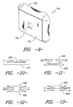
- FIG. 1 a fully deployed inflatable restraint cushion 10 in opposing relation to an occupant 12 located on the front seat 14 of a vehicle 16 such as an automobile, airplane or the like.
- the cushion 10 may be deployed outwardly from the dash panel 18 from a position directly opposed to the occupant 12. It is to be understood, however, that the cushion 10 may likewise be deployed from any other desired location in the vehicle 16 including the steering wheel (not shown), the vehicle side panels, the floor or the backrest of the front seat 14 for disposition in opposing relation to a rear passenger (not shown).
- the inflatable restraint cushion 10 preferably includes a body portion 22 and a base portion 24 which are joined together by stitching or other appropriate attachment practices as may be known to those of skill in the art.
- the base portion 24 preferably includes at least one inlet 26 for the acceptance of inflation media from an inflator. Both the base portion 24 and the body portion 22 may also include vents (not shown) for the release of the inflation media subsequent to inflation.
- the inflatable restraint cushion 10 is formed from fabric woven from nylon 6,6 available from E.I. DuPont deNemours in Wilmington, Delaware although other materials including, without limitation, other polyamides, polyesters, and polyacrylonitriles may also be utilized. Such fabrics may be either coated or non-coated as desired. While woven fabrics may be preferred, alternative materials of construction such as nonwovens or polymer films may likewise be utilized if desired. Moreover, it is contemplated that different materials may be used in different portions of the inflatable cushion 10 to achieve desired characteristics of air permeability and strength.
- FIGS. 3-8 The potentially preferred assembly practice for the inflatable restraint cushion 10 shown in FIGS. 1 and 2 is illustrated in FIGS. 3-8.
- this first section of material 30 is preferably of a generally quadrilateral and more specifically a square configuration although it is to be understood that alternative polygonal geometries having a plurality of perimeter edges such as triangles, pentagons, hexagons and octagons may also be utilized.
- the first section of material 30 is preferably folded along fold lines as indicated.
- a first flap section F1 of the first section of material 30 is folded along fold line A-A located in opposing relation to a first perimeter edge 31 of the first section of material 30. While the fold line A-A is illustrated as being in generally parallel orientation with respect to the first perimeter edge 31, it is to be understood that the desired opposing relation between these elements may also be achieved by non-parallel orientations.
- the first flap section F1 is folded back upon itself along fold line B-B which is located intermediate fold line A-A and the first perimeter edge 31. This fold along fold line B-B is preferably in reverse direction to the fold along fold line A-A. As best seen in FIG.
- this folding operation gives rise to a "Z" profile folded lap or sandwich structure between the interior of the first section of material 30 and the first perimeter edge 31.
- This folded lap structure preferably includes a layered structure of three interior layers and an attachment margin outboard of the interior layers for attachment of a second section of material as described further below. It is to be appreciated that the term "Z" profile lap structure as used herein is intended to cover any fold structure having reverse directed laps without limitation to any specific relative orientation of such laps.
- the final disposition of the first perimeter edge 31 subsequent to the above folding operation is preferably outboard of the overlapping interior layers to provide the attachment margin 33.
- This outboard disposition is preferably achieved by making the distance between the first perimeter edge 31 and the fold line B-B slightly greater than the distance between fold line A-A and fold line B-B.
- a second "Z" profile lap structure including an outboard attachment margin is formed by folding a second flap section F2 over along a fold line D-D located in opposing relation to a second perimeter edge 32 of the first section of material 30 and introducing a fold in reverse direction along a fold line E-E intermediate fold line D-D and the second perimeter edge 32.
- a "Z" profile lap structure is preferably formed wherein fold lines B-B and E-E are lapped over fold lines A-A and D-D respectively to lie in an inboard orientation with respect thereto along the interior longitudinal disposition lines shown in FIG. 3. Accordingly, the first perimeter edge 31 and second perimeter edge 32 are shifted inwardly to preferably form outboard peripheral attachment margins 33 and 34 for use in the attachment of additional material structures.
- the initial folds in each flap section may first be made along lines B-B and E-E and thereafter in reverse direction along lines A-A and D-D respectively to achieve the same construction as shown in FIGS 4 and 5. Accordingly, it is to be understood that the terms “first fold”, “second fold”, etc. as used herein are not intended to define any specific required sequence of operations.
- FIG. 5A illustrates the profile of a first section of material folded according to the practice of extending the fold lines beyond the center of the material blank to form an overlapping structure. It is, of course, to be understood that a folded structure could also be formed wherein some folded flap structures extend beyond the center of the material blank while other folded flap structures do not.
- the folding operation may be terminated after the introduction of folds in one or two flap sections as illustrated and described above, in the potentially preferred practice the folding of the first section of material 30 is carried further by folding a third flap section F3 about fold line G-G located in opposing relation to a third perimeter edge 37 of the first section of material.
- the third flap section F3 is folded back upon itself along a fold line H-H located intermediate the third perimeter edge 37 and fold line G-G to create an overlapping "Z" profile lap structure similar to that described above.
- a fourth flap section F4 is thereafter folded inwardly about fold line I-I located in opposing relation to a fourth perimeter edge 38 of the first section of material 30.
- the fourth flap section F4 is folded back upon itself along a fold line J-J located intermediate the fourth perimeter edge 38 and fold line I-I to create an overlapping "Z" profile lap configuration.
- the folded structure resulting from the above-described folding steps is illustrated in overhead view in FIG. 6 and shown in elevated perspective in FIG. 7.
- the manipulation of the third flap section F3 and the fourth flap section F4 results in an inward shifting of fold lines H-H and J-J to positions inboard of fold lines G-G and I-I respectively along the interior lateral disposition lines shown in FIGS. 3 and 4.
- the folding of third flap section F3 and fourth flap section F4 over the previously folded first and second flap sections F1 and F2 results in portions of the first section of material being formed into triple overlapping lap structures having nine layers of material.
- an outer perimeter attachment margin is preferably formed around the entire perimeter of the first section of material as best illustrated in FIG. 6. It will be appreciated that this outer perimeter attachment margin may be of virtually any width although a width of at least 1 millimeter and more preferably at least 5 millimeters may be preferred to enhance the ease of attachment of the second section of material as described below. As will be understood, an attachment margin which is too narrow may lead to assembly difficulties since without a proper margin the overlapping interior layers may interfere with the attachment of a second material section as described below. Moreover, as will be described further below, making the attachment at some distance from the fold lines permits the attachment of a second section of material which is substantially larger than the folded portion of the first section thereby permitting an increase in the volume and control of the shape of the expanded cushion.
- a second section of material 40 corresponding to the base section 24 of the inflatable restraint cushion 10 illustrated in FIG. 2 is placed in opposing mating relation to the folded first section of material 30 and adjoined thereto within the attachment margins outboard of the overlapping interior layers. It is to be understood that while the second section of material 40 has been shown as overlying the first section of material 30 during the assembly practice, the second section of material 40 could likewise be placed in an underlying position prior to the attachment of the two sections.
- the second section of material 40 may be composed at least in part of the same material as the first section of material 30 or may be of an entirely different composition to provide different response characteristics in the event of a collision.
- the first section of material 30 may be formed from a low permeability fabric for use in contacting the vehicle occupant 12, while the second section of material 40 may be formed from a higher permeability material to facilitate venting of the inflation media.
- the second section of material 40 includes an inlet opening 26 for introduction of inflation media as is well known to those of skill in the art. It is to be appreciated, however, that such an inlet opening could likewise be disposed in the first section of material if desired. Moreover it will be appreciated that whichever section of material includes an inlet opening 26 may also include neck extensions and/or reinforcements (not shown) as may be useful in facilitating attachment to inflation devices, although the highly expansible nature of the folded cushion does not rely on such neck extensions to provide expanded depth of coverage. Moreover, it is to be understood that any cushion formed according to the present invention may also include tethers as are well known to those of skill in the art to provide additional control over expansion during deployment.
- the second section of material 40 is shown as being completely separate from the first section of material 30. It is to be understood, however, that the second section of material may well form a part of the first section of material which is folded over into place in opposing relation to the folded first section of material following the introduction of one or more expansible lap structures as described above.
- folds may be introduced into the first, second and third flap sections F1, F2, F3 as described above, after which the fourth flap section F4 may be folded inwardly to cover the previously folded areas thereby forming an enclosure with three expansible sides.
- the attachment of the second section of material 40 to the first section of material 30 is illustrated in plan view in FIG. 8.
- four substantially straight seam lines 50, 51, 52 and 53 are used to join the second section of material to the outboard attachment margins at the perimeter edges of the folded first section of material 30, although non-straight seams could, of course, be utilized if desired.
- the introduction of these seam lines may be carried out entirely by sewing on a flat surface using equipment as is well known to those of skill in the art, thereby enhancing the ease of production. It is to be understood that while flat sewing may be the preferred method of attachment between the first and second sections of material, alternative methods of attachment such as adhesives, heat sealing and the like may likewise be utilized.
- first and second sections of material 30, 40 which are substantially square in configuration
- the practice of the present invention is readily adaptable to a variety of geometries.
- the first and second sections of material may be of an elongated rectangular configuration giving rise to an elongated cushion 110 as illustrated in FIG. 9.
- this elongated configuration may be assembled in precisely the same manner as illustrated and described above in relation to a square configuration and may be adaptable for use in environments where coverage of a broad surface area is desired.
- the cushion of the present invention may be turned inside out following attachment of the first and second sections of material if desired so as to remove the seams from the outer surface.
- first section of material is identified by reference numerals 230, 330, 430, 530, 630, 730, 830 and 930 and the second section of material is identified by reference numerals 240, 340, 440, 540, 640, 740, 840 and 940 respectively.
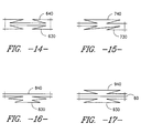
- first and second sections of material in any of the assembly relationships may be provided with an intermediate barrier element member 60 as shown in FIG. 17.
- an intermediate barrier element may be used to at least partially segregate portions of the resulting enclosure thereby defining at least two different compartments.
- the intermediate barrier element 60 has been illustrated in conjunction with the assembly relationship as illustrated in FIG. 12, the use of such a barrier element is likewise amenable to use in any other assembly relationship including those illustrated in FIGS. 7, 10, 11, 13, 14, 15 and 16.
- a double "Z" profile lap structure as shown in FIG. 16 may be used on any embodiment to effect further expansion if desired.
- the present invention is adaptable to produce cushion geometries having greater complexity than the substantially symmetrical square and rectangular box configurations as shown in FIGS. 2 and 9.
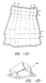
- One such alternative is illustrated in FIGS. 18, 19 and 20 wherein the first fabric section 1030 includes fold lines oriented with respect to one another to produce broad attachment margins outboard of the overlapping interior folds.
- a second section of material may be joined to these broad attachment margins in substantially the same manner as illustrated and described in relation to FIGS 7 and 8 although the distance between the outer most fold line and the seam line will be substantially greater.
- Joining the second section of material to the outer portion of a broad attachment margin permits the cushion to have an expanded configuration with a broad base and a body which extends to a more narrow top, thereby yielding a final expanded shape generally in the form of a truncated pyramid.
- a "Z" profile lap structure is introduced by making a longitudinal fold along line L-L and introducing a fold in the opposite direction along line M-M in the manner previously described.
- a longitudinal "Z" profile lap structure is introduced by placing a fold along line N-N and making a reverse fold along line O-O.
- Lateral folds are introduced by making a fold along line P-P and a reverse fold along line Q-Q as well as a fold along line R-R and a reverse fold along line S-S.
- the distance between the first perimeter edge 1031 and fold line M-M is substantially larger than the distance between fold line M-M and fold line L-L thereby yielding a wide outboard attachment margin equal to the difference.
- the distance between the second perimeter edge 1032 and fold line O-O is substantially larger than the distance between fold line O-O and N-N thereby yielding another broad attachment margin.
- the distance between the third perimeter edge 1037 and fold line Q-Q is greater than the distance between fold line Q-Q and P-P.
- the distance between the fourth perimeter edge 1038 and fold line S-S is greater than that between fold line S-S and R-R.
- the attachment of a second section of material to the folded structure may be carried out in the same manner as illustrated and described in relation to the box-like configurations above except that the seam line is substantially outboard of the outermost fold line.
- four seams 1050, 1051, 1052 and 1053 can be used to connect the first and second sections of material (FIG. 19).
- each of the attachment margins is substantially equivalent to the other attachment margins and the seam lines are located at a standard distance from each of the outboard perimeter edges.
- the expanded cushion which results from this folding and attachment practice is shown in FIG. 20.
- a large second section of material may be adjoined around the attachment margin thereby yielding a broad base portion 1024.
- a body portion 1022 which corresponds to the folded first fabric section 1030 extends in a substantially symmetrical truncated pyramidal configuration extending from the broad base 1024 to a smaller top. It is to be understood that the substantially symmetrical configuration of the cushion illustrated in FIG. 20 is due to the symmetrical placement of each of the seam lines on the equivalent outboard attachment margins.
- nonsymmetrical configurations may be achieved by altering the placement of the seam lines on the attachment margins or by incorporating attachment margins of different widths around the perimeter of the folded fabric section.
- broad outboard attachment margins could be formed at perimeter edges 1031 and 1032 with narrow attachment margins being formed at perimeter edges 1037 and 1038.
- the attachment of a second section of material about the outer edges of such attachment margins will have the result of modifying the expanded symmetrical truncated pyramid configuration illustrated in FIG. 20 to a more elongated, wedge-shaped structure.
- the final inflated shape of the cushion 1010 will not have the straight sided configuration as illustrated for enablement purposes in FIG. 20, but will rather have a more rounded configuration due to the distribution of pressure throughout the enclosure. It is believed, however, that the general overall shape having a broad base and a more narrow top will nonetheless be maintained.
- the final geometry of the cushion of the present invention may be further altered and controlled by the introduction of angled folds in the lateral and/or longitudinal directions of the first section of material.
- the fold lines are substantially similar to those illustrated and described in relation to FIG. 18, although the longitudinal folds run in non-parallel relation to one another to yield substantially trapezoidal webs of material between the fold lines.
- the lateral fold lines are angled in opposite directions with respect to one another to yield differences in the slope of the cushion profile.
- the final cushion configuration 1110 which results from the use of a material section folded according to the pattern illustrated in FIG. 20 is a trapezohedron as illustrated in FIG.
- each side of the resultant cushion is a different sized trapezium thereby providing for a maximum differential in size and shape between each of the sides so as to generate an extremely complex overall geometry if desired.
- the introduction of non-parallel fold lines into one or more of the sections of material to form expansible segments of trapezoidal or triangular shape permits the final configuration of the inflatable restraint cushion to be greatly modified to meet individual design criteria since a broad portion of a folded structure will yield a deep expanded configuration resulting from a broad web of entrained material and a narrow portion of a folded structure will result in a correspondingly more shallow expanded structure.
- the method of the present invention may provide an extensive number of different geometries wherein the expanded cushion has shallow and deep portions formed by different fold structures. Accordingly, while several potential embodiments have been illustrated and described, any number of other embodiments may likewise be utilized.
- a primary benefit of the present invention is the ability to form a three-dimensional expansible cushion by two-dimensional folding and adjoining practices.
- These folding and adjoining practices may be carried out by hand or may be effected by mechanized technologies.
- mechanized folding operations may be carried out by equipment utilizing sliding plate folding technologies as are well known to those of skill in the art.
- the adjoining practices may be carried out utilizing standard industrial sewing equipment as is well known to those of skill in the art.
- the present invention provides an inflatable restraint cushion and method of assembly therefore wherein the cushion may be formed entirely by flat folding and adjoining operations. While the present invention has been illustrated and described in accordance with certain preferred embodiments it is to be appreciated that such are not to be construed as unduly limiting the invention since modifications may be made and other embodiments of the principles of this invention will occur to those of skill in the art to which this invention pertains. It is therefore contemplated by the appended claims to cover any such modifications and equivalent embodiments as incorporate the features of this invention within the scope of the following claims.
Landscapes
- Engineering & Computer Science (AREA)
- Mechanical Engineering (AREA)
- Vehicle Interior And Exterior Ornaments, Soundproofing, And Insulation (AREA)
- Air Bags (AREA)
Claims (28)
- Un coussin de retenue pour passager (10; 1010) pour gonflage dans un véhicule (16) transportant au moins une personne (12), le coussin de retenue pour passager comprenant:une première section de tissu (30; 1030) ayant un centre et un périmètre comprenant une pluralité de bords de périmètre (31; 32; 37; 38; 1031; 1032; 1037; 1038) et un premier pli formé le long d'une première ligne de pli (A-A; L-L);une seconde section de tissu (40) placée à l'opposé et contre la première section de tissu (30; 1030); etun moyen pour attacher la première section de tissu (30; 1030) à la seconde section de tissu (40);
caractérisé en ce que la première section de tissu (30; 1030) comprend au moins une structure de nappe en profil "Z" comprenant ledit premier pli formé le long de ladite première ligne de pli (A-A; L-L) disposé à l'opposé d'un premier bord de périmètre (31; 1031), et un second pli dans le sens inverse au premier pli disposé le long d'une seconde ligne de pli (B-B; M-M) située entre la première ligne de pli et le premier bord de périmètre de sorte qu'une partie du tissu (30; 1030) entre le centre et le premier bord de périmètre (31; 1031) de la première section de tissu comprenne une structure en couches comprenant une pluralité de couches internes chevauchantes et une marge de fixation disposée à l'extérieur des couches internes chevauchantes; et en ce que ladite première section de tissu (30; 1030) est attachée à ladite seconde section de tissu (40) autour du périmètre de la première section de tissu à l'intérieur de la marge de fixation pour former un espace fermé entre les première et seconde sections de tissu. - Un coussin selon la revendication 1, dans lequel la première section de tissu (30; 1030) comprend au moins deux structures de nappe en profil "Z" chacune comprenant des couches internes chevauchantes et des marges de fixation disposées à l'extérieur des couches chevauchantes.
- Un coussin selon la revendication 2, dans lequel au moins deux structures de nappe en profil "Z" s'entrecoupent.
- Un coussin selon la revendication 2, dans lequel deux structures de nappe en profil "Z" ne s'entrecoupent pas.
- Un coussin selon l'une quelconque des revendications précédentes, dans lequel la seconde section (40) de tissu comprend au moins une structure de nappe en profil "Z" qui y est disposée.
- Un coussin selon l'une quelconque des revendications précédentes, dans lequel la première section de tissu (30; 1030) est d'une perméabilité à l'air différente de la seconde section de tissu (40).
- Un coussin selon l'une quelconque des revendications précédentes, dans lequel soit la première section de tissu (30; 1030) soit la seconde section de tissu (40) comprend une étoffe enduite.
- Un coussin selon l'une quelconque des revendications précédentes, dans lequel le moyen pour attacher la première section de tissu (30; 1030) à la seconde section de tissu (40) comprend une pluralité de coutures piquées (50; 51; 52; 53; 1050; 1051; 1052; 1053).
- Un coussin selon la revendication 8, dans lequel la pluralité de coutures consiste en des coutures droites formées par des opérations de couture plate.
- Un coussin selon l'une quelconque des revendications 1 à 7, dans lequel la pluralité de coutures est formée par des moyens adhésifs.
- Un coussin selon l'une quelconque des revendications précédentes, dans lequel la première section de tissu (30; 1030) est de géométrie quadrilatère ayant un centre et un périmètre comprenant quatre bords de périmètre (31; 32; 37; 38; 1031; 1032; 1037; 1038) la première section de tissu (30; 1030) comprenant des structures de nappe en profil "Z" adjacentes à chacun des quatre bords de périmètre.
- Un coussin selon l'une quelconque des revendications précédentes, dans lequel la seconde section de tissu (40) est de géométrie quadrilatère.
- Un procédé pour fabriquer un coussin de retenue pour passager (10) à utiliser en conjonction avec un équipement de gonflage dans un véhicule (16) transportant au moins une personne (12), le procédé comprenant les étapes de:l'exécution d'un premier pli dans une première section de tissu (30; 1030) ayant un centre et une pluralité de bords de périmètre (31; 32; 37; 38; 1031; 1032; 1037; 1038) le long d'une ligne de pli (A-A; L-L) disposée à l'opposé d'un premier bord de périmètre (31; 1037) de la première section de tissu;
le procédé étant caractérisé parl'exécution d'au moins un second pli dans la première section de tissu (30; 1030) le long d'une ligne de pli disposée entre la ligne de pli (A-A; L-L) pour le premier pli et le premier bord de périmètre (31; 1031) de la première section de tissu (30; 1030) dans le sens inverse au premier pli, de manière à ce qu'au moins une partie du tissu disposé entre le premier bord de périmètre (31; 1031) de la première section de tissu et le centre de la première section de tissu soit formée en une structure de nappe en profil "Z" comprenant une multiplicité de couches internes chevauchantes et une marge de fixation à l'extérieur des couches internes chevauchantes;la mise en contact d'une seconde section de tissu (40) avec la première section de tissu (30; 1030); etla mise côte à côte de la seconde section de tissu (40) et de la première section de tissu (30; 1030) pliée selon les étapes ci-dessus à l'intérieur de la marge de fixation à l'extérieur des couches internes chevauchantes. - Un procédé selon la revendication 13, dans lequel la seconde section de tissu (40) est mise côte à côte avec la première section de tissu (30; 1030) en cousant l'intérieur du périmètre entier de la première section de tissu.
- Un procédé selon la revendication 13 ou la revendication 14, dans lequel la seconde section de tissu (40) comprend au moins une structure de nappe pliée le long de son bord de périmètre.
- Un procédé selon l'une quelconque des revendications 13 à 15, comprenant les étapes intermédiaires supplémentaires avant l'étape de la mise côte à côte consistant à:faire un troisième pli dans la première section de tissu le long d'une ligne de pli (D-D; N-N) disposée à l'opposé d'un second bord de périmètre (32; 1032) de la première section de tissu (30; 1030); etfaire au moins un quatrième pli dans la première section de tissu (30; 1030) le long d'une ligne de pli disposée entre la ligne de pli (D-D; N-N) pour le troisième pli et le second bord de périmètre (32; 1032) de la première section de tissu dans le sens inverse au troisième pli, de manière à ce qu'au moins une partie du tissu disposé entre le second bord de périmètre (32; 1032) et le centre de la première section de tissu soit formée en une structure de nappe en profil "Z" comprenant une multiplicité de couches internes chevauchantes et une marge de fixation à l'extérieur des couches internes chevauchantes.
- Un procédé selon la revendication 16, dans lequel le premier bord de périmètre (31; 1031) et le second bord de périmètre (32; 1032) s'entrecoupent.
- Un procédé selon la revendication 16, dans lequel le premier bord de périmètre (31; 1031) et le second bord de périmètre (32; 1032) ne s'entrecoupent pas.
- Un procédé selon l'une quelconque des revendications 16 à 18, comprenant les étapes intermédiaires supplémentaires avant l'étape de la mise côte à côte consistant à:faire un cinquième pli dans la première section de tissu (30; 1030) le long d'une ligne de pli (G-G; P-P) disposée à l'opposé d'un troisième bord de périmètre (37; 1037) de la première section de tissu; etfaire au moins un sixième pli dans la première section de tissu (30; 1030) le long d'une ligne de pli (H-H; Q-Q) disposée entre la ligne de pli du cinquième pli et le troisième bord de périmètre (37; 1037) de la première section de tissu dans le sens inverse au cinquième pli, de manière à ce qu'au moins une partie du tissu disposé entre le troisième bord de périmètre (37; 1037) et le centre de la première section de tissu soit formée en une structure de nappe en profil "Z" comprenant une multiplicité de couches internes chevauchantes et une marge de fixation à l'extérieur des couches internes chevauchantes.
- Un procédé selon la revendication 19, comprenant les étapes intermédiaires supplémentaires, avant l'étape de la mise côte à côte, consistant à:faire un septième pli dans la première section de tissu (30; 1030) le long d'une ligne de pli (I-I; R-R) disposée à l'opposé d'un quatrième bord de périmètre (38; 1038) de la première section de tissu; etfaire au moins un huitième pli dans la première section de tissu (30; 1030) le long d'une ligne de pli (J-J; S-S) disposée entre la ligne de pli pour le septième pli (I-I; R-R) et le quatrième bord de périmètre (38; 1038) de la première section de tissu dans le sens inverse au septième pli, de manière à ce qu'au moins une partie du tissu disposé entre le quatrième bord de périmètre et le centre de la première section de tissu soit formée en une structure de nappe en profil "Z" comprenant une multiplicité de couches chevauchantes et une marge de fixation à l'extérieur des couches chevauchantes.
- Un procédé selon la revendication 20, dans lequel la première pièce d'étoffe est formée en première, seconde, troisième et quatrième structures de nappe en profil "Z" ayant chacune au moins trois couches internes chevauchantes et une marge de fixation à l'extérieur des couches internes chevauchantes.
- Un procédé selon l'une quelconque des revendications 13 à 21, dans lequel la première section de tissu (30; 1030) est de géométrie quadrilatère.
- Un procédé selon l'une quelconque des revendications 13 à 22, dans lequel la seconde section de tissu (40) est mise côte à côte avec la première section de tissu (30; 1030) en cousant à l'intérieur de tout la périmètre de la première section de tissu aussi bien qu'à l'intérieur de la marge de fixation formée par les structures de nappe en profil "Z".
- Un procédé selon l'une quelconque des revendications 13 à 23, dans lequel les plis sont faits dans la première section de tissu dans un ordre séquentiel.
- Un procédé salon l'une quelconque des revendications 13 à 24, dans lequel le premier pli, la second pli et la premier bord de périmètre ne sont pas parallèles las uns aux autres.
- Un procédé salon l'une quelconque des revendications 16 à 25, dans lequel le troisième pli, le quatrième pli et la second bord de périmètre ne sont pas parallèles les uns aux autres.
- Un procédé selon l'une quelconque des revendications 19 à 26, dans lequel le cinquième pli, le sixième pli et le troisième bord de périmètre ne sont pas parallèles les uns aux autres.
- Un procédé selon l'une quelconque des revendications 20 à 27, dans lequel le septième pli, le huitième pli et le quatrième bord de périmètre ne sont pas parallèles les uns aux autres.
Applications Claiming Priority (2)
| Application Number | Priority Date | Filing Date | Title |
|---|---|---|---|
| US08/277,618 US5445414A (en) | 1994-07-20 | 1994-07-20 | Inflatable occupant restraint cushion |
| US277618 | 1994-07-20 |
Publications (3)
| Publication Number | Publication Date |
|---|---|
| EP0693403A2 EP0693403A2 (fr) | 1996-01-24 |
| EP0693403A3 EP0693403A3 (fr) | 1996-07-31 |
| EP0693403B1 true EP0693403B1 (fr) | 1999-01-20 |
Family
ID=23061654
Family Applications (1)
| Application Number | Title | Priority Date | Filing Date |
|---|---|---|---|
| EP95303886A Expired - Lifetime EP0693403B1 (fr) | 1994-07-20 | 1995-06-06 | Coussin gonflable de retenue pour passager |
Country Status (3)
| Country | Link |
|---|---|
| US (1) | US5445414A (fr) |
| EP (1) | EP0693403B1 (fr) |
| DE (1) | DE69507391D1 (fr) |
Families Citing this family (14)
| Publication number | Priority date | Publication date | Assignee | Title |
|---|---|---|---|---|
| US5529339A (en) * | 1995-03-20 | 1996-06-25 | General Motors Corporation | Air bag fold and method |
| US5529340A (en) * | 1995-08-14 | 1996-06-25 | Morton International, Inc. | Single piece pattern air bag |
| US5697640A (en) * | 1996-02-16 | 1997-12-16 | Trw Vehicle Safety Systems Inc. | Pleated air bag |
| US5839756A (en) * | 1997-02-03 | 1998-11-24 | General Motors Corporation | Inflatable bladder |
| US5803483A (en) * | 1997-03-20 | 1998-09-08 | Autoliv Asp, Inc. | Airbag cushion and method of folding thereof |
| US6220309B1 (en) | 1999-09-24 | 2001-04-24 | Milliken & Company | Inflatable fabrics comprising basket-woven attachment points between fabric panels |
| WO2004011308A1 (fr) * | 2002-07-25 | 2004-02-05 | Autoliv Development Ab | Coussin gonflant pour dispositif de retenue d'occupant et procede de fabrication de coussin gonflant |
| US6848715B2 (en) * | 2002-08-26 | 2005-02-01 | Autoliv Asp, Inc. | Folded rigid knee airbag |
| JP4446831B2 (ja) * | 2004-08-05 | 2010-04-07 | 日本プラスト株式会社 | エアバッグ |
| US20060237957A1 (en) * | 2005-04-22 | 2006-10-26 | Takata Restraint Systems, Inc. | Sealed cushion |
| US20110260436A1 (en) | 2010-04-27 | 2011-10-27 | Park Hae Kwon | Passenger airbag apparatus |
| JP5433494B2 (ja) * | 2010-04-28 | 2014-03-05 | 芦森工業株式会社 | 助手席用エアバッグ装置のクッションの製造方法 |
| US8764055B2 (en) * | 2011-09-02 | 2014-07-01 | Trw Vehicle Safety Systems Inc. | Air bag with pleated portion |
| KR20130095025A (ko) * | 2012-02-17 | 2013-08-27 | 현대모비스 주식회사 | 조수석 에어백 쿠션 |
Family Cites Families (19)
| Publication number | Priority date | Publication date | Assignee | Title |
|---|---|---|---|---|
| US2234065A (en) * | 1936-04-15 | 1941-03-04 | Owens Illinois Glass Co | Collapsible container |
| US2701878A (en) * | 1952-12-24 | 1955-02-15 | William M Davis | Sanitary finger cover |
| US3072270A (en) * | 1959-02-20 | 1963-01-08 | Thomas F Tolby | Disposable cargo cushion |
| FR1307286A (fr) * | 1961-08-19 | 1962-10-26 | Boîte d'emballage | |
| US3276670A (en) * | 1964-07-27 | 1966-10-04 | Kathryn B Harvey | Disposable plastic bag |
| US3358903A (en) * | 1966-03-31 | 1967-12-19 | West Virginia Pulp & Paper Co | Paper bags having leak-proof seams |
| US3618978A (en) * | 1970-05-11 | 1971-11-09 | Gen Motors Corp | Inflatable restraint for vehicle occupant |
| US3810654A (en) * | 1972-05-05 | 1974-05-14 | Gen Motors Corp | Occupant restraint cushion assembly and method of manufacture |
| US4235453A (en) * | 1974-05-13 | 1980-11-25 | Allied Chemical Corporation | Specially folded vehicle safety bag |
| JPS5123916A (en) * | 1974-08-19 | 1976-02-26 | Kohkoku Chem Ind | Eaabatsuguno oritatamihoho |
| US4010055A (en) * | 1975-06-06 | 1977-03-01 | Nissan Motor Co., Ltd. | Method of producing three-dimensionally shaped inflatable safety bag |
| US4491217A (en) * | 1982-02-16 | 1985-01-01 | Highland Supply Corp. | Corsage bag, blank and method of forming same |
| DE3544248C1 (de) * | 1985-12-14 | 1987-01-29 | Audi Ag | Aufblasbares Aufprallschutzkissen |
| JPH03186448A (ja) * | 1989-12-15 | 1991-08-14 | Takata Kk | パッセンジャー用エアバッグ |
| US5087071A (en) * | 1990-08-01 | 1992-02-11 | Trw Vehicle Safety Systems Inc. | Vehicle air bag structure and method of forming |
| JP3067795B2 (ja) * | 1990-11-27 | 2000-07-24 | マツダ株式会社 | 自動車用エアバッグ装置および自動車用エアバッグ折畳方法 |
| US5284358A (en) | 1992-05-15 | 1994-02-08 | Trw Vehicle Safety Systems Inc. | Air bag assembly |
| US5277230A (en) * | 1993-02-22 | 1994-01-11 | Milliken Research Corporation | Double twillwoven air bag fabric |
| US5348341A (en) * | 1993-11-01 | 1994-09-20 | General Motors Corporation | Method of folding an air bag |
-
1994
- 1994-07-20 US US08/277,618 patent/US5445414A/en not_active Expired - Lifetime
-
1995
- 1995-06-06 DE DE69507391T patent/DE69507391D1/de not_active Expired - Lifetime
- 1995-06-06 EP EP95303886A patent/EP0693403B1/fr not_active Expired - Lifetime
Also Published As
| Publication number | Publication date |
|---|---|
| EP0693403A2 (fr) | 1996-01-24 |
| EP0693403A3 (fr) | 1996-07-31 |
| US5445414A (en) | 1995-08-29 |
| DE69507391D1 (de) | 1999-03-04 |
Similar Documents
| Publication | Publication Date | Title |
|---|---|---|
| US5482318A (en) | Pleated inflatable cushion for passenger restraint | |
| US4944529A (en) | Inflatable protective cushion | |
| US5931498A (en) | Simplified air bag configuration | |
| US6494484B2 (en) | Polygon-shaped air bag | |
| EP0693403B1 (fr) | Coussin gonflable de retenue pour passager | |
| EP1147948B1 (fr) | Coussin gonflable de retenue | |
| US5839756A (en) | Inflatable bladder | |
| US6299205B1 (en) | Vehicle restraint system comprising an airbag having a looped pocket for inflation canister disposition | |
| US6837517B2 (en) | Multiple panel airbag and method | |
| US5855393A (en) | Simplified airbag configuration | |
| US20020060449A1 (en) | Multiple panel airbag and method | |
| JPH0710654B2 (ja) | 自動車用エアバッグのガイドシュート | |
| US6695346B1 (en) | Polygon-shaped air bag with lapping seam area | |
| US5697640A (en) | Pleated air bag | |
| US5794974A (en) | Inflatable restraint cushion | |
| US6666477B1 (en) | Inflatable restraint system and method | |
| US6180204B1 (en) | One piece air bag | |
| US6685215B2 (en) | Twelve-sided polygon-shaped air bag | |
| US6547709B1 (en) | Method of folding an air bag | |
| JPH07125592A (ja) | エアバッグ | |
| JPH0872656A (ja) | 助手席用エアバッグ装置 | |
| JPH0450200Y2 (fr) | ||
| JP2004513001A (ja) | 三次元の搭乗者用エアバッグ、及び該方法 | |
| WO1997036770A1 (fr) | Coussin gonflable de retenue | |
| JPH0948303A (ja) | エアバッグ及びエアバッグ折畳体 |
Legal Events
| Date | Code | Title | Description |
|---|---|---|---|
| PUAI | Public reference made under article 153(3) epc to a published international application that has entered the european phase |
Free format text: ORIGINAL CODE: 0009012 |
|
| AK | Designated contracting states |
Kind code of ref document: A2 Designated state(s): BE DE ES GB IT NL |
|
| PUAL | Search report despatched |
Free format text: ORIGINAL CODE: 0009013 |
|
| AK | Designated contracting states |
Kind code of ref document: A3 Designated state(s): BE DE ES GB IT NL |
|
| 17P | Request for examination filed |
Effective date: 19960813 |
|
| GRAG | Despatch of communication of intention to grant |
Free format text: ORIGINAL CODE: EPIDOS AGRA |
|
| 17Q | First examination report despatched |
Effective date: 19980520 |
|
| GRAG | Despatch of communication of intention to grant |
Free format text: ORIGINAL CODE: EPIDOS AGRA |
|
| GRAH | Despatch of communication of intention to grant a patent |
Free format text: ORIGINAL CODE: EPIDOS IGRA |
|
| GRAH | Despatch of communication of intention to grant a patent |
Free format text: ORIGINAL CODE: EPIDOS IGRA |
|
| GRAA | (expected) grant |
Free format text: ORIGINAL CODE: 0009210 |
|
| AK | Designated contracting states |
Kind code of ref document: B1 Designated state(s): BE DE ES GB IT NL |
|
| PG25 | Lapsed in a contracting state [announced via postgrant information from national office to epo] |
Ref country code: NL Free format text: LAPSE BECAUSE OF FAILURE TO SUBMIT A TRANSLATION OF THE DESCRIPTION OR TO PAY THE FEE WITHIN THE PRESCRIBED TIME-LIMIT Effective date: 19990120 Ref country code: IT Free format text: LAPSE BECAUSE OF FAILURE TO SUBMIT A TRANSLATION OF THE DESCRIPTION OR TO PAY THE FEE WITHIN THE PRESCRIBED TIME-LIMIT;WARNING: LAPSES OF ITALIAN PATENTS WITH EFFECTIVE DATE BEFORE 2007 MAY HAVE OCCURRED AT ANY TIME BEFORE 2007. THE CORRECT EFFECTIVE DATE MAY BE DIFFERENT FROM THE ONE RECORDED. Effective date: 19990120 Ref country code: ES Free format text: THE PATENT HAS BEEN ANNULLED BY A DECISION OF A NATIONAL AUTHORITY Effective date: 19990120 Ref country code: BE Free format text: LAPSE BECAUSE OF FAILURE TO SUBMIT A TRANSLATION OF THE DESCRIPTION OR TO PAY THE FEE WITHIN THE PRESCRIBED TIME-LIMIT Effective date: 19990120 |
|
| REF | Corresponds to: |
Ref document number: 69507391 Country of ref document: DE Date of ref document: 19990304 |
|
| PGFP | Annual fee paid to national office [announced via postgrant information from national office to epo] |
Ref country code: NL Payment date: 19990324 Year of fee payment: 5 |
|
| PGFP | Annual fee paid to national office [announced via postgrant information from national office to epo] |
Ref country code: BE Payment date: 19990329 Year of fee payment: 5 |
|
| PG25 | Lapsed in a contracting state [announced via postgrant information from national office to epo] |
Ref country code: DE Free format text: LAPSE BECAUSE OF FAILURE TO SUBMIT A TRANSLATION OF THE DESCRIPTION OR TO PAY THE FEE WITHIN THE PRESCRIBED TIME-LIMIT Effective date: 19990421 |
|
| NLV1 | Nl: lapsed or annulled due to failure to fulfill the requirements of art. 29p and 29m of the patents act | ||
| PLBE | No opposition filed within time limit |
Free format text: ORIGINAL CODE: 0009261 |
|
| STAA | Information on the status of an ep patent application or granted ep patent |
Free format text: STATUS: NO OPPOSITION FILED WITHIN TIME LIMIT |
|
| 26N | No opposition filed | ||
| REG | Reference to a national code |
Ref country code: GB Ref legal event code: IF02 |
|
| PGFP | Annual fee paid to national office [announced via postgrant information from national office to epo] |
Ref country code: GB Payment date: 20020527 Year of fee payment: 8 |
|
| PG25 | Lapsed in a contracting state [announced via postgrant information from national office to epo] |
Ref country code: GB Free format text: LAPSE BECAUSE OF NON-PAYMENT OF DUE FEES Effective date: 20030606 |
|
| GBPC | Gb: european patent ceased through non-payment of renewal fee |
Effective date: 20030606 |