EP0693448A2 - Dispositif automatique de transfert d'un ruban de corde - Google Patents
Dispositif automatique de transfert d'un ruban de corde Download PDFInfo
- Publication number
- EP0693448A2 EP0693448A2 EP95108825A EP95108825A EP0693448A2 EP 0693448 A2 EP0693448 A2 EP 0693448A2 EP 95108825 A EP95108825 A EP 95108825A EP 95108825 A EP95108825 A EP 95108825A EP 0693448 A2 EP0693448 A2 EP 0693448A2
- Authority
- EP
- European Patent Office
- Prior art keywords
- conveyor belt
- belt
- station
- transfer
- feed station
- Prior art date
- Legal status (The legal status is an assumption and is not a legal conclusion. Google has not performed a legal analysis and makes no representation as to the accuracy of the status listed.)
- Withdrawn
Links
- 229910000831 Steel Inorganic materials 0.000 description 1
- 238000006073 displacement reaction Methods 0.000 description 1
- 238000000034 method Methods 0.000 description 1
- 239000010959 steel Substances 0.000 description 1
- 239000004753 textile Substances 0.000 description 1
Images

Classifications
-
- B—PERFORMING OPERATIONS; TRANSPORTING
- B29—WORKING OF PLASTICS; WORKING OF SUBSTANCES IN A PLASTIC STATE IN GENERAL
- B29D—PRODUCING PARTICULAR ARTICLES FROM PLASTICS OR FROM SUBSTANCES IN A PLASTIC STATE
- B29D30/00—Producing pneumatic or solid tyres or parts thereof
- B29D30/06—Pneumatic tyres or parts thereof (e.g. produced by casting, moulding, compression moulding, injection moulding, centrifugal casting)
- B29D30/38—Textile inserts, e.g. cord or canvas layers, for tyres; Treatment of inserts prior to building the tyre
-
- B—PERFORMING OPERATIONS; TRANSPORTING
- B29—WORKING OF PLASTICS; WORKING OF SUBSTANCES IN A PLASTIC STATE IN GENERAL
- B29C—SHAPING OR JOINING OF PLASTICS; SHAPING OF MATERIAL IN A PLASTIC STATE, NOT OTHERWISE PROVIDED FOR; AFTER-TREATMENT OF THE SHAPED PRODUCTS, e.g. REPAIRING
- B29C31/00—Handling, e.g. feeding of the material to be shaped, storage of plastics material before moulding; Automation, i.e. automated handling lines in plastics processing plants, e.g. using manipulators or robots
-
- B—PERFORMING OPERATIONS; TRANSPORTING
- B29—WORKING OF PLASTICS; WORKING OF SUBSTANCES IN A PLASTIC STATE IN GENERAL
- B29D—PRODUCING PARTICULAR ARTICLES FROM PLASTICS OR FROM SUBSTANCES IN A PLASTIC STATE
- B29D30/00—Producing pneumatic or solid tyres or parts thereof
- B29D30/06—Pneumatic tyres or parts thereof (e.g. produced by casting, moulding, compression moulding, injection moulding, centrifugal casting)
- B29D30/38—Textile inserts, e.g. cord or canvas layers, for tyres; Treatment of inserts prior to building the tyre
- B29D30/44—Stretching or treating the layers before application on the drum
-
- B—PERFORMING OPERATIONS; TRANSPORTING
- B65—CONVEYING; PACKING; STORING; HANDLING THIN OR FILAMENTARY MATERIAL
- B65H—HANDLING THIN OR FILAMENTARY MATERIAL, e.g. SHEETS, WEBS, CABLES
- B65H20/00—Advancing webs
- B65H20/06—Advancing webs by friction band
-
- B—PERFORMING OPERATIONS; TRANSPORTING
- B65—CONVEYING; PACKING; STORING; HANDLING THIN OR FILAMENTARY MATERIAL
- B65H—HANDLING THIN OR FILAMENTARY MATERIAL, e.g. SHEETS, WEBS, CABLES
- B65H2801/00—Application field
- B65H2801/93—Tyres
Definitions
- the invention relates to a device for automatically transferring a belt, in particular a cord belt, from an unwinding station to a feed station comprising a conveyor belt.
- the cord strip In the course of processing cord strips into car tires, the cord strip must be cut into strips at least once in a cutting device, these strips, which are usually cut at an angle, then being spliced together again in a different assignment.
- a roll of cord tape is hung in an unwinding station and from there it is led to a feed station, usually comprising a conveyor belt, which is then followed by the cutting device and further processing devices.
- the transfer from the unwinding station to the feed station has hitherto been carried out manually, with two workers usually pulling the tape down from the output roller of the unwinding station in order to thread it into the feed station.
- the invention is therefore based on the object of providing a device for automatically transferring the tape from an unwinding station to a feed station, in which the tape no longer has to be touched by hand.
- such a device is characterized according to the invention by an inclined transfer conveyor belt which can be moved parallel to its conveying direction upwards from a non-use position inserted under the feed station and below the dispensing roller of the unwinding station carrying the belt and in this extended position with its lower end upwards is pivotable into a transfer position to the conveyor belt of the feed station.
- a detector for the tape associated with a shutdown device for driving the unwinder can be provided under the output roller of the unwinder.
- the drive of the unwinding station is switched off, so that the transfer conveyor belt, which continues to run, then the conveyor belt retracted in the wrong direction, thus eliminating the fault.
- the detector releases the drive for the unwinding station.
- the design of the device according to the invention is particularly advantageously such that when the lower end of the transfer conveyor belt is pivoted, a gear connection is made with the drive of the conveyor belt of the feed station, in particular in such a way that the lower deflection roller of the transfer conveyor belt carries at least one gear, meshing with a counter gear connected to the conveyor belt drive when the lower end is pivoted.
- any separate drive for the transfer conveyor belt is spared, which not only means saving a corresponding drive motor, but in particular also eliminates the issue of synchronicity between the transfer conveyor belt and the conveyor belt of the feed station.
- the displacement of the transfer conveyor belt can be accomplished very simply in such a way that the transfer conveyor belt itself, which is designed without a drive, is mounted in a sliding frame, which in turn is guided obliquely displaceably between two lateral columns, the sliding frame preferably having at least one with an output gear one in a column built-in drive motor has a meshing rack.
- Fig. 1, 1 is the only schematically shown unwinding station of a cord belt 3 suspended on a roll 2 in the unwinding station with an output roller 4, while 5 indicates the conveyor station, of which in the drawing only the beginning of the conveyor belt 6 with the front idler roller 7 is shown.
- the cord tape 3 unwound from the roll 2 must now be conveyed from the unwinding station 1 to the feed station 5, whereby in the operating position it is guided by a belt tensioning device 8 shown schematically in FIG. 1, which comprises tensioning rollers 10 and 11 in addition to lateral columns 9.
- the tensioning roller 11 can be lifted along the columns 9 upwards over the output roller 4 and the second tensioning roller 10 can be moved downward, so that the cord band in the space between the unwinding station 1 and the feed station 5 via the transfer station 12, which will be described in detail below 3 can be transferred fully automatically from the unwind station to the feed station. Then the tensioning rollers 10 and 11 are again moved into the working position indicated in FIG. 1, in which the cord band 3 forms a tensioning loop. Of course, this only takes place when the transfer device has moved back from the working position shown in FIG. 1 to the non-use position shown in FIG. 2.
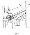
- the transfer device 12 comprises a conveyor belt 13 which is pivotally mounted in a sliding frame 14 about the axis 15 of the upper deflecting roller 16 in such a way that the lower deflecting roller 17 with the aid of hydraulic actuating members 18 shown schematically in Fig. 3 in the in Fig. 1st and 3 shown transfer position to the conveyor belt 6 of the feed station can be raised.
- the transfer device comprises two lateral guide columns 27, in which the guide frame 14 is guided so that it can be moved obliquely, so that it can be moved out of the non-use position shown in FIG. 2 - the guides themselves are not shown for the sake of clarity - upwards parallel to themselves into the position Fig. 1 or 3 can be brought, but first the conveyor belt 13 is still folded parallel to the frame 14 below.
- Two gearwheels 19 arranged on the two outer sides of the deflection roller 17 preferably come into meshing engagement with a gearwheel 20 which is in geared connection with a gearwheel 21 of the deflection roller 7 of the conveyor belt 6 of the feed station 5.
- the drive of the transfer conveyor belt 13 is thus derived directly from the drive of the conveyor belt of the feed station, so that the necessary synchronism is also guaranteed.
- the transfer conveyor belt 13 with its sliding frame 14 is extended with the aid of an electric motor 22 which drives a gearwheel 23 which in turn meshes with a toothed rack 24 on the sliding frame 14.
- an electric motor 22 which drives a gearwheel 23 which in turn meshes with a toothed rack 24 on the sliding frame 14.
- racks and gears are on both sides provided, the two gears 23 being connected to one another by a shaft, so that only one electric motor 22 is required.
- a detector 25 can be seen schematically under the output roller 4 in FIG. 1, which detects whether, contrary to the position shown in FIG. 1, the tape is not accidentally drawn in to the right under the roller.
- the drive motor for the unwinding station 1 is switched off via the detector and a downstream switch-off device, so that if the drive for the transfer conveyor belt 13 continues to run, it pulls out the wrongly pulled-in belt 3 and conveys it to the feed station in the conveying direction 26 shown.
Landscapes
- Engineering & Computer Science (AREA)
- Mechanical Engineering (AREA)
- Textile Engineering (AREA)
- Robotics (AREA)
- Tyre Moulding (AREA)
- Structure Of Belt Conveyors (AREA)
Applications Claiming Priority (2)
| Application Number | Priority Date | Filing Date | Title |
|---|---|---|---|
| DE19944425417 DE4425417C1 (de) | 1994-07-19 | 1994-07-19 | Automatische Bandübergabevorrichtung |
| DE4425417 | 1994-07-19 |
Publications (2)
| Publication Number | Publication Date |
|---|---|
| EP0693448A2 true EP0693448A2 (fr) | 1996-01-24 |
| EP0693448A3 EP0693448A3 (fr) | 1997-10-15 |
Family
ID=6523509
Family Applications (1)
| Application Number | Title | Priority Date | Filing Date |
|---|---|---|---|
| EP95108825A Withdrawn EP0693448A3 (fr) | 1994-07-19 | 1995-06-08 | Dispositif automatique de transfert d'un ruban de corde |
Country Status (2)
| Country | Link |
|---|---|
| EP (1) | EP0693448A3 (fr) |
| DE (1) | DE4425417C1 (fr) |
Cited By (2)
| Publication number | Priority date | Publication date | Assignee | Title |
|---|---|---|---|---|
| FR3062338A1 (fr) * | 2017-01-31 | 2018-08-03 | Compagnie Generale Des Etablissements Michelin | Planeite de nappes de caoutchouc renforce au cours de la production de pneumatiques |
| CN112693059A (zh) * | 2020-12-28 | 2021-04-23 | 大连橡胶塑料机械有限公司 | 一种随动式送布装置 |
Family Cites Families (10)
| Publication number | Priority date | Publication date | Assignee | Title |
|---|---|---|---|---|
| DE1196858B (de) * | 1961-03-11 | 1965-07-15 | Continental Gummi Werke Ag | Vorrichtung zum Ein- oder Auswickeln von von zugfesten Zwischenbahnen getragenen zugempfindlichen Bahnen aus Kautschuk oder gleichartigen Werkstoffen |
| US3756912A (en) * | 1970-12-31 | 1973-09-04 | Durand Machine Co Ltd | Conveyor mechanism for transferring paper web |
| SE348402B (fr) * | 1971-09-14 | 1972-09-04 | Gislaved Ab Gummifab | |
| US4136808A (en) * | 1977-11-21 | 1979-01-30 | Crown Zellerbach Corporation | Web threading system |
| LU80589A1 (de) * | 1978-11-28 | 1980-06-05 | Hauni Werke Koerber & Co Kg | Bobinenwechselvorrichtung |
| FR2483269A1 (fr) * | 1980-05-30 | 1981-12-04 | Clesid Sa | Ouvreur de bobine |
| FR2620073A1 (fr) * | 1987-09-15 | 1989-03-10 | K I Oborudov | Machine pour la decoupe de pieces dans une bande de matiere et pour la jonction des pieces qui viennent d'etre decoupees |
| ES2090185T3 (es) * | 1988-05-26 | 1996-10-16 | Uniroyal Goodrich Licensing | Maquina y aparato para fabricar cubiertas de neumatico. |
| US5096045A (en) * | 1990-08-30 | 1992-03-17 | Pace Corporation | Portable conveyor system |
| IT1257624B (it) * | 1992-01-09 | 1996-02-01 | Gd Spa | Dispositivo per il prelievo del capo del nastro di una bobina nuova ed il suo trasferimento ad una successiva stazione operativa |
-
1994
- 1994-07-19 DE DE19944425417 patent/DE4425417C1/de not_active Expired - Fee Related
-
1995
- 1995-06-08 EP EP95108825A patent/EP0693448A3/fr not_active Withdrawn
Non-Patent Citations (1)
| Title |
|---|
| None |
Cited By (3)
| Publication number | Priority date | Publication date | Assignee | Title |
|---|---|---|---|---|
| FR3062338A1 (fr) * | 2017-01-31 | 2018-08-03 | Compagnie Generale Des Etablissements Michelin | Planeite de nappes de caoutchouc renforce au cours de la production de pneumatiques |
| WO2018141566A1 (fr) * | 2017-01-31 | 2018-08-09 | Compagnie Generale Des Etablissements Michelin | Planéité de couches de caoutchouc renforcées pendant la production de pneus |
| CN112693059A (zh) * | 2020-12-28 | 2021-04-23 | 大连橡胶塑料机械有限公司 | 一种随动式送布装置 |
Also Published As
| Publication number | Publication date |
|---|---|
| EP0693448A3 (fr) | 1997-10-15 |
| DE4425417C1 (de) | 1996-02-08 |
Similar Documents
| Publication | Publication Date | Title |
|---|---|---|
| EP3693305B1 (fr) | Dispositif de retrait de protecteur | |
| EP0212246B1 (fr) | Dispositif pour changer la direction du transport de feuilles de papier | |
| DE60113580T2 (de) | Schneidemaschine für eine Vielzahl von Küchen- und/oder Toiletten-Papierrollen | |
| DE2745693C2 (de) | Vorrichtung zum Zuführen geschuppter Wellpappebogen zu einer Stapelvorrichtung | |
| DE19540689A1 (de) | Schneideeinrichtung | |
| DE69900525T2 (de) | Vorrichtung und Verfahren zum Entfernen des Verpackungsmaterials von einer Materialbahnrolle | |
| EP0481323B1 (fr) | Procédé pour alimenter une machine de production avec un centrage de précision et dispositif à cet effet | |
| DE3024133A1 (de) | Foerder- und/oder stapelvorrichtung | |
| EP0638502B1 (fr) | Dispositif de transport pour cahiers de feuilles | |
| EP0693448A2 (fr) | Dispositif automatique de transfert d'un ruban de corde | |
| DE3011487C2 (de) | Vorrichtung zum Kernlosen Aufrollen von Zwischenwalzgut | |
| DE1145637B (de) | Hilfsstapelvorrichtung | |
| EP1422174B1 (fr) | Méthode et dispositif pour la préparation d'une bobine de papier pour collage au vol | |
| DE3823705A1 (de) | Vorrichtung zum vereinzeln von zuschnitten aus einem stapel | |
| EP1857182A2 (fr) | Procédé de transfert du début d'une bande de film ou d'une matrice de film restant d'une machine de thermoformage à un broyeur déchiqueteur et dispositif de transfert | |
| DE2158474C3 (de) | Vorrichtung zum Verbinden der Enden bahnförmigen Wickelgutes, insbesondere Papierbahnen, beim Wickelrollenwechsel | |
| DE2111160B2 (de) | Vorrichtung zum foerdern von metallisierten baendern in einer folienmaterial bearbeitenden plattenpresse | |
| EP0337372B1 (fr) | Dispositif de formation d'un rouleau à partir d'une pièce de bande | |
| DE3902297A1 (de) | Verfahren und vorrichtung zum umwandeln gebuendelter signaturen in einen aufgefaecherten strom | |
| DE3044557C2 (de) | Rundstapelbogenanleger | |
| DE877825C (de) | Sperrholzpresse mit zwischen die Pressplatten einfahrbarem Beschickungsgestell | |
| EP3915910B1 (fr) | Agencement de traitement /d'usinage des bandes de matière | |
| EP0166404A2 (fr) | Machine pour inspecter et pour couper une longueur déterminée de tissu d'un rouleau de tissu | |
| DE3737369C1 (de) | Naehanlage fuer Stoffstuecke | |
| DE4424387C1 (de) | Zuführungseinrichtung für Bleche |
Legal Events
| Date | Code | Title | Description |
|---|---|---|---|
| PUAI | Public reference made under article 153(3) epc to a published international application that has entered the european phase |
Free format text: ORIGINAL CODE: 0009012 |
|
| AK | Designated contracting states |
Kind code of ref document: A2 Designated state(s): BE DE FR GB IT NL PT |
|
| PUAL | Search report despatched |
Free format text: ORIGINAL CODE: 0009013 |
|
| AK | Designated contracting states |
Kind code of ref document: A3 Designated state(s): BE DE FR GB IT NL PT |
|
| 17P | Request for examination filed |
Effective date: 19971024 |
|
| 17Q | First examination report despatched |
Effective date: 19991111 |
|
| STAA | Information on the status of an ep patent application or granted ep patent |
Free format text: STATUS: THE APPLICATION IS DEEMED TO BE WITHDRAWN |
|
| 18D | Application deemed to be withdrawn |
Effective date: 20000927 |