EP0693638B1 - Chaine de support d'au moins un conducteur d'énergie et procédé d'introduction du conducteur dans la chaine - Google Patents
Chaine de support d'au moins un conducteur d'énergie et procédé d'introduction du conducteur dans la chaine Download PDFInfo
- Publication number
- EP0693638B1 EP0693638B1 EP95110868A EP95110868A EP0693638B1 EP 0693638 B1 EP0693638 B1 EP 0693638B1 EP 95110868 A EP95110868 A EP 95110868A EP 95110868 A EP95110868 A EP 95110868A EP 0693638 B1 EP0693638 B1 EP 0693638B1
- Authority
- EP
- European Patent Office
- Prior art keywords
- chain
- drag chain
- flanges
- drag
- another
- Prior art date
- Legal status (The legal status is an assumption and is not a legal conclusion. Google has not performed a legal analysis and makes no representation as to the accuracy of the status listed.)
- Expired - Lifetime
Links
- 238000000034 method Methods 0.000 title description 5
- 238000005452 bending Methods 0.000 claims description 3
- 238000011017 operating method Methods 0.000 claims 3
- 238000000151 deposition Methods 0.000 claims 1
- 230000008878 coupling Effects 0.000 abstract 1
- 238000010168 coupling process Methods 0.000 abstract 1
- 238000005859 coupling reaction Methods 0.000 abstract 1
- 238000003780 insertion Methods 0.000 description 3
- 230000037431 insertion Effects 0.000 description 3
- 230000007704 transition Effects 0.000 description 3
- 238000004519 manufacturing process Methods 0.000 description 2
- 238000005096 rolling process Methods 0.000 description 2
- 230000004308 accommodation Effects 0.000 description 1
- 238000005516 engineering process Methods 0.000 description 1
- 239000002360 explosive Substances 0.000 description 1
- 238000002347 injection Methods 0.000 description 1
- 239000007924 injection Substances 0.000 description 1
- 230000000873 masking effect Effects 0.000 description 1
- 238000007665 sagging Methods 0.000 description 1
- 238000005507 spraying Methods 0.000 description 1
Images


Classifications
-
- H—ELECTRICITY
- H02—GENERATION; CONVERSION OR DISTRIBUTION OF ELECTRIC POWER
- H02G—INSTALLATION OF ELECTRIC CABLES OR LINES, OR OF COMBINED OPTICAL AND ELECTRIC CABLES OR LINES
- H02G11/00—Arrangements of electric cables or lines between relatively-movable parts
- H02G11/006—Arrangements of electric cables or lines between relatively-movable parts using extensible carrier for the cable, e.g. self-coiling spring
-
- F—MECHANICAL ENGINEERING; LIGHTING; HEATING; WEAPONS; BLASTING
- F16—ENGINEERING ELEMENTS AND UNITS; GENERAL MEASURES FOR PRODUCING AND MAINTAINING EFFECTIVE FUNCTIONING OF MACHINES OR INSTALLATIONS; THERMAL INSULATION IN GENERAL
- F16G—BELTS, CABLES, OR ROPES, PREDOMINANTLY USED FOR DRIVING PURPOSES; CHAINS; FITTINGS PREDOMINANTLY USED THEREFOR
- F16G13/00—Chains
- F16G13/12—Hauling- or hoisting-chains so called ornamental chains
- F16G13/16—Hauling- or hoisting-chains so called ornamental chains with arrangements for holding electric cables, hoses, or the like
Definitions
- the invention relates to a drag chain with several articulated first and second chain links, which is approximately ⁇ -shaped in profile cross section and together one in the longitudinal direction of the drag chain oriented cable duct for receiving at least one Form line member, by means of which one relative to an energy source linearly reciprocating consumer unit Energy can be supplied.
- the invention further relates to a working procedure for inserting the line member in the drag chain.
- drag chains For feeding electrical, pneumatic and / or hydraulic Energy towards a relative to an energy source and mobile consumer unit, drag chains are common known (energy chain, brochure page 21, igus®). Such drag chains, which are also known as so-called Energy chains, especially in connection with the Handling technology are known, depending on the Application, for example with relatively short travels, be self-supporting or proportionate long travels sliding in a guide trough or be arranged on a support element.
- the single drag chain comprises a number articulated with each other connected chain links, which together form a lengthwise direction form the cable chain oriented cable duct, which for receiving at least one electrical line and / or for receiving at least one hose for the pneumatic and / or hydraulic energy supply to the consumer unit is trained.
- every single link is for opening and closing the cable duct with a Can be opened transversely to the direction of movement on one side of the Chain link hinged cover plate, which cover plates after inserting the lines and / or hoses individually and manually with the opposite side of the Chain link must be brought into engagement.
- the cable duct can be separated by a Large number of hinged cover plates as so-called endless masking tape, which in the longitudinal direction the chain links put on and on both sides of the individual Chain link snaps into place by pressure, closed become.
- endless masking tape so-called endless masking tape
- GB-A 1,012,432 is still one of a large number formed by chain links and with a channel for receiving a drag chain provided with a cable and / or a hose known, in which the individual in the profile cross section, ⁇ -shaped chain links on one across Longitudinal direction of the drag chain side with each other articulated and on the opposite side to the Insert the cable or hose with one each removable and reusable bolts are provided.
- the invention has for its object the manufacture of individual chain links for a drag chain of the above Art to improve and train them in such a way that both rapid assembly (insertion) of the line elements in the Cable duct ensures and quick disassembly (Removal) of the line elements possible without additional aids is.
- each with a side wall, a cover plate arranged thereon and one arranged parallel to it Chain links provided with the bottom plate each with the side walls with respect to the longitudinal and direction of movement of the Drag chain alternately on one side or the other the same are arranged, and that between the approximately transverse oriented to the direction of movement and facing each other Side edges of the cover plates each a gap-shaped distance is provided, the gap-shaped distance at curved deflection of the drag chain by the relative movement the interconnected chain links with regard the gap width is increased and in a straight line Drag chain to the originally selected gap width is traceable.
- a major advantage of the invention is in the economic Assembly and disassembly of the line member (s) seen because in the drag chain according to the invention time-consuming closing of the individual chain links using of the individual hinged cover plates not more is needed. In addition, an undesirable popping open the cover elements excluded during operation.
- the working method according to the invention for inserting at least is a link in the drag chain characterized that the single line member in the area of the arc part alternately in the direction of movement from one and other side of the drag chain and threaded in the cable duct is filed.
- first and second chain links existing drag chain, the single Chain link with a first and second section approximately in two parts to train, the trained as the first section Tops with which the first sections are related on the articulated and as a lower part trained second sections relative and transverse to the longitudinal direction the drag chain are slidable.
- the guide device for the drag chain characterized in that the drag chain with in the longitudinal direction distributed to each other and laterally protruding trained bolts between two at a parallel distance arranged in relation to each other and approximately ⁇ -shaped in cross-section trained and arranged in opposite directions to each other Guide rails is mounted, with in the lower flange Guide rails several in the longitudinal direction at a distance from each other arranged recesses are provided through which the drag chain arranged between the guide rails is deflectable downwards.
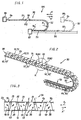
- Drag chain 90 an upper strand 91, a bow part 92 and a lower strand 93. Furthermore, the drag chain 90 with a first Connector 94 on the consumer unit 95 and with a second connector 94 'in a not shown Way either in the area of the energy source 97 on the support and guide element 96 or directly at the energy source arranged.
- the two connectors 94 and 94 ' are each at the two ends of the drag chain 90 with no closer attached means attached.
- Drag chain 90 is in Figure 1, for example, in two Positions shown.
- the drag chain 90 has movement together with the Consumer unit 95 as interrupted by the (dashed) drawn lines, such as the end position reached.
- Drag chain 90 With the movement oriented in the direction of arrow X. has that which is operatively connected to the consumer unit 95 Drag chain 90, as shown by the fully drawn lines shown, the end position has not yet been reached.
- the individual chain links together form one in the longitudinal direction the same oriented cable duct 98 for receiving at least a line member partially shown in Fig.1 110.
- the cable duct 98 is preferably for receiving a plurality of line members 110 are formed.
- the individual in the cable duct 98 insertable and on the one hand with the assigned Energy source 97 and on the other hand with the consumer unit 95 operatively connected line members 110 can in the form of a cable for electrical power supply the consumer unit and / or in the form of a flexible Hose for pneumatic and / or hydraulic energy supply of the consumer unit 95.
- the accommodation and placement of one of several electrical, pneumatic and / or hydraulic line members 110 existing combination in the drag chain 90 is also possible.
- the drag chain 90 according to the invention with the arranged in the longitudinal direction line members 110 guaranteed in relation to the fixed energy source 97 oriented in the longitudinal direction according to arrow direction X and X ' Movement of the consumer unit 95 and the unwinding movement taking place in the cable duct 98 individual line members 110 trouble-free operation.
- the trouble-free operation is also with relatively long or short movements between the fixed Energy source 97 and the consumer unit 95 and also at relatively high speeds of the floats guaranteed.
- FIG. 2 shows a section of the cable duct 98 Drag chain 90 in perspective view and in larger Scale and you can see that from a number of articulated interconnected chain links 10,30 or 80,30 formed Obertrum 91 and the bow 92 and the adjoining one Untertrum 93.
- the special training of the individual Chain links 10 and 30 and 80 respectively are shown below described in connection with Figures 3 to 6 in detail.
- Figure 2 are in the longitudinal direction the drag chain 90 seen on individual chain links 10 and 30 spaced support elements provided, which in the illustrated embodiment as laterally protruding bolts 60.60 '; 61.61'; 62.62 '; 63.63' and 64,64 'are formed.
- Using bolts 60.60 'to 64.64' is the drag chain 90 in a suitably designed Support and guide device 65 mounted linearly.
- the device 65 is used in conjunction with FIGS and 9 still described.
- FIG 4 is spatially and on a larger scale in Figure 2 by a circle K designated section in the direction of movement X, X 'slidable drag chain.
- 90 and one recognizes two spaced-apart first ones Chain links 10 and the interposed and articulated with the first two chain links 10 operatively connected second chain link 30.
- the individual chain links 10 and 30 are designed and connected to each other so that in this position (Fig.4) oriented in the longitudinal direction and by correspondingly arranged opposite side walls 20.40 and flanges 22.42 and through the cover plates 15.35 and base plates 16.36 largely closed cable duct 98 form.
- the further design of the two in essentially mirror-image chain links 10 and 30 will be described below in connection with Fig.5.
- FIG 5 is a spatial view and as an exploded view the first chain link 10 and the second chain link 30 for the drag chain 90 is shown.
- the first chain link 10 is essentially Profile-shaped in profile cross-section and includes the top cover plate 15 which is spaced in parallel for this purpose arranged base plate 16 and the cover plate 15 with the base plate 16 connecting first side wall 20.
- the one oriented vertically downward from the cover plate 15 first side wall 20 has one with respect to the bottom plate 16 wall section oriented vertically downwards 20 '.
- the leg 19 is analogous to the leg shown 19 'trained.
- At a parallel distance from the partially Wall section 20 'shown is on the opposite Side one connected to the base plate 16 and vertically downwardly oriented second side wall 21 is arranged.
- the on one side through the side wall 20 with each other connected cover plate 15 and bottom plate 16 are so in Spaced from each other that between the parts 15 and 16 a pocket 18 is provided.
- the one on the side wall 20 molded cover plate 15 has two tapered trained side edges 12 and 13, which by an orthogonal facing end edge 11 are limited.
- the Front edge 11 is preferably rounded 11 'and 11 " Mistake.
- first chain link 10 At one end of the first chain link 10 are essentially in extension of the two parallel spaced side walls 20, 20 'and 21 each two also in parallel First flanges 22, 22 'arranged at a distance from one another, one flange 22 'one on the second side wall 21 has molded leg 19 '.
- the two first flanges 22, 22 'are each formed by a bore 25 or 25 'penetrated.
- Chain link 10 becomes the second with a pivot pin 46 provided chain link 30, the bores 25, 25 'and the pivot pin 46 in assembled a second Form pivot axis B, B '(Fig.4).
- first chain link 10 At the other end of the first chain link 10 are two in second flanges arranged parallel to each other 27,27 'arranged.
- the second flanges 27, 27 ' are on that one end each with a beveled web surface 28, 28 ' and with a face edge 29, 29 'oriented perpendicularly thereto Mistake.
- FIG. 5 For example extending over the entire width of the base plate 16 Hinge pin 26, which is in axial extension on both sides with one with respect to the side walls 21 and 20 projecting, unspecified end piece is.
- the one with the two end pieces protruding to the side provided pivot pin 26 forms a first pivot axis A. for the next with correspondingly arranged bores 45 and 45 'provided second chain link 30 (Fig.4).
- the pivot pin 26 is integrally formed on the base plate 16, the Transition from the flat base plate 16 to the pivot pin 26 with one across the entire, transverse to the direction of movement oriented width of the base plate 16 extending sliding edge 17 is provided.
- the beveled in the direction of movement Sliding edge 17 is used in particular in the bent state Drag chain 90 (Fig.2) as a sliding surface for the individual or for the individual in the form of an electrical cable and / or a hose and arranged in the cable duct 98 Line members 110 (Fig.1).
- the second chain link 30, also shown in FIG. 5, is essentially analogous to the chain link described above 10 formed in the cross section of a ⁇ -shape.
- the second chain link 30 includes the top cover plate 35 which base plate 36 arranged at a parallel distance therefrom and that connects the cover plate 35 to the base plate 36 first side wall 40. Between the cover and base plate 35 and 36 a pocket 38 is provided.
- the from the cover plate 35 oriented vertically downwards to the base plate 36 first side wall 40 has one with respect to bottom plate 36 wall section 40 'oriented vertically downwards.
- At the not designated outside of the side wall 40 and the Wall portion 40 ' is a recess formed recess 34 provided, which by a vertical web 34 ' and delimits a leg 39 arranged orthogonally thereto is.
- the cover plate 35 provided with two tapered side edges 32 and 33, which is oriented by a parallel to the side wall 40 End face 31 are limited.
- the end face 31 is preferably analogous to the first chain link 10 with roundings 31 'and 31 "provided.
- the second chain link 30 At one end of the second chain link 30 are essentially in the extension of the parallel spaced side walls 40, 40 'and 41 two arranged at a parallel distance from one another arranged first flanges 42,42 ', the one Flange 42 extending in the longitudinal direction of the chain link 30 Has leg 39.
- the leg 39 of the second Chain link 30 corresponds approximately to that on the first chain link 10 arranged, not shown legs 19.
- the first chain link 10 (FIG. 4) engages with the pivot pin 26 stored.
- the second chain link 30 At the other end of the second chain link 30 are also two flanges arranged parallel to each other 47,47 'arranged.
- the two second flanges 47.47 ' are at one end each with a bevelled web surface 48.48 'and with a perpendicularly oriented Front edge 49.49 'provided.
- Hinge pin 46 forms a pivot axis B 'for the next mounted on it and with appropriately arranged holes 25, 25 'provided chain link 10.
- the pivot pin 46 is on the bottom plate 36 integrally formed, the transition from the flat bottom plate 36 to the hinge pin 46 with one over the entire, oriented transversely to the direction of movement Width of the base plate 36 extending sliding edge 37 is provided is.
- the beveled in the direction of movement Sliding edge 37 is used in particular in the bent state Drag chain 90 (Fig.2) as a sliding surface for the individual or for the individual in the form of an electrical cable and / or a hose and arranged in the cable duct 98 Line members 110 (Fig.1).
- the two Chain links 10 and 30 essentially analog and mirror images are trained.
- the first chain link 10 in Fig.5 not shown side wall 20,20 'with the Recess 14, the web 14 'and the leg 19 is analog the side wall 40, 40 'shown in FIG the recess 34, the web 34 'and the leg 39 of the second Chain link 30 formed.
- the second chain link 30 with side wall 41 not shown in FIG the leg 39 ' is analogous to that shown in FIG. 5 in view Side wall 21 with the leg 19 'of the first chain link 10 trained.
- the first are Flanges 22,22 'of the first chain link 10 and the second Flanges 47, 47 'of the second chain link 30 are arranged in this way and spaced from one another transversely to the direction of movement X, X ', that when assembled, the second, inner Flanges 47,47 'of the second chain link 30 on the inside arranged between the two spaced side walls 20 'and 21 are.
- the first two outer flanges 22, 22 ' of the first chain link 10 are on the outside of the Side walls 40, 40 and 41 arranged. Is in this position the pivot pin 46 of the second chain link 30 in the bores 25,25 'of the first chain link 10 mounted in a snap.
- Fig. 6 shows a second embodiment as a whole designated with 80 and as a spatial explosive drawing as well as a chain link shown on a larger scale.
- the chain link 80 is formed in two parts and includes a base 80 'and one relative to it, i.e., can be moved transversely to the direction of movement of the drag chain Top 80 ".
- the upper part is approximately perennial-shaped in profile cross-section 80 "has an upper cover plate 73, one at a parallel distance arranged sliding piece 76 and one of the parts 73 and 76 connecting side wall 70. That of the cover plate 73 has side wall 70 oriented vertically downwards a recess 74 formed by a Web 74 'is limited.
- the molded on the side wall 70 Cover plate 73 has two tapered side edges 72.72 ', which is rounded at the front end by a 71 ', 71 "end edge 71 are limited.
- the lower part 80 ' has a base plate 75, which by a Recess 75 'oriented transversely to the direction of movement X, X' in two sections 76 'and 76' is divided. On the two On each side of the recess 75 'there is a beveled one Flank 77 'and 78' provided. On the base plate 75 are also two side walls spaced apart 81 and 81 'molded. At one end of the lower part 80 'are an extension of the two parallel spaced Sidewalls 81,81 'two each also in parallel First flanges 82, 82 'arranged at a distance from one another, one flange 82 'one on the side wall 81 has adjoining leg 79 '.
- the first two flanges 82,82 ' are tapered at one end Web surface 83,83 'and one arranged perpendicular to it End edge 84.84 'provided.
- the first two flanges 82,82 ' are each from a bore 85 and 85 'permeated.
- the next chain link with a pivot pin (not shown) stored.
- the holes 85,85 ' form with the pivot pin of the next chain link, not shown together a swivel axis E.
- the base 80 At the other end of the base 80 'are two in parallel Flanges 87, 87 'arranged at a distance from one another.
- Farther can be seen in Figure 6, for example, over the entire Width of the base plate 75 extending hinge pin 86, which is in axial extension on both sides with one projecting with respect to the side walls 81 and 81 ', unspecified end piece is provided.
- the one with the articulated pins provided on both laterally projecting end pieces 86 accordingly forms a pivot axis F for the next one arranged holes provided chain link.
- the pivot pin 86 is integrally formed on the base plate 75, the Transition from the flat base plate 75 to the pivot pin 86 with one across the entire, transverse to the direction of transport oriented width of the base plate 75 extending sliding edge 86 'is provided
- A can also be on the sliding piece 76 Stop (not shown) are provided so that the Upper part 80 "only up to the stop from the recess 75 'of Lower part 80 'can be pulled out.
- a not shown Be arranged locking element by means of which the upper part 80 " when pushed together against unintentional pulling out is held on the lower part 80 '.
- connection between the two slidable relative to each other Sharing 80 'and 80 can also have one in itself known tongue and groove connection or the like. Essential it is here that the upper part 80 "with the sliding piece 76 relative to that provided with the recess 75 ' Lower part 80 'is slidable and pushed together State of the two parts 80 ', 80 "a flat base plate 75 is formed.
- Fig. 7 shows on a larger scale and in spatial representation the bow piece 92 and a portion of each Upper run 91 and lower run 93 of the drag chain 90 and one can see that in the area of the upper run 91 with the gap-shaped distance C and C 'arranged first and second chain links to each other 10 and 30.
- the individual chain links 10, 30 become motion in this way pivoted to each other, that between them not here specified side edges of the individual chain links 10.30 the gap-like distances C and C 'into gap-like distances D and D' as well Increase D ".
- the gap-shaped distances D" are largest, so that here the line member 110, as in FIG.
- the two outer flanges 22 and 22 'of the first chain link are in the one direction of movement by the assigned Limits 39 and 39 'of the second chain link 30 limited such that the individual chain links 10 and 30 to each other is prevented and the drag chain 90 inevitably can be deflected only in the form of the curved part 92.
- the individual elements of the two chain links 10 and 30 according to 4 to 5 each form a structural unit, the chain links 10 and 30, for example, from a suitable Plastic are injection molded. That in essential two-part chain link 80 according to Fig. 6 is also made of a suitable plastic by spraying manufactured.
- FIG 8 shows a guide rail shown in side view 50 for a sectional view shown in FIG trained to support the drag chain 90 and Guide device 65.
- the support and guide device 65 includes two with the open side against each other as well as in parallel distance to each other and in profile cross-section essentially ⁇ -shaped guide rails 50 and 50 '.
- the guide rails 50 and 50 'each have two in the vertical direction by one in the longitudinal direction Guide groove 52,52 'spaced flanges 51,51' and 53, 53 'and a web 54 connecting them to one another, 54 '.
- the lower flange 53, 53 'of the two are mutually arranged guide rails 50 and 50 ' for example, depending on the length, a number in Recesses 55, 56 and 57 spaced in the longitudinal direction are provided.
- the recesses 55, 56 and 57 are designed such that on the individual chain links 10.30 the Drag chain 90 arranged and on the lower flange 53 and 53 'overlying bolts 60 and 60', such as in Fig.9 shown at any point out of engagement of the can be brought both guide rails 50 and 50 '.
- This measure can be used in the support and guide device 65 guided drag chain 90 at any point by an arcuate deflection out of engagement of the brought both guide rails 50 and 50 '.
- the line members 110 individually or by appropriate Means bundled in the drag chain 90 threaded or stored and in the longitudinal direction thereof on at least one the bottom plates 16 and 36 of the chain links 10 and 30 attached.
- Individual base plates are for this work process with correspondingly designed recesses, not shown or provide openings. After threading and inserting of the line members 110, these are tightened in the longitudinal direction, so that this in the cable duct 98 of the drag chain 90 form a substantially straight line and approximately parallel are arranged to each other.
Landscapes
- Engineering & Computer Science (AREA)
- General Engineering & Computer Science (AREA)
- Mechanical Engineering (AREA)
- Electric Cable Arrangement Between Relatively Moving Parts (AREA)
- Steering-Linkage Mechanisms And Four-Wheel Steering (AREA)
- Pit Excavations, Shoring, Fill Or Stabilisation Of Slopes (AREA)
- Other Liquid Machine Or Engine Such As Wave Power Use (AREA)
Claims (16)
- Chaíne d'entraínement comprenant plusieurs premier et second chaínons reliés en articulation l'un à l'autre, qui possèdent un profil en section transversale approximativement en ⊂ et qui forment ensemble une gouttière de câble (98) orientée dans la direction longitudinale de la chaíne d'entraínement (90), pour la réception d'au moins un élément conducteur (110), gouttière par laquelle de l'énergie peut être acheminée à une unité de consommation (95) effectuant un mouvement linéaire de va-et-vient par rapport à une source d'énergie (97), caractérisée en ce que les chaínons (10; 30; 80) munis respectivement d'une paroi latérale (20; 40; 70), d'une plaque de recouvrement (15; 35; 73) disposée contre la première citée et d'une plaque inférieure (16; 36; 75) disposée parallèlement et à distance de la dernière citée, sont disposés respectivement de telle sorte que leurs parois latérales (20; 40; 70), par rapport à la direction longitudinale et à la direction de mouvement de la chaíne d'entraínement (90), se trouvent en alternance, sur l'un ou l'autre côté de cette dernière, et en ce que, entre les arêtes latérales (12, 32; 13, 33) des plaques de recouvrement (15; 35; 73) tournées l'une vers l'autre et orientées approximativement en direction transversale par rapport à la direction de mouvement, on prévoit respectivement un écartement (C; C') en forme de fente, dans laquelle les écartements (C; C') en forme de fentes, lors du changement de direction en forme d'arc de la chaíne d'entraínement (90), s'agrandissent en ce qui concerne la largeur de l'écartement via le mouvement relatif des chaínons (10; 30; 80) reliés l'un à l'autre et, lorsque la chaíne d'entraínement (90) est étirée de manière rectiligne, peuvent reprendre la largeur d'écartement sélectionnée à l'origine.
- Chaíne d'entraínement selon la revendication 1, caractérisée en ce que les premier et second chaínons (10; 30) sont réalisés en une seule pièce et de manière spéculaire l'un par rapport à l'autre, dans laquelle les parois latérales (20; 40) orientées dans la direction de mouvement (X, X') et formant une gouttière de câble (98) orientée dans la direction longitudinale de la chaíne d'entraínement (90), ainsi que des premières brides (22, 22'; 42, 42') montées latéralement par rapport aux parois latérales sont disposées sur l'un et l'autre côté des chaínons (10; 30).
- Chaíne d'entraínement selon la revendication 1, caractérisée en ce que le chaínon individuel (80) est réalisé en deux parties comprenant une partie inférieure (80') et une partie supérieure (80"), dans laquelle les parties inférieures individuelles (80') sont reliées l'une à l'autre en articulation et les parties supérieures individuelles (80") sont réalisées en coulissement par rapport à la partie inférieure respective (80'), en direction transversale par rapport à la direction de mouvement (X, X') de la chaíne d'entraínement (90).
- Chaíne d'entraínement selon la revendication 3, caractérisée en ce que la partie inférieure (80') présente une plaque inférieure (75) munie d'un évidement (75') orienté en direction transversale par rapport à la direction de mouvement (X, X') de la chaíne d'entraínement (90) et la partie supérieure (80") présente un coulisseau façonné (76) qui est guidé en coulissement avec des premiers flancs latéraux (77, 78) réalisés en inclinaison, dans l'évidement (75') de la partie inférieure (80') muni de seconds flancs (77', 78') réalisés en présentant une inclinaison de manière correspondante.
- Chaíne d'entraínement selon les revendications 2 à 4, caractérisée en ce que des branches (19, 19'; 39, 39') sont disposées contre les parois latérales (20, 21; 40, 41; 81, 81') des chaínons (10; 30; 80) en étant orientées dans la direction de mouvement (X, X') de la chaíne d'entraínement (90) et en étant aptes à venir se disposer en engrènement positif avec les premières brides (22, 22'; 42, 42'; 82, 82') pour empêcher la déviation angulaire des chaínons individuels.
- Chaíne d'entraínement selon la revendication 1, caractérisée en ce que les arêtes latérales (12, 13; 32, 33; 72, 72') des plaques de recouvrement (15; 35; 73) orientées approximativement en direction transversale par rapport à la direction de mouvement (X, X') sont réalisées respectivement en se rétrécissant progressivement à la manière d'un cône dans la direction d'une arête frontale (11; 31; 71) opposée à la paroi latérale (20; 40; 70) et sont disposées l'une par rapport à l'autre de telle sorte que les écartements (C; C') réalisés en forme de fentes et prévus entre les plaques de recouvrement (15; 35; 70), vu dans la direction de mouvement (X, X'), sont disposés en alternance en inclinaison réciproque.
- Chaíne d'entraínement selon la revendication 1, caractérisée en ce que chaque chaínon individuel (10; 30; 80) est muni, sur les deux extrémités orientées dans la direction de mouvement (X, X'), de deux premières et secondes brides (22, 22' et 27, 27'; 42, 42' et 47, 47'; 82, 82' et 87, 87') disposées parallèlement l'une à l'autre et à distance l'une de l'autre, dans laquelle les brides sont disposées l'une par rapport à l'autre de telle sorte que les secondes brides du second chaínon sont disposés entre les premières brides du premier chaínon, ce dernier étant monté en pivotement, par rapport au second chaínon, autour d'un axe orienté en direction transversale par rapport à la direction de mouvement (X, X').
- Chaíne d'entraínement selon les revendications 1 et 7, caractérisée en ce que les chaínons individuels (10; 30; 80) sont montés en pivotement relatif l'un par rapport à l'autre dans des alésages (25, 25'; 45, 45') des premières brides (22, 22'; 42, 42') disposés l'un par rapport à l'autre de manière correspondante, au moyen de pivots (26; 46; 86) façonnés en faisant saillie latéralement sur la plaque inférieure (16; 36; 75).
- Chaíne d'entraínement selon la revendication 6, caractérisée en ce que les secondes brides (27, 27'; 47, 47') sont munies respectivement d'une surface nervurée (28, 28'; 48, 48') chanfreinée et apte à venir se disposer en engrènement positif avec l'arête inférieure de la plaque inférieure correspondante (16; 36) lors du changement de direction en forme d'arc des chaínons (10; 30).
- Chaíne d'entraínement selon la revendication 9, caractérisée en ce que les chanfreins des surfaces nervurées (28, 28'; 48, 48'; 88, 88') sont dimensionnés en fonction du rayon de flexion (R) de la partie courbe (92) de la chaíne d'entraínement (90) et le rayon de flexion (R) est dimensionné en fonction du ou des éléments conducteurs (110) destinés à venir s'insérer dans la gouttière de câble (98).
- Chaíne d'entraínement selon la revendication 1, caractérisée en ce que la chaíne d'entraínement (90) est munie d'un nombre quelconque de paires de boulons (60, 60' à 64, 64') répartis à une certaine distance l'un de l'autre en direction longitudinale et disposés en faisant saillie latéralement sur les chaínons individuels (10; 30; 80).
- Chaíne d'entraínement selon la revendication 11, caractérisée en ce que les chaínons (10; 30; 80) sont montés au moyen des paires de boulons (60, 60' à 64, 64') entre deux rails de guidage (50, 50') disposés parallèlement l'un à l'autre et à distance l'un de l'autre, dans laquelle les rails de guidage (50, 50') présentent, sur deux brides inférieures (53, 53') orientées l'une vers l'autre, plusieurs évidements (55, 55', 56, 56', 57, 57') disposés à distance l'un de l'autre en direction longitudinale, à travers lesquels, lors du changement de direction de la chaíne d'entraínement (90), la paire de boulons (60, 60' à 64, 64') attribuée à l'évidement correspondant peut passer et se désengrener des deux brides (53, 53').
- Chaíne d'entraínement selon les revendications 11 et 12, caractérisée en ce que les paires de boulons (60, 60' à 64, 64') disposées à distance les unes des autres sur les chaínons (10; 30; 80), ainsi que les évidements (55, 55', 56, 56', 57, 57') disposés à distance sur les brides inférieures (53, 53') des rails de guidage (50, 50') sont disposés les uns par rapport aux autres de telle sorte que, lors d'une sortie de la chaíne d'entraínement (90) dans la zone de n'importe quelle paire de boulons sélectionnée (60, 60' à 64, 64'), au moins une paire de boulons montée à la suite s'appuie encore sur les brides inférieures (53, 53') et est encore guidée entre les rails de guidage (50, 50').
- Mode opératoire pour l'insertion d'au moins un élément conducteur dans la chaíne d'entraínement selon la revendication 1, caractérisé en ce que l'élément conducteur individuel (110) vient s'enfiler dans la zone de la partie courbe (92) dans la direction de mouvement (X, X') en alternance par l'un et par l'autre côté de la chaíne d'entraínement (90) et vient se poser dans la gouttière de câble (98).
- Mode opératoire selon la revendication 14, caractérisé en ce que l'enfilage et la pose de l'élément conducteur individuel (110) sont mis en oeuvre avec un mouvement simultané de déroulement dans la zone de la partie courbe (92) de la chaíne d'entraínement (90).
- Mode opératoire selon les revendications 13 à 15, caractérisé en ce que les éléments conducteurs (110) viennent s'enfiler à titre individuel ou en faisceaux à l'aide de moyens correspondants et viennent se poser, respectivement se fixer, dans la direction longitudinale de la chaíne d'entraínement (90), sur au moins une des plaques inférieures (16; 36; 75) des chaínons (10; 30; 80).
Applications Claiming Priority (4)
| Application Number | Priority Date | Filing Date | Title |
|---|---|---|---|
| CH2289/94 | 1994-07-19 | ||
| CH228994 | 1994-07-19 | ||
| CH198895 | 1995-07-09 | ||
| CH1988/95 | 1995-07-09 |
Publications (2)
| Publication Number | Publication Date |
|---|---|
| EP0693638A1 EP0693638A1 (fr) | 1996-01-24 |
| EP0693638B1 true EP0693638B1 (fr) | 1999-05-12 |
Family
ID=25689189
Family Applications (1)
| Application Number | Title | Priority Date | Filing Date |
|---|---|---|---|
| EP95110868A Expired - Lifetime EP0693638B1 (fr) | 1994-07-19 | 1995-07-12 | Chaine de support d'au moins un conducteur d'énergie et procédé d'introduction du conducteur dans la chaine |
Country Status (3)
| Country | Link |
|---|---|
| EP (1) | EP0693638B1 (fr) |
| AT (1) | ATE180046T1 (fr) |
| DE (1) | DE59505884D1 (fr) |
Cited By (1)
| Publication number | Priority date | Publication date | Assignee | Title |
|---|---|---|---|---|
| EP1074764A2 (fr) | 1999-08-06 | 2001-02-07 | Jacques Zindel | Dispositif de guidage et de support d'une chaine trainante |
Families Citing this family (5)
| Publication number | Priority date | Publication date | Assignee | Title |
|---|---|---|---|---|
| DE19644468A1 (de) * | 1996-10-25 | 1998-04-30 | Kabelschlepp Gmbh | Energieführungskette und Kettenglied mit einem starren Steg |
| FR2875065A1 (fr) * | 2004-09-03 | 2006-03-10 | Valeo Electronique Sys Liaison | Dispositif de support et de guidage de conducteurs electriques meplats |
| DE202010006220U1 (de) | 2010-04-29 | 2011-09-07 | Igus Gmbh | Endlos umlaufendes Gliederband mit Energieversorgung |
| US10367339B2 (en) | 2017-05-10 | 2019-07-30 | The Boeing Company | Snag mitigating cable track apparatus |
| CN108838690A (zh) * | 2018-09-14 | 2018-11-20 | 北京百慕合金有限责任公司 | 一种型壳切割设备 |
Family Cites Families (1)
| Publication number | Priority date | Publication date | Assignee | Title |
|---|---|---|---|---|
| GB1012432A (en) * | 1960-11-25 | 1965-12-08 | Coal Industry Patents Ltd | Means for protecting the supply cables of mining machines |
-
1995
- 1995-07-12 DE DE59505884T patent/DE59505884D1/de not_active Expired - Fee Related
- 1995-07-12 EP EP95110868A patent/EP0693638B1/fr not_active Expired - Lifetime
- 1995-07-12 AT AT95110868T patent/ATE180046T1/de not_active IP Right Cessation
Cited By (1)
| Publication number | Priority date | Publication date | Assignee | Title |
|---|---|---|---|---|
| EP1074764A2 (fr) | 1999-08-06 | 2001-02-07 | Jacques Zindel | Dispositif de guidage et de support d'une chaine trainante |
Also Published As
| Publication number | Publication date |
|---|---|
| ATE180046T1 (de) | 1999-05-15 |
| EP0693638A1 (fr) | 1996-01-24 |
| DE59505884D1 (de) | 1999-06-17 |
Similar Documents
| Publication | Publication Date | Title |
|---|---|---|
| EP0384153B1 (fr) | Chaîne porteuse pour lignes de transport d'énergie | |
| EP0343192B1 (fr) | Maillon pour chaine d'amenee d'energie | |
| WO2020148300A9 (fr) | Guidage de protection de conducteurs compacte pour des applications en salles propres, ainsi qu'unité de manchon et assemblage comprenant une chaîne d'appui pour celle-ci | |
| DE4225016A1 (de) | Kabelschleppkette | |
| EP0408967A2 (fr) | Corps d'étanchéité pour garnitures de câbles divisées longitudinalement | |
| DE2321036A1 (de) | Plattenbandfoerderer | |
| DE19703410A1 (de) | Kettenglied mit einschiebbaren Trennstegen | |
| EP3253994B1 (fr) | Maillon et chaîne de manutention à maillon | |
| WO2010029090A1 (fr) | Maillon de chaîne pour une chaîne de transmission d'énergie | |
| DE3516448C1 (de) | Energieführungskette | |
| WO2020249642A1 (fr) | Structure de guidage de ligne comportant une chaîne de support conçue pour des applications en salle blanche, et chaîne de support | |
| EP4136374A2 (fr) | Fixation d'extrémité d'une gaine flexible destinée à des applications en salle blanche | |
| DE69414101T2 (de) | Führung einer materialbahn | |
| DE2343520A1 (de) | Justierbare befestigungsstruktur | |
| DE202019100430U1 (de) | Trennsteg, Quersteg und Querboden für Energieführungsketten | |
| DE4015803C1 (en) | Link element for energy transfer chain - has height of cross-plate relative energy lines adjustable for compression of resilient packing elements and secure energy lines retention | |
| EP0693638B1 (fr) | Chaine de support d'au moins un conducteur d'énergie et procédé d'introduction du conducteur dans la chaine | |
| DE4019031C2 (de) | Vorrichtung zum Verdrehen von mittels einer Fördereinrichtung tranportierten Werkstückträgern mit Werkstücken und Verwendung einer solchen Vorrichtung | |
| DE3408912C1 (de) | Energieführungskette | |
| DE102014102626A1 (de) | Kettenglied für eine Energieführungskette | |
| DE19547215A1 (de) | Regal für Kettenglieder einer Energieführungskette | |
| WO2024213668A1 (fr) | Chaîne énergétique dotée de bandes de séparation | |
| EP0724104A1 (fr) | Elément d'atténuation de contraintes et de fixation | |
| DE102018123883A1 (de) | Energieführungskettensystem und Energieführungskette | |
| EP0794354A1 (fr) | Séparateur pour chaîne porteuse de conducteurs d'énergie |
Legal Events
| Date | Code | Title | Description |
|---|---|---|---|
| PUAI | Public reference made under article 153(3) epc to a published international application that has entered the european phase |
Free format text: ORIGINAL CODE: 0009012 |
|
| AK | Designated contracting states |
Kind code of ref document: A1 Designated state(s): AT BE CH DE ES FR GB IE IT LI NL PT SE |
|
| AX | Request for extension of the european patent |
Free format text: SI PAYMENT 950712 |
|
| RAX | Requested extension states of the european patent have changed |
Free format text: SI PAYMENT 950712 |
|
| 17P | Request for examination filed |
Effective date: 19960713 |
|
| REG | Reference to a national code |
Ref country code: CH Ref legal event code: PLI Owner name: ZINDEL CONSULTING TRANSFER- KROMBERG & SCHUBERT AG |
|
| 111L | Licence recorded |
Free format text: 960906 0100 KROMBERG & SCHUBERT AG |
|
| REG | Reference to a national code |
Ref country code: CH Ref legal event code: PLI Owner name: ZINDEL CONSULTING TRANSFER- KROMBERG & SCHUBERT AG |
|
| 17Q | First examination report despatched |
Effective date: 19970513 |
|
| GRAG | Despatch of communication of intention to grant |
Free format text: ORIGINAL CODE: EPIDOS AGRA |
|
| REG | Reference to a national code |
Ref country code: CH Ref legal event code: PLI Owner name: ZINDEL CONSULTING TRANSFER- KROMBERG & SCHUBERT AG |
|
| REG | Reference to a national code |
Ref country code: CH Ref legal event code: PLI Owner name: ZINDEL CONSULTING TRANSFER- KROMBERG & SCHUBERT AG |
|
| GRAG | Despatch of communication of intention to grant |
Free format text: ORIGINAL CODE: EPIDOS AGRA |
|
| GRAH | Despatch of communication of intention to grant a patent |
Free format text: ORIGINAL CODE: EPIDOS IGRA |
|
| GRAH | Despatch of communication of intention to grant a patent |
Free format text: ORIGINAL CODE: EPIDOS IGRA |
|
| GRAA | (expected) grant |
Free format text: ORIGINAL CODE: 0009210 |
|
| AK | Designated contracting states |
Kind code of ref document: B1 Designated state(s): AT BE CH DE ES FR GB IE IT LI NL PT SE |
|
| AX | Request for extension of the european patent |
Free format text: SI PAYMENT 19950712 |
|
| PG25 | Lapsed in a contracting state [announced via postgrant information from national office to epo] |
Ref country code: SE Free format text: THE PATENT HAS BEEN ANNULLED BY A DECISION OF A NATIONAL AUTHORITY Effective date: 19990512 Ref country code: NL Free format text: LAPSE BECAUSE OF FAILURE TO SUBMIT A TRANSLATION OF THE DESCRIPTION OR TO PAY THE FEE WITHIN THE PRESCRIBED TIME-LIMIT Effective date: 19990512 Ref country code: IT Free format text: LAPSE BECAUSE OF FAILURE TO SUBMIT A TRANSLATION OF THE DESCRIPTION OR TO PAY THE FEE WITHIN THE PRESCRIBED TIME-LIMIT;WARNING: LAPSES OF ITALIAN PATENTS WITH EFFECTIVE DATE BEFORE 2007 MAY HAVE OCCURRED AT ANY TIME BEFORE 2007. THE CORRECT EFFECTIVE DATE MAY BE DIFFERENT FROM THE ONE RECORDED. Effective date: 19990512 Ref country code: GB Free format text: LAPSE BECAUSE OF FAILURE TO SUBMIT A TRANSLATION OF THE DESCRIPTION OR TO PAY THE FEE WITHIN THE PRESCRIBED TIME-LIMIT Effective date: 19990512 Ref country code: FR Free format text: LAPSE BECAUSE OF FAILURE TO SUBMIT A TRANSLATION OF THE DESCRIPTION OR TO PAY THE FEE WITHIN THE PRESCRIBED TIME-LIMIT Effective date: 19990512 Ref country code: ES Free format text: THE PATENT HAS BEEN ANNULLED BY A DECISION OF A NATIONAL AUTHORITY Effective date: 19990512 |
|
| REF | Corresponds to: |
Ref document number: 180046 Country of ref document: AT Date of ref document: 19990515 Kind code of ref document: T |
|
| REG | Reference to a national code |
Ref country code: CH Ref legal event code: EP |
|
| REG | Reference to a national code |
Ref country code: IE Ref legal event code: FG4D Free format text: GERMAN |
|
| REF | Corresponds to: |
Ref document number: 59505884 Country of ref document: DE Date of ref document: 19990617 |
|
| PG25 | Lapsed in a contracting state [announced via postgrant information from national office to epo] |
Ref country code: IE Free format text: LAPSE BECAUSE OF NON-PAYMENT OF DUE FEES Effective date: 19990712 Ref country code: AT Free format text: LAPSE BECAUSE OF NON-PAYMENT OF DUE FEES Effective date: 19990712 |
|
| PG25 | Lapsed in a contracting state [announced via postgrant information from national office to epo] |
Ref country code: BE Free format text: LAPSE BECAUSE OF NON-PAYMENT OF DUE FEES Effective date: 19990731 |
|
| PG25 | Lapsed in a contracting state [announced via postgrant information from national office to epo] |
Ref country code: PT Free format text: LAPSE BECAUSE OF FAILURE TO SUBMIT A TRANSLATION OF THE DESCRIPTION OR TO PAY THE FEE WITHIN THE PRESCRIBED TIME-LIMIT Effective date: 19990812 |
|
| EN | Fr: translation not filed | ||
| GBV | Gb: ep patent (uk) treated as always having been void in accordance with gb section 77(7)/1977 [no translation filed] |
Effective date: 19990512 |
|
| BERE | Be: lapsed |
Owner name: ZINDEL CONSULTING Effective date: 19990731 |
|
| PLBE | No opposition filed within time limit |
Free format text: ORIGINAL CODE: 0009261 |
|
| STAA | Information on the status of an ep patent application or granted ep patent |
Free format text: STATUS: NO OPPOSITION FILED WITHIN TIME LIMIT |
|
| 26N | No opposition filed | ||
| REG | Reference to a national code |
Ref country code: IE Ref legal event code: MM4A |
|
| PGFP | Annual fee paid to national office [announced via postgrant information from national office to epo] |
Ref country code: CH Payment date: 20021002 Year of fee payment: 8 |
|
| PG25 | Lapsed in a contracting state [announced via postgrant information from national office to epo] |
Ref country code: LI Free format text: LAPSE BECAUSE OF NON-PAYMENT OF DUE FEES Effective date: 20030731 Ref country code: CH Free format text: LAPSE BECAUSE OF NON-PAYMENT OF DUE FEES Effective date: 20030731 |
|
| REG | Reference to a national code |
Ref country code: CH Ref legal event code: PL |
|
| PGFP | Annual fee paid to national office [announced via postgrant information from national office to epo] |
Ref country code: DE Payment date: 20050131 Year of fee payment: 10 |
|
| PG25 | Lapsed in a contracting state [announced via postgrant information from national office to epo] |
Ref country code: DE Free format text: LAPSE BECAUSE OF NON-PAYMENT OF DUE FEES Effective date: 20060201 |