EP0693643B1 - Soupape magnétique à modulation d'impulsions pour la commande d'un convertisseur de couple hydraudynamique d'une transmission automatique - Google Patents
Soupape magnétique à modulation d'impulsions pour la commande d'un convertisseur de couple hydraudynamique d'une transmission automatique Download PDFInfo
- Publication number
- EP0693643B1 EP0693643B1 EP95106992A EP95106992A EP0693643B1 EP 0693643 B1 EP0693643 B1 EP 0693643B1 EP 95106992 A EP95106992 A EP 95106992A EP 95106992 A EP95106992 A EP 95106992A EP 0693643 B1 EP0693643 B1 EP 0693643B1
- Authority
- EP
- European Patent Office
- Prior art keywords
- control
- pressure
- pressure connection
- chamber
- pulse width
- Prior art date
- Legal status (The legal status is an assumption and is not a legal conclusion. Google has not performed a legal analysis and makes no representation as to the accuracy of the status listed.)
- Expired - Lifetime
Links
Images


Classifications
-
- F—MECHANICAL ENGINEERING; LIGHTING; HEATING; WEAPONS; BLASTING
- F16—ENGINEERING ELEMENTS AND UNITS; GENERAL MEASURES FOR PRODUCING AND MAINTAINING EFFECTIVE FUNCTIONING OF MACHINES OR INSTALLATIONS; THERMAL INSULATION IN GENERAL
- F16H—GEARING
- F16H61/00—Control functions within control units of change-speed- or reversing-gearings for conveying rotary motion ; Control of exclusively fluid gearing, friction gearing, gearings with endless flexible members or other particular types of gearing
- F16H61/14—Control of torque converter lock-up clutches
- F16H61/143—Control of torque converter lock-up clutches using electric control means
-
- F—MECHANICAL ENGINEERING; LIGHTING; HEATING; WEAPONS; BLASTING
- F16—ENGINEERING ELEMENTS AND UNITS; GENERAL MEASURES FOR PRODUCING AND MAINTAINING EFFECTIVE FUNCTIONING OF MACHINES OR INSTALLATIONS; THERMAL INSULATION IN GENERAL
- F16H—GEARING
- F16H61/00—Control functions within control units of change-speed- or reversing-gearings for conveying rotary motion ; Control of exclusively fluid gearing, friction gearing, gearings with endless flexible members or other particular types of gearing
- F16H61/14—Control of torque converter lock-up clutches
- F16H61/143—Control of torque converter lock-up clutches using electric control means
- F16H2061/145—Control of torque converter lock-up clutches using electric control means for controlling slip, e.g. approaching target slip value
Definitions
- the invention relates to a pulse-width-modulated solenoid valve for controlling hydrodynamic torque converters, automatic gearboxes with an electromagnetic switching element and a valve body according to the preamble of patent claim 1.
- hydrodynamic torque converters As are described, for example, in EP-A-0433619 or EP-A-419782 or generally in Gerigk, Bruhn, Danner “Automobiltechnik”, Westermann-Verlag 2nd edition, 89 Pages 349 to 351 are given.
- the hydrodynamic torque converters enable smooth, jerk-free starting of the motor vehicle at low engine input shaft speeds, as well as smooth switching of the automatic transmission.
- the use of hydrodynamic torque converters results in a low-noise, low-wear and stepless transmission of the engine torque to the transmission.
- a coupling unit arranged between the pump wheel connected to the drive and the turbine wheel frictionally connects the pump wheel to the turbine wheel. This switching state is called lock-up.
- the first input is subjected to a significantly higher pressure than the second input.
- the pressure now acting in the converter housing presses the coupling device together, so that the pump wheel is non-positively connected to the turbine wheel (lock-up).
- the pressure acting at the first input of the converter is varied with the aid of the control valve.
- the hydraulic oil Since the hydraulic oil is subjected to flexing work due to the continued movement, the hydraulic oil must be constantly cooled with the aid of a cooling device which is usually arranged outside the converter.
- the branch of the hydraulic oil to the radiator is also regulated by a control valve, which is often the same that also regulates the flow of the hydraulic oil to the converter.
- control valves which are mostly pulse-width-modulated solenoid valves, as stated above.
- Pulse width modulated solenoid valves for hydrodynamic torque converters are already known.
- They comprise an electromagnetic switching element and a control valve with a control piston which is displaceably arranged therein and which closes or opens the various inputs and outputs of the control valve.
- a control pressure chamber with a plurality of inputs and outputs is arranged at the end of the valve body facing the electromagnetic switching element.
- An essentially constant control pressure of, for example, 8 bar is present at one of the inputs, the control pressure connection, which is opened and closed by the electromagnetic switching element.
- the control pressure connection is opened and the control pressure acting at the control pressure connection displaces the control piston, as a result of which a converter clutch control pressure connection connected to the control pressure chamber is released.
- the hydraulic oil flows into the converter housing via this converter clutch control pressure connection.
- the pressure acting directly at the outlet of the switching element in the control pressure chamber is between 0 bar and the maximum control pressure.
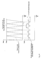
- the electrical switching element is actuated with a predetermined switching frequency of, for example, 40 Hz, the opening duration of the control pressure connection per switching pulse, the so-called pulse width, being able to be varied.
- the pulse width By changing the pulse width, the coupling device can acting control pressure between 0 bar and the maximum value to be able to specifically influence the slip acting between the pump wheel and turbine wheel. If the control pressure connection remains open over the entire pulse width, the maximum control pressure acts and the clutch remains closed, while the control pressure in the converter housing decreases accordingly with a shorter opening time.
- a switching valve for controlling a converter lock-up clutch for an automatic transmission of a motor vehicle has become known according to the preamble of claim 1.
- a solenoid generates a pulsating pressure and the valve piston is intercepted by a spring in the control pressure chamber.
- the maximum counterforce of the spring element in the direction of the electromagnetic switching element in the counter-pressure chamber approximately corresponds to the maximum control pressure acting in the control pressure chamber in order to prevent overloading of the spring element.
- disc springs have a non-linear behavior and, as the load increases, have a correspondingly disproportionately increasing counterforce. At the same time, they are able to destroy part of the kinetic energy of the control piston due to friction in the bearing surface.
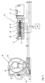
- a preferred embodiment of a pulse-modulated solenoid valve 10 according to the invention comprises an electromagnetic switching element 11 and a valve body 12.
- the valve body 12 with an end 13 facing the switching element and an end 14 facing away from the switching element has an end 14 which extends in the direction of the end 14 facing away from the switching element Slot hole on.
- the elongated hole is through depressions arranged on the circumference of the bore into a control pressure chamber 15 and two arranged at the end 13 facing the switching element adjoining working chambers 16 and 17 and a back pressure chamber 18.
- Bores 20, 21, 22, 23, 24, 25 and 26 in the valve body 12 that run perpendicular to the elongated hole serve as connections for various hydraulic oil lines.
- a counter-pressure chamber 18 is arranged, in which a plate spring 27, which prestresses the control piston 28 in the direction of the switching element 11, is accommodated.
- This plate spring 27 allows the control piston 28 to move in the lock-up.
- the control piston 28 enables the converter clutch supply pressure connection 24, at which a pressure of up to approx. 8 bar is present, to be connected via the working chamber 17 to the converter clutch counterpressure outlet 25 by means of the pressure applied to the converter clutch counterpressure outlet 25 Pressure, the clutch device 43 arranged in the torque converter 40 is opened, so that the non-positive connection between the pump wheel 41 and the turbine wheel 42 is released. Since a lower pressure is present in the line between the converter housing and the converter clutch control pressure connection 22, the hydraulic oil flows from the converter clutch back pressure connection 25 via the coupling device 43 into the converter housing and from there via the converter clutch control pressure connection 22 into the cooler 46 (unlock).
- FIG 3 shows the hydrodynamic torque converter in lock-up with the solenoid valve 10 open.
- the electromagnetic switching element 11 opens the control pressure connection 20, at which a constant pressure of, for example, 8 bar is present.
- the control piston 28 Due to the pressurized hydraulic oil flowing into the working chamber 15, the control piston 28 is displaced in the direction of the end 14 facing away from the switching element. This creates a connection between the converter clutch control pressure connection 22 and the control pressure connection 20 via the working chamber 15 Hydraulic oil under pressure from the control pressure connection 20 flows via the converter clutch control pressure connection 22 into the housing of the torque converter 40.
Landscapes
- Engineering & Computer Science (AREA)
- General Engineering & Computer Science (AREA)
- Mechanical Engineering (AREA)
- Control Of Transmission Device (AREA)
Claims (7)
- Electrovanne à modulation d'impulsions en largeur pour commander des convertisseurs de couple hydrodynamiques de transmissions automatiques, comprenant un élément électromagnétique de pilotage (11) et un corps de vanne ou de distributeur (12) qui comporte:- une chambre de pression de pilotage (15) pour un milieu fluide, présentant un raccord de pression de pilotage (20) et une sortie (21) pouvant être reliée à au moins un raccord de pression (22);- un piston ou tiroir de distribution (28) présentant au moins une gorge de distribution (29a, 29b, 29c);- au moins un deuxième raccord de pression (24, 26) reliant au moins une chambre de travail (17, 18) à au moins une sortie (23, 25); et- au moins une chambre de contre-pression (18) disposée à l'extrémité du corps de vanne (12) située à l'opposé de la chambre de pression de pilotage (15);caractérisée par:- au moins un élément élastique (27) disposé dans la chambre de contre-pression (18) et fournissant une force antagoniste pour freiner de fortes accélérations du tiroir (28);- un raccord (22) de pression de commande de l'embrayage de convertisseur, raccord qui est relié à travers la chambre de pression de pilotage (15) à la sortie (21) de la chambre de pilotage et au raccord de pression de pilotage (20);- un raccord (24) de pression d'alimentation de l'embrayage de convertisseur, raccord qui est relié à travers une première chambre de travail (16) à une sortie de refroidisseur (23); et- un raccord de pression d'alimentation (26) relié à travers une seconde chambre de travail (17) à une sortie (25) de contre-pression de l'embrayage de convertisseur,et dans laquelle au moins un raccord de pression (20, 22, 24, 26) peut être relié par une gorge de distribution (29a, 29b, 29c) à au moins une sortie (21, 23, 25), de sorte que le raccord de pression peut être relié par un solénoïde à l'alimentation menant au carter d'embrayage du convertisseur (40).
- Electrovanne à modulation d'impulsions en largeur selon la revendication 1, caractérisée en ce que le milieu fluide entrant est un milieu de pression tel que de l'huile hydraulique.
- Electrovanne à modulation d'impulsions en largeur selon une des revendications précédentes, caractérisée en ce que la force antagoniste de l'élément élastique (27), agissant en direction de l'élément électranagnétique de pilotage (11), croît à mesure que la charge augmente.
- Electrovanne à modulation d'impulsions en largeur selon une des revendications précédentes, caractérisée en ce que la force antagoniste maximale de l'élément élastique (27), agissant en direction de l'élément électromagnétique de pilotage (11), correspond à peu près à la pression de pilotage agissant au maximum dans la chambre de pression de pilotage (15).
- Electrovanne à modulation d'impulsions en largeur selon une des revendications précédentes, caractérisée en ce que l'élément élastique (27) est essentiellement en métal, céramique, matière plastique, en particulier en matière plastique renforcée par des fibres, ou en matériaux composites.
- Electrovanne à modulation d'impulsions en largeur selon une des revendications précédentes, caractérisée en ce que l'élément élastique (27) comporte au moins un ressort de compression.
- Electrovanne à modulation d'impulsions en largeur selon une des revendications 1 - 6, caractérisée en ce que l'élément élastique (27) comporte au moins une rondelle conique.
Applications Claiming Priority (2)
| Application Number | Priority Date | Filing Date | Title |
|---|---|---|---|
| DE4426147A DE4426147C2 (de) | 1994-07-22 | 1994-07-22 | Pulsweitenmoduliertes Magnetventil zum Steuern von hydrodynamischen Drehmomentwandlern automatischer Schaltgetriebe |
| DE4426147 | 1994-07-22 |
Publications (2)
| Publication Number | Publication Date |
|---|---|
| EP0693643A1 EP0693643A1 (fr) | 1996-01-24 |
| EP0693643B1 true EP0693643B1 (fr) | 1997-10-29 |
Family
ID=6523974
Family Applications (1)
| Application Number | Title | Priority Date | Filing Date |
|---|---|---|---|
| EP95106992A Expired - Lifetime EP0693643B1 (fr) | 1994-07-22 | 1995-05-09 | Soupape magnétique à modulation d'impulsions pour la commande d'un convertisseur de couple hydraudynamique d'une transmission automatique |
Country Status (3)
| Country | Link |
|---|---|
| US (1) | US5582278A (fr) |
| EP (1) | EP0693643B1 (fr) |
| DE (2) | DE4426147C2 (fr) |
Families Citing this family (5)
| Publication number | Priority date | Publication date | Assignee | Title |
|---|---|---|---|---|
| US7228783B2 (en) * | 2005-08-05 | 2007-06-12 | Gm Global Technology Operations, Inc. | Pressure control system for a torque-transmitting mechanism |
| US7746620B2 (en) * | 2008-02-22 | 2010-06-29 | Baxter International Inc. | Medical fluid machine having solenoid control system with temperature compensation |
| US7782590B2 (en) * | 2008-02-22 | 2010-08-24 | Baxter International Inc. | Medical fluid machine having solenoid control system with reduced hold current |
| US9435459B2 (en) * | 2009-06-05 | 2016-09-06 | Baxter International Inc. | Solenoid pinch valve apparatus and method for medical fluid applications having reduced noise production |
| CN115711248B (zh) * | 2022-11-24 | 2026-03-31 | 哈尔滨工业大学 | 一种变矩器用流量敏感分流控制阀 |
Family Cites Families (10)
| Publication number | Priority date | Publication date | Assignee | Title |
|---|---|---|---|---|
| DE419782C (de) * | 1924-04-05 | 1925-10-07 | Paul Haubner | Mauerstein-Reinigungsmaschine |
| DE433619C (de) * | 1925-11-04 | 1926-09-02 | Alfred Mohr | Einrichtung zur Erleichterung des Anlassens von Brennkraftmaschinen |
| US4457411A (en) * | 1980-06-02 | 1984-07-03 | Mitsubishi Jidosha Kogyo Kabushiki Kaisha | Torque transmission device |
| JPS5733254A (en) * | 1980-08-04 | 1982-02-23 | Mitsubishi Motors Corp | Torque transmitter |
| US4468988A (en) * | 1980-08-04 | 1984-09-04 | Mitsubishi Jidosha Kogyo Kabushiki Kaisha | Slip control system for a clutch |
| US4744269A (en) * | 1986-11-06 | 1988-05-17 | Ford Motor Company | Automatic transmission with lockup converter clutch controls |
| DE3928048A1 (de) * | 1989-08-25 | 1991-02-28 | Ford Werke Ag | Steuereinrichtung fuer eine ueberbrueckungskupplung eines hydrokinetischen drehmomentwandlers |
| JP2878724B2 (ja) * | 1989-09-08 | 1999-04-05 | ジャトコ株式会社 | ロックアップクラッチの油圧制御装置 |
| US5119914A (en) * | 1991-10-15 | 1992-06-09 | General Motors Corporation | Accumulator and relay valve |
| DE4328503C2 (de) * | 1992-12-03 | 2001-10-11 | Volkswagen Ag | Schaltventil |
-
1994
- 1994-07-22 DE DE4426147A patent/DE4426147C2/de not_active Expired - Fee Related
-
1995
- 1995-05-09 DE DE59500898T patent/DE59500898D1/de not_active Expired - Fee Related
- 1995-05-09 EP EP95106992A patent/EP0693643B1/fr not_active Expired - Lifetime
- 1995-05-15 US US08/440,601 patent/US5582278A/en not_active Expired - Fee Related
Also Published As
| Publication number | Publication date |
|---|---|
| DE4426147C2 (de) | 1997-03-20 |
| US5582278A (en) | 1996-12-10 |
| EP0693643A1 (fr) | 1996-01-24 |
| DE59500898D1 (de) | 1997-12-04 |
| DE4426147A1 (de) | 1996-02-01 |
Similar Documents
| Publication | Publication Date | Title |
|---|---|---|
| DE69902729T2 (de) | Stufenloses Getriebe | |
| EP1588077B1 (fr) | Dispositif de reglage d'une transmission hydrostatique | |
| DE2855085C2 (de) | Pumpenanordnung zur Versorgung von Verbrauchern mit stark schwankendem Bedarf an Druckflüssigkeit | |
| DE10323515A1 (de) | Kupplungsvorrichtung und Verfahren zum Betreiben einer Lamellenkupplung | |
| DE102004062388B4 (de) | Hydrostatischer Antrieb mit Drehzahlbegrenzung | |
| DE4424790A1 (de) | Hydrauliknotsteuerung für eine zwischen einem Verbrennungsmotor und einem Getriebe angeordnete Reibkupplung | |
| DE102015211305B3 (de) | Druckabhängig einlegbare Parksperre für hydraulisches Schaltgetriebe | |
| EP0728966B1 (fr) | Soupape de passage / commande pour convertisseurs de couple hydrodynamiques de transmissions automatiques | |
| DE2027069A1 (de) | Getriebe zur Aufrechterhaltung einer konstanten Fahrgeschwindigkeit eines Fahrzeuges | |
| EP0693643A1 (fr) | Soupape magnétique à modulation d'impulsions pour la commande d'un convertisseur de couple hydraudynamique d'une transmission automatique | |
| DE102014218555A1 (de) | Drehmomentwandlereinrichtung sowie Verfahren zum Regeln eines Flüssigkeitskreislaufs einer Drehmomentwandlereinrichtung | |
| EP0692655B1 (fr) | Soupape magnétique à modulation d'impulsions pour la commande d'un convertisseur de couple hydrodynamique d'une transmission automatique | |
| DE102020005102B4 (de) | Hydraulische Steuerung für ein Automatikgetriebe eines Fahrzeugs | |
| DD142741A1 (de) | Einrichtung zur steuerung des fluidstroms von rotationskolbenmaschinen,insbesondere zahnradpumpen | |
| WO2011085903A1 (fr) | Unité d'entraînement pour un engin de levage actionné par un milieu sous pression | |
| DE102010025243B4 (de) | Kraftwagen mit einer Lamellenkupplung | |
| DE19503549C1 (de) | Steuereinrichtung für eine schlupfsteuerbare Überbrückungskupplung für einen hydrokinetischen Drehmomentwandler | |
| DE102006032408A1 (de) | Verschleißbeständige Drehmomentwandlerkupplung mit hoher Kühlwirkung für Anwendungen mit konstantem Schlupf | |
| DE10158325A1 (de) | Hydrostatisches Antriebssystem | |
| DE10043713A1 (de) | Verfahren zur Steuerung einer hydrodynamischen Baueinheit und Steuervorrichtung | |
| DE4140860C2 (de) | Steuereinrichtung für ein hydrostatisches Getriebe | |
| DE3010913A1 (de) | Hydrostatisches antriebssystem | |
| DE4420164A1 (de) | Kombiniertes Druck- und Schaltventil | |
| DE102006006180A1 (de) | Vorrichtung zum Betreiben eines hydrodynamischen Drehmomentwandlers und einer damit korrespondierenden Wandlerüberbrückungskupplung einer Getriebeeinrichtung | |
| DE10207749A1 (de) | Antrieb |
Legal Events
| Date | Code | Title | Description |
|---|---|---|---|
| PUAI | Public reference made under article 153(3) epc to a published international application that has entered the european phase |
Free format text: ORIGINAL CODE: 0009012 |
|
| AK | Designated contracting states |
Kind code of ref document: A1 Designated state(s): DE FR GB |
|
| 17P | Request for examination filed |
Effective date: 19951209 |
|
| 17Q | First examination report despatched |
Effective date: 19961211 |
|
| GRAG | Despatch of communication of intention to grant |
Free format text: ORIGINAL CODE: EPIDOS AGRA |
|
| GRAH | Despatch of communication of intention to grant a patent |
Free format text: ORIGINAL CODE: EPIDOS IGRA |
|
| GRAH | Despatch of communication of intention to grant a patent |
Free format text: ORIGINAL CODE: EPIDOS IGRA |
|
| GRAA | (expected) grant |
Free format text: ORIGINAL CODE: 0009210 |
|
| AK | Designated contracting states |
Kind code of ref document: B1 Designated state(s): DE FR GB |
|
| REF | Corresponds to: |
Ref document number: 59500898 Country of ref document: DE Date of ref document: 19971204 |
|
| ET | Fr: translation filed | ||
| GBT | Gb: translation of ep patent filed (gb section 77(6)(a)/1977) |
Effective date: 19980116 |
|
| PLBE | No opposition filed within time limit |
Free format text: ORIGINAL CODE: 0009261 |
|
| STAA | Information on the status of an ep patent application or granted ep patent |
Free format text: STATUS: NO OPPOSITION FILED WITHIN TIME LIMIT |
|
| 26N | No opposition filed | ||
| REG | Reference to a national code |
Ref country code: FR Ref legal event code: TP Ref country code: FR Ref legal event code: CD |
|
| REG | Reference to a national code |
Ref country code: GB Ref legal event code: IF02 |
|
| PGFP | Annual fee paid to national office [announced via postgrant information from national office to epo] |
Ref country code: GB Payment date: 20030428 Year of fee payment: 9 |
|
| PGFP | Annual fee paid to national office [announced via postgrant information from national office to epo] |
Ref country code: FR Payment date: 20030512 Year of fee payment: 9 |
|
| PGFP | Annual fee paid to national office [announced via postgrant information from national office to epo] |
Ref country code: DE Payment date: 20030514 Year of fee payment: 9 |
|
| PG25 | Lapsed in a contracting state [announced via postgrant information from national office to epo] |
Ref country code: GB Free format text: LAPSE BECAUSE OF NON-PAYMENT OF DUE FEES Effective date: 20040509 |
|
| PG25 | Lapsed in a contracting state [announced via postgrant information from national office to epo] |
Ref country code: DE Free format text: LAPSE BECAUSE OF NON-PAYMENT OF DUE FEES Effective date: 20041201 |
|
| GBPC | Gb: european patent ceased through non-payment of renewal fee |
Effective date: 20040509 |
|
| PG25 | Lapsed in a contracting state [announced via postgrant information from national office to epo] |
Ref country code: FR Free format text: LAPSE BECAUSE OF NON-PAYMENT OF DUE FEES Effective date: 20050131 |
|
| REG | Reference to a national code |
Ref country code: FR Ref legal event code: ST |