EP0693664A2 - Congélateur - Google Patents
Congélateur Download PDFInfo
- Publication number
- EP0693664A2 EP0693664A2 EP95109850A EP95109850A EP0693664A2 EP 0693664 A2 EP0693664 A2 EP 0693664A2 EP 95109850 A EP95109850 A EP 95109850A EP 95109850 A EP95109850 A EP 95109850A EP 0693664 A2 EP0693664 A2 EP 0693664A2
- Authority
- EP
- European Patent Office
- Prior art keywords
- guide section
- guide
- base
- water
- section
- Prior art date
- Legal status (The legal status is an assumption and is not a legal conclusion. Google has not performed a legal analysis and makes no representation as to the accuracy of the status listed.)
- Withdrawn
Links
- XLYOFNOQVPJJNP-UHFFFAOYSA-N water Substances O XLYOFNOQVPJJNP-UHFFFAOYSA-N 0.000 claims abstract description 43
- 239000000155 melt Substances 0.000 claims description 12
- 238000000034 method Methods 0.000 claims description 5
- 238000010257 thawing Methods 0.000 claims description 4
- 238000005253 cladding Methods 0.000 claims description 3
- 230000004048 modification Effects 0.000 claims description 3
- 238000012986 modification Methods 0.000 claims description 3
- 238000011144 upstream manufacturing Methods 0.000 claims description 2
- 238000001816 cooling Methods 0.000 claims 1
- 238000005057 refrigeration Methods 0.000 abstract 1
- 238000009423 ventilation Methods 0.000 description 10
- 238000007789 sealing Methods 0.000 description 3
- 230000006978 adaptation Effects 0.000 description 2
- 238000009434 installation Methods 0.000 description 2
- 206010061217 Infestation Diseases 0.000 description 1
- 238000010276 construction Methods 0.000 description 1
- 238000011109 contamination Methods 0.000 description 1
- 238000007599 discharging Methods 0.000 description 1
- 238000006073 displacement reaction Methods 0.000 description 1
- 230000008014 freezing Effects 0.000 description 1
- 238000007710 freezing Methods 0.000 description 1
- 238000003780 insertion Methods 0.000 description 1
- 230000037431 insertion Effects 0.000 description 1
- 230000003993 interaction Effects 0.000 description 1
- 238000004519 manufacturing process Methods 0.000 description 1
- 230000000149 penetrating effect Effects 0.000 description 1
- 230000000717 retained effect Effects 0.000 description 1
- 238000003860 storage Methods 0.000 description 1
Images

Classifications
-
- F—MECHANICAL ENGINEERING; LIGHTING; HEATING; WEAPONS; BLASTING
- F25—REFRIGERATION OR COOLING; COMBINED HEATING AND REFRIGERATION SYSTEMS; HEAT PUMP SYSTEMS; MANUFACTURE OR STORAGE OF ICE; LIQUEFACTION SOLIDIFICATION OF GASES
- F25D—REFRIGERATORS; COLD ROOMS; ICE-BOXES; COOLING OR FREEZING APPARATUS NOT OTHERWISE PROVIDED FOR
- F25D21/00—Defrosting; Preventing frosting; Removing condensed or defrost water
- F25D21/14—Collecting or removing condensed and defrost water; Drip trays
-
- F—MECHANICAL ENGINEERING; LIGHTING; HEATING; WEAPONS; BLASTING
- F25—REFRIGERATION OR COOLING; COMBINED HEATING AND REFRIGERATION SYSTEMS; HEAT PUMP SYSTEMS; MANUFACTURE OR STORAGE OF ICE; LIQUEFACTION SOLIDIFICATION OF GASES
- F25D—REFRIGERATORS; COLD ROOMS; ICE-BOXES; COOLING OR FREEZING APPARATUS NOT OTHERWISE PROVIDED FOR
- F25D23/00—General constructional features
- F25D23/10—Arrangements for mounting in particular locations, e.g. for built-in type, for corner type
-
- F—MECHANICAL ENGINEERING; LIGHTING; HEATING; WEAPONS; BLASTING
- F25—REFRIGERATION OR COOLING; COMBINED HEATING AND REFRIGERATION SYSTEMS; HEAT PUMP SYSTEMS; MANUFACTURE OR STORAGE OF ICE; LIQUEFACTION SOLIDIFICATION OF GASES
- F25D—REFRIGERATORS; COLD ROOMS; ICE-BOXES; COOLING OR FREEZING APPARATUS NOT OTHERWISE PROVIDED FOR
- F25D2321/00—Details or arrangements for defrosting; Preventing frosting; Removing condensed or defrost water, not provided for in other groups of this subclass
- F25D2321/14—Collecting condense or defrost water; Removing condense or defrost water
- F25D2321/144—Collecting condense or defrost water; Removing condense or defrost water characterised by the construction of drip water collection pans
- F25D2321/1442—Collecting condense or defrost water; Removing condense or defrost water characterised by the construction of drip water collection pans outside a refrigerator
-
- F—MECHANICAL ENGINEERING; LIGHTING; HEATING; WEAPONS; BLASTING
- F25—REFRIGERATION OR COOLING; COMBINED HEATING AND REFRIGERATION SYSTEMS; HEAT PUMP SYSTEMS; MANUFACTURE OR STORAGE OF ICE; LIQUEFACTION SOLIDIFICATION OF GASES
- F25D—REFRIGERATORS; COLD ROOMS; ICE-BOXES; COOLING OR FREEZING APPARATUS NOT OTHERWISE PROVIDED FOR
- F25D2321/00—Details or arrangements for defrosting; Preventing frosting; Removing condensed or defrost water, not provided for in other groups of this subclass
- F25D2321/14—Collecting condense or defrost water; Removing condense or defrost water
- F25D2321/145—Collecting condense or defrost water; Removing condense or defrost water characterised by multiple collecting pans
-
- F—MECHANICAL ENGINEERING; LIGHTING; HEATING; WEAPONS; BLASTING
- F25—REFRIGERATION OR COOLING; COMBINED HEATING AND REFRIGERATION SYSTEMS; HEAT PUMP SYSTEMS; MANUFACTURE OR STORAGE OF ICE; LIQUEFACTION SOLIDIFICATION OF GASES
- F25D—REFRIGERATORS; COLD ROOMS; ICE-BOXES; COOLING OR FREEZING APPARATUS NOT OTHERWISE PROVIDED FOR
- F25D2321/00—Details or arrangements for defrosting; Preventing frosting; Removing condensed or defrost water, not provided for in other groups of this subclass
- F25D2321/14—Collecting condense or defrost water; Removing condense or defrost water
- F25D2321/146—Collecting condense or defrost water; Removing condense or defrost water characterised by the pipes or pipe connections
Definitions
- the invention relates to a refrigerator, in particular. Freezer, fridge and freezer combination with a base covered by a plinth covering and at least one freezer compartment which can be closed by a door and which is cooled by a defrostable evaporator if necessary, the melt water forming during the defrosting process being effective Guide length changeable, several guide sections water supply is supplied, via which the melt water can flow into the area in front of the door.
- a refrigerator which has a drain line serving to discharge melt water from its interior, which is essentially composed of two line sections.
- the line section directly discharging the melt water from the interior is formed from a downpipe penetrating a housing frame, to which a telescopically extendable drain pipe connects as a second line section, the fixed part of which is designed as an angled pipe with two legs of different lengths.
- the shorter leg of the angled pipe is coupled to the outlet-side end of the downpipe via sealing lips, during the longer leg of the angled tube serves as a support for the telescopically extendable tubular part, which cooperates on the outlet side with a locking pin which is flush on the front of the device with a base panel covering the base projection. Should it be necessary that the base projection and thus the base height have to be shortened due to any installation measures of the device, such an adjustment can only be accomplished, if at all, with complex modification measures due to the present drain line construction.
- the invention has for its object to propose a water supply according to the preamble of claim 1, with which a simple constructive structure in addition to user-friendly handling, an adaptation to different base recesses can be achieved.
- one of the sections is arranged in a fixed position on a base covering which can be adapted to different base recesses and is displaceably changeable together with this to change the effective guide length of the water supply, a continuous watercourse being generated as part of the path of change.
- a water guide that can be adapted to different base recesses in a simple manner and without complex modification measures is generated, the position of which the lead-through paneling is always retained due to the fixed arrangement of the guide section on the base paneling, thereby both the assembly process of the water guide as well as that of the plinth veneer significantly easier.
- such a solution already allows a pre-assembly of the base panel and the guide section, so that an accelerated final assembly of the base panel on the refrigerator is possible.
- the guide section on the base cladding is particularly easy to assemble and disassemble in the event of damage and thus can be replaced if, according to a further advantageous embodiment of the object of the invention, it is provided that the guide section on the base cladding is detachably latched to it.
- the melt water can be collected in a particularly user-friendly manner if, according to a next advantageous embodiment of the object of the invention, it is provided that the guide section on the base facing is followed by a further guide section serving to extend the water flow of the water guide.
- the further guide section forms the water guide together with the guide section on the base covering and a guide section arranged in front of it on the inlet side and stationary and guiding the water away from the freezer compartment.
- the individual guide sections are arranged in a cascade manner with respect to one another.
- a defined water transfer is formed between the individual guide sections without having to provide complex sealing measures to avoid leakage losses at their interfaces which result from one another.
- such a solution allows the water to be used for different base heights while maintaining the components used.
- the further guide section is displaceably guided in the adaptable plinth covering.
- Such a solution makes it particularly easy for an operator to feed the melt water flowing through the water supply to a collecting container without having to ensure that it is arranged in a narrowly prescribed prescribed collecting position.
- the guide section which can be changed by the adaptable plinth covering and the further guide section are limited in their adjustment path by stops.
- the arranged on the base panel and the further guide section are channel-shaped.
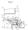
- the lower section of a kitchen unit 10 is indicated schematically, which is equipped with a recess 11 for receiving a built-in freezer 12.
- This has a freezing space 14 which can be closed by a door 13 and is conventionally thermally insulated and which is cooled by evaporator shelves which are not shown and are arranged one above the other at intervals.
- drawer-like containers 15 serving for the storage of frozen goods can be introduced, which can be removed if necessary from the freezer compartment 14, the container arranged directly above its bottom 16 serving as a collecting trough for the melt water that occurs during a defrosting process of the evaporator stages , which is fed to the collecting trough via a water duct explained in more detail below.
- the bottom 16 is equipped with an infestation, which is aligned with an outlet designed as a downpipe 17, which can be closed watertight from the side of the freezer compartment 14 with a sealing plug 18.
- the downpipe 17 penetrates the bottom 16 at its lowest point produced by the slope, the free end of the downpipe 17 facing away from the freezer compartment 14 into a wall located below the freezer compartment 14 protrudes from a base 20 enclosed base space 21, which in the present case also serves to accommodate equipment units, such as compressors, condensers or the like, which are arranged in a region remote from the door and are not shown here.
- the area of the base space 21 near the door serves to receive a water guide 22, which consists of three cascade-like ones arranged one above the other Guiding the melt water serving guide sections is formed, of which the water inlet side adjoining the free end serving as the outlet of the down pipe 17 guide section 23 is composed essentially of two cylindrical pipe sections of different cross-section.
- the shorter pipe section provided with a larger cross-section is fixed with its free end to the ceiling of the base space 21 and at the same time encloses the free end of the downpipe 17 which serves as a spout and protrudes into the base space 21, as a result of which splash water escapes into the collection space at the interface between the downpipe 17 and the guide section 23 is avoided.
- the guide section 23 opens with its free outlet-side end of its tube section with a smaller cross section into an essentially channel-shaped guide section 24 arranged underneath it, the channel bottom 25 of which is inclined with respect to a horizontal to produce a slope towards the door 13 and an outlet opening at its lowest point 26 has.
- the front ends of the channel-like guide section 24 are closed off with walls 27 and 28, the wall 28 facing the door 13 serving as the front wall having the cross-section in the form of an angular profile provided with unevenly long legs, the shorter leg of which is comb-like with elastically pivotable teeth 29 , while the longer leg of the angle profile has a retaining web 30 at its free end.
- a guide 31 designed in the manner of a pipe socket is provided above the retaining web 30 on the longer leg of the angle profile, the guide wall of which is cut free in the region of the outlet opening 26 and provided with guide cams 32 adjacent to the lateral boundary edges of the outlet opening 26.
- the guide cam 32, a stop wall 33 running parallel to the longer leg of the front wall 28 is connected upstream, which at the same time delimits the outlet opening 26.
- the front wall 28 serves to fasten the channel-shaped guide section 24 to a ventilation grille 34 which clad the base 20 on the door side and serves as a base cover and is essentially angular in cross section, on whose legs horizontally arranged in the installed position there are stop cams 35 which are in the attached state of the guide section 24 cooperates with the free ends of the teeth 29 arranged on the shorter leg of the front wall 28. Furthermore, a receptacle 36 arranged on the vertical leg is provided for fastening the guide section 24 to the ventilation grille 34, in which the holding web 30 arranged on the front wall 28 is immersed in a form-fitting manner.
- the guide section 24 is followed by a further, likewise channel-like guide section 37, the walls of which laterally delimit the water course of the channel are adapted to the radius of the pipe socket serving as guide 31 and whose wall edges facing the guide section 24 interact with the guide cams 32 in the installed state of the guide section 37 .
- the guide section 37 has a channel floor 38 inclined towards the door 13, which is provided on its outside facing away from the channel run with a wedge-like web 39 serving as a sliding surface in the guide 31.
- the web 39 is adjoined on its end face facing the base space 21 by a wall serving as a rear wall 40 for the guide section 37, which has a resilient retaining lug 41 on its side facing the web 39, the free end of which faces the guide 31 serves as a stop surface.
- a wall serving as a rear wall 40 for the guide section 37 which has a resilient retaining lug 41 on its side facing the web 39, the free end of which faces the guide 31 serves as a stop surface.
- the rear wall 40 is a wall designed as a handle 42, which is recessed on its side facing the channel bottom 38 to form an outlet opening 43 for the guide section 37 over the entire channel width.
- the height of the outlet opening 43 is dimensioned such that it enables the engagement of a finger of a hand to operate the handle 42.
- the guide section 37 is displaceably guided in the guide 31, the guide elements in addition to the web 39 which is able to slide in the guide 31 and the walls laterally delimiting the channel run also their wall edges facing the holding cams 32 and interacting with them.
- the displacement of the guide section 37 is limited in the direction of insertion into the base space 21 by the striking of the handle 42 on the stop wall 33 and in the pull-out direction by the interaction of the free end of the retaining lug 41 with the end face of the guide 31 facing them, the limiting measure for removal of the guide section 37 can be lifted out of the guide 31 by pivoting the resilient retaining lug 41 towards the web 39.
- the base of a kitchen unit 10 which is clad by a base panel 44, can have a recess of different depths opposite the front thereof.
- the ventilation grille 34 is there as well in the case of a large base recess shown in FIG adaptable in the case of a small base recess shown in FIG. 3.
- the ventilation grille 34 is displaceably guided on the appliance base 20 between stops (not shown), with its horizontal leg and the underside of the base 16 facing it, as well as a guide web 34a branching perpendicularly from its vertical leg and interacting with it, as guide elements Device base 20 serve fixedly arranged guide bracket 45.
Landscapes
- Engineering & Computer Science (AREA)
- Chemical & Material Sciences (AREA)
- Combustion & Propulsion (AREA)
- Physics & Mathematics (AREA)
- Mechanical Engineering (AREA)
- Thermal Sciences (AREA)
- General Engineering & Computer Science (AREA)
- Removal Of Water From Condensation And Defrosting (AREA)
Applications Claiming Priority (2)
| Application Number | Priority Date | Filing Date | Title |
|---|---|---|---|
| DE4425946A DE4425946A1 (de) | 1994-07-21 | 1994-07-21 | Gefriergerät |
| DE4425946 | 1994-07-21 |
Publications (2)
| Publication Number | Publication Date |
|---|---|
| EP0693664A2 true EP0693664A2 (fr) | 1996-01-24 |
| EP0693664A3 EP0693664A3 (fr) | 1996-08-14 |
Family
ID=6523851
Family Applications (1)
| Application Number | Title | Priority Date | Filing Date |
|---|---|---|---|
| EP95109850A Withdrawn EP0693664A3 (fr) | 1994-07-21 | 1995-06-23 | Congélateur |
Country Status (2)
| Country | Link |
|---|---|
| EP (1) | EP0693664A3 (fr) |
| DE (1) | DE4425946A1 (fr) |
Cited By (1)
| Publication number | Priority date | Publication date | Assignee | Title |
|---|---|---|---|---|
| EP2522937A3 (fr) * | 2011-05-10 | 2016-12-21 | BSH Hausgeräte GmbH | Dispositif de vaporisation pour un appareil frigorifique encastrable ainsi qu'appareil frigorifique encastrable et procédé d'encastrement d'un appareil frigorifique encastrable |
Citations (1)
| Publication number | Priority date | Publication date | Assignee | Title |
|---|---|---|---|---|
| DE7703184U1 (de) | 1977-02-04 | 1977-05-26 | Linde Hausgeräte Gmbh | Kühlmöbel |
Family Cites Families (3)
| Publication number | Priority date | Publication date | Assignee | Title |
|---|---|---|---|---|
| DE3514C (de) * | F. brüggemann, Tischlermeister in Magdeburg | Ablafshahn für Thauwasier bei Eisschränken | ||
| FR41387E (fr) * | 1931-11-16 | 1933-01-07 | Dispositif de récupération et d'écoulement des eaux de condensation et de fonte des glacières | |
| DE8906085U1 (de) * | 1989-05-17 | 1989-06-29 | Bosch-Siemens Hausgeräte GmbH, 8000 München | Kühlgerät, insbesondere Gefrierschrank od.dgl. |
-
1994
- 1994-07-21 DE DE4425946A patent/DE4425946A1/de not_active Withdrawn
-
1995
- 1995-06-23 EP EP95109850A patent/EP0693664A3/fr not_active Withdrawn
Patent Citations (1)
| Publication number | Priority date | Publication date | Assignee | Title |
|---|---|---|---|---|
| DE7703184U1 (de) | 1977-02-04 | 1977-05-26 | Linde Hausgeräte Gmbh | Kühlmöbel |
Cited By (1)
| Publication number | Priority date | Publication date | Assignee | Title |
|---|---|---|---|---|
| EP2522937A3 (fr) * | 2011-05-10 | 2016-12-21 | BSH Hausgeräte GmbH | Dispositif de vaporisation pour un appareil frigorifique encastrable ainsi qu'appareil frigorifique encastrable et procédé d'encastrement d'un appareil frigorifique encastrable |
Also Published As
| Publication number | Publication date |
|---|---|
| DE4425946A1 (de) | 1996-01-25 |
| EP0693664A3 (fr) | 1996-08-14 |
Similar Documents
| Publication | Publication Date | Title |
|---|---|---|
| DE69323392T2 (de) | Kühlschrank mit Zufuhrvorrichtung einer, in einer Tür angeordneten, Ausgabeeinrichtung | |
| EP0170910A1 (fr) | Appareil pour traiter des aliments à la vapeur | |
| EP0190794A2 (fr) | Réfrigérateur encastré | |
| EP1840490A2 (fr) | Appareil de réfrigération et/ou de refroidissement | |
| DE20000863U1 (de) | Kühlgerät | |
| EP2606295B1 (fr) | Un refrigerateur avec un rail de support pour une etagère | |
| DE8210690U1 (de) | Einbaugerät, insbesondere in eine Küchenzeile einbaubarer Kühl- oder Gefrierschrank | |
| EP0709631A2 (fr) | Appareil de congélation | |
| EP0693664A2 (fr) | Congélateur | |
| EP0175299B1 (fr) | Dispositif d'installation sanitaire | |
| DE8909401U1 (de) | Haushalts-Kühlgerät, insbesondere kombinierter Kühl- und Gefrierschrank | |
| DE102009028418A1 (de) | Kältegerät | |
| DE69604265T2 (de) | Kühlgerät mit einer Einrichtung zum Abführen des Tauwassers | |
| DE4420149A1 (de) | Kühlanlage mit Kühlraum, sowie Isolierpaneel mit integrierten Luftkühlerbauelementen für einen Kühlraum | |
| EP0718573A1 (fr) | Meuble, notamment meuble domestique | |
| EP0611929B1 (fr) | Appareil de refroidissement ou de congélation avec une enceinte isolée thermiquement | |
| DE8906719U1 (de) | Kühlgerät, insbesondere in eine mit einem Sockel ausgestattete Einbau-Küchenzeile einfügbarer Kühl- oder Gefrierschrank | |
| DE3503552A1 (de) | Kaeltemaschine, vorzugsweise kuehlschrank | |
| EP0936159B1 (fr) | Récipient à ordures destiné à être intégré dans un meuble | |
| WO2007115878A2 (fr) | Appareil frigorifique encastrable | |
| DE19857846A1 (de) | Kältegerät | |
| DE29805421U1 (de) | Kühlmöbel | |
| DE19537739A1 (de) | Kühltisch | |
| DE29900414U1 (de) | Kühlgerät mit verbessertem Führungselement für den Wärmeabfuhrluftstrom | |
| DE102018132042A1 (de) | Behältnisanordnung und Kältegerät mit einer Behältnisanordnung |
Legal Events
| Date | Code | Title | Description |
|---|---|---|---|
| PUAI | Public reference made under article 153(3) epc to a published international application that has entered the european phase |
Free format text: ORIGINAL CODE: 0009012 |
|
| AK | Designated contracting states |
Kind code of ref document: A2 Designated state(s): DE DK ES FR GB IT SE |
|
| PUAL | Search report despatched |
Free format text: ORIGINAL CODE: 0009013 |
|
| AK | Designated contracting states |
Kind code of ref document: A3 Designated state(s): DE DK ES FR GB IT SE |
|
| 17P | Request for examination filed |
Effective date: 19970124 |
|
| RAP1 | Party data changed (applicant data changed or rights of an application transferred) |
Owner name: BSH BOSCH UND SIEMENS HAUSGERAETE GMBH |
|
| 17Q | First examination report despatched |
Effective date: 19981026 |
|
| STAA | Information on the status of an ep patent application or granted ep patent |
Free format text: STATUS: THE APPLICATION IS DEEMED TO BE WITHDRAWN |
|
| 18D | Application deemed to be withdrawn |
Effective date: 19991231 |