EP0693996B1 - Appareil d'ajustement d'un toit ouvrant de voiture - Google Patents
Appareil d'ajustement d'un toit ouvrant de voiture Download PDFInfo
- Publication number
- EP0693996B1 EP0693996B1 EP94915082A EP94915082A EP0693996B1 EP 0693996 B1 EP0693996 B1 EP 0693996B1 EP 94915082 A EP94915082 A EP 94915082A EP 94915082 A EP94915082 A EP 94915082A EP 0693996 B1 EP0693996 B1 EP 0693996B1
- Authority
- EP
- European Patent Office
- Prior art keywords
- cover
- cam
- connecting link
- accordance
- adjustment apparatus
- Prior art date
- Legal status (The legal status is an assumption and is not a legal conclusion. Google has not performed a legal analysis and makes no representation as to the accuracy of the status listed.)
- Expired - Lifetime
Links
- 238000006073 displacement reaction Methods 0.000 claims description 17
- 230000007246 mechanism Effects 0.000 claims description 3
- 239000007787 solid Substances 0.000 claims description 3
- 230000007704 transition Effects 0.000 claims description 3
- 230000006835 compression Effects 0.000 description 7
- 238000007906 compression Methods 0.000 description 7
- 230000004075 alteration Effects 0.000 description 3
- 230000006870 function Effects 0.000 description 3
- 238000000034 method Methods 0.000 description 3
- 239000004033 plastic Substances 0.000 description 3
- 230000008859 change Effects 0.000 description 2
- 210000000078 claw Anatomy 0.000 description 2
- 239000002184 metal Substances 0.000 description 2
- 230000004048 modification Effects 0.000 description 2
- 238000012986 modification Methods 0.000 description 2
- 230000008569 process Effects 0.000 description 2
- 230000004913 activation Effects 0.000 description 1
- 230000008901 benefit Effects 0.000 description 1
- 230000015572 biosynthetic process Effects 0.000 description 1
- 230000008878 coupling Effects 0.000 description 1
- 238000010168 coupling process Methods 0.000 description 1
- 238000005859 coupling reaction Methods 0.000 description 1
- 239000011521 glass Substances 0.000 description 1
- 230000014759 maintenance of location Effects 0.000 description 1
- 238000004519 manufacturing process Methods 0.000 description 1
- 238000007789 sealing Methods 0.000 description 1
- 238000009423 ventilation Methods 0.000 description 1
Images


Classifications
-
- B—PERFORMING OPERATIONS; TRANSPORTING
- B60—VEHICLES IN GENERAL
- B60J—WINDOWS, WINDSCREENS, NON-FIXED ROOFS, DOORS, OR SIMILAR DEVICES FOR VEHICLES; REMOVABLE EXTERNAL PROTECTIVE COVERINGS SPECIALLY ADAPTED FOR VEHICLES
- B60J7/00—Non-fixed roofs; Roofs with movable panels, e.g. rotary sunroofs
- B60J7/02—Non-fixed roofs; Roofs with movable panels, e.g. rotary sunroofs of sliding type, e.g. comprising guide shoes
- B60J7/04—Non-fixed roofs; Roofs with movable panels, e.g. rotary sunroofs of sliding type, e.g. comprising guide shoes with rigid plate-like element or elements, e.g. open roofs with harmonica-type folding rigid panels
- B60J7/043—Sunroofs e.g. sliding above the roof
- B60J7/0435—Sunroofs e.g. sliding above the roof pivoting upwardly to vent mode and moving at the outside of the roof to fully open mode
-
- B—PERFORMING OPERATIONS; TRANSPORTING
- B60—VEHICLES IN GENERAL
- B60J—WINDOWS, WINDSCREENS, NON-FIXED ROOFS, DOORS, OR SIMILAR DEVICES FOR VEHICLES; REMOVABLE EXTERNAL PROTECTIVE COVERINGS SPECIALLY ADAPTED FOR VEHICLES
- B60J7/00—Non-fixed roofs; Roofs with movable panels, e.g. rotary sunroofs
- B60J7/02—Non-fixed roofs; Roofs with movable panels, e.g. rotary sunroofs of sliding type, e.g. comprising guide shoes
- B60J7/04—Non-fixed roofs; Roofs with movable panels, e.g. rotary sunroofs of sliding type, e.g. comprising guide shoes with rigid plate-like element or elements, e.g. open roofs with harmonica-type folding rigid panels
Definitions
- the invention relates to an adjustment apparatus for a sunroof that exhibits at least one cover piece for the optional closing and at least partial uncovering of a roof opening in a solid roof area of a vehicle, particularly an automobile, in which the roof opening is delimited by a base piece with side pieces that define a longitudinal direction and that lie opposite one another, and in which the cover piece is displaceable along the aforementioned longitudinal direction.
- An adjustment apparatus of this type includes at least one cover support element, one guide element for a carriage element that serves as the drive for the cover piece, and a means of control for the adjustment of the cover piece.
- the cover support element of which there is at least one, is rigidly joined with the cover piece and can be tilted (swiveled) around a first cam that runs cross-wise to the aforementioned longitudinal direction and that is placed near the front edge of the cover, and can be displaced along the aforementioned longitudinal direction by means of a cam.
- the guide element of which there is at least one, extends along the aforementioned longitudinal direction and is secured to the base piece.
- the carriage element of which there is at least one, is guided in a displaceable fashion along the aforementioned guide element and thereby along the aforementioned longitudinal direction and moves the cover piece.
- the means of control for adjusting the cover piece join the cover piece to the carriage element in a manner in which they can be moved relative to one another along the aforementioned longitudinal direction.
- spoke roof sliding roofs for vehicles, especially automobiles, that include a movable, cover-like closing element for a roof opening and are constructed in such a way that when a drive apparatus is actuated, for example, a crank, first the rear end of the closing cover raises up so that it is tilted and then, following that, the closing cover is displaced approximately horizontally while retaining the tilted position.
- a drive apparatus for example, a crank
- the area of application of the invention includes not only those sunroofs which are built in at the factory during the manufacture of the vehicle, but also those sunroofs which can be installed afterwards.
- a "spoiler roof” with an adjustment apparatus of the type described at the beginning is known from DE 33 11 452 C2.
- the transport carriage and the guide/swivel cam of the cover support element in same are rigidly placed in the frame of the sunroof, and are guided and displaced in guide elements that extend completely straight.
- the transport carriage is joined only indirectly, but not directly, with the cover support element, and specifically, by means of a swiveling lever that is controlled by the transport carriage and that is secured in a swiveling manner to the cover and to the cover support element on one side, and is guided at its opposite end in a displaceable fashion in the above-mentioned guide element.
- This lever represents a means of height adjustment at the rear and includes, in addition, a locking element that prevents the cover piece from being displaced to the rear while it is being tilted upward.
- This locking element together with the above-mentioned guide element, is used in addition to ensure that the cover that has been displaced to the rear cannot be tilted back into the closed position as it is being moved forward, but rather, only after it has reached its position of most forward movement, that is, a position in which it is completely above the opening in the roof.
- This adjustment apparatus thus requires a large number of components with complicated shapes, and to that extent, distinguishes itself little from adjustment apparatuses for other known spoiler roofs.
- a different adjustment apparatus for a "spoiler roof” is known from DE 38 01 881 C2.
- this known adjustment apparatus dispenses with one lever of the type that was described above in connection with DE 33 11 452 C2, the number of necessary components and the complexity of the shapes, as well as the multiple sequences of movements of the components, is no less than is the case in accordance with DE 33 11 452 C2, because independent components are required for holding the cover in its position of most forward movement during the tipping up of the cover and for preventing the tipping down of the cover as it is being moved forward.
- the cover support element - in contrast with the adjustment apparatus in accordance with DE 33 11 452 C2 - is not guided directly in a guide that is provided in the sunroof frame and supported by a corresponding guide cam, but instead, the cover support element is entirely supported by the transport carriage at two points that lie one behind the other, and is controlled by the transport carriage with respect to its swiveling and height adjustment movements.
- the goal of the invention consists in creating a sunroof of the type mentioned at the beginning that possesses a simply constructed system of control.
- a particular goal of the invention consists in being able to dispense with separate locking elements during the tipping movement of the cover and during the sliding movement of the cover.
- control cams are thus guided simultaneously on two guide curves that run in opposite directions and whose point of intersection uniquely defines the horizontal and vertical position of the cover support element, that is, of its cams.
- the forming of the angle by the two guide curves ensures that the transport carriage moves the cover in the desired direction with each movement of the transport carriage.
- the distance covered by the cover support element can amount, per unit of distance covered, to between 0 and 100 percent of the distance covered by the carriage.
- a spoiler roof that exhibits the invention includes a base piece that is configured as a frame 1 that is fixed in the roof and that it could be possible to retrofit, a carriage element that is configured as a transport carriage 3, and a cover piece that is configured as cover 8.
- the frame 1 is provided in order that it can be installed in a corresponding roof opening 31 in a solid roof surface 32 of a vehicle such as an automobile.
- the cover 8 is intended to close the roof opening 31, and is mounted by means of the transport carriage 3 in a manner such that it can be tilted and moved with reference to the frame 1.
- the frame 1 prescribes the horizontal plane.
- the frame 1 is essentially shaped in the form of a rectangular with rounded corners, and limits to the inside the free opening area in the vehicle roof. Near the edge of the opening, the frame 1 carries an encircling horizontal support surface 18 for the cover 8 in the form of a resilient sealing profile section.
- the frame 1 exhibits two parallel side pieces 11 that define a longitudinal direction S.
- the longitudinal direction S coincides with the direction of displacement of the cover 8.
- Each side piece 11 includes a straight, symmetrical, right/left mirror-image multifunction profile section 11', preferably made of metal.
- Formed in it are two optionally usable guide channels 12' for a drive cable 12 (shown in Fig. 3).
- the guide channel that runs in the longitudinal direction S opens, in the form of a longitudinal groove 12'', towards the inside to the multifunction profile section 11', which is - roughly speaking - U-shaped in cross-section. Because of that, a drive connection element 33 (see Fig.
- the drive cable 12 is joined - in a manner that is itself well-known - with a hand-operated crank drive, an electric motor, or a similar kind of drive mechanism, that moves the drive cable 12 back and forth in its guide channel.
- the transport carriage 3 For its guidance in a tilt-free manner, the transport carriage 3 exhibits, along the longitudinal direction S on both of its longitudinal sides, projections 3' that possess upper and lower guide surfaces 3'' and 3'''.
- a straight guide element that exhibits upper and lower guide surfaces 13a, 13b.
- the latter are formed, on the one hand, from a flat underside of a guide profile section 2' that can be inserted into the multifunction profile section 11', and on the other, from an inner surface of the multifunction profile section 11'.
- the paired guide profile 2' which is, in particular, configured as a formed plastic part, exhibits a first connecting link 2 that defines a first guide curve 2'.
- This is configured as a groove and climbs with respect to the longitudinal direction S, in a, when viewed in the direction of opening, (front) section 2''. After this, it transitions into a direction that is essentially parallel to the longitudinal direction S.
- the climb takes place at an angle of about 45°. It is perfectly possible for this climb to be steeper, even 90° if so desired, but it can also be flatter as well, for example, 40°.
- the subsequent course of the connecting link could, of course, drop off after passing through a maximum, but a course that is parallel to the longitudinal direction S or that climbs slightly is preferable.
- the manner of working of the connecting link 2 will be described in more detail in connection with the following Figures.
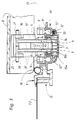
- the guide profile sections 2' are easily inserted into the recesses that are provided for them on the inner side of the edges of the multifunction profile section 11', and allow room over most of their length for the tilt-free guiding of the transport carriage by means of the side projections 3'. This can be seen especially clearly in the middle part of Fig. 4.
- the transport carriage 3 is provided with a second connecting link 5, which defines a second guide curve and is in the form of a slot.
- This slot falls (when observed from the front of the roof opening 31 in the longitudinal direction S, that is, always from the left in the drawing) very steeply at first and subsequently an a much flatter manner, namely, at an angle of about 5° relative to the longitudinal direction S.
- the course of this slot thus follows a strongly monotonic falling course in the direction of opening of the cover 8.
- the manner of working of this second connecting link will also be described in more detail later.
- the second connecting links 5 and all of the additional parts of the transport carriage 3 are configured in pairs and as mirror images of each other.
- the transport carriage 3 exhibits at its, when viewed in the direction of opening, back end, a cam 4 that is oriented at a right angle to the longitudinal direction S, that is, a pair of cams that are oriented coaxially and that face each other.
- the cam 4 is a component of a means of control, itself well-known, to bring about a change in height, and in particular, to tilt the cover 2 towards the front. To do this, the cam 4 works in conjunction with a plate-like projection 20 that is fastened to the cover 8 and with a slot 6 that is provided in the projection, in which slot the cam 4 works in the manner of an additional connecting link guide that is comprised of a connecting link pin and a connecting link groove.
- This means of control is known in all of its details from DE 38 01 881 C2, among others, and thus does not need to be explained further here.
- the cover 8 is comprised in known fashion of a flat or slightly curved panel made of metal, glass, plastic, or something similar.
- the cover 8 can be tilted, that is, swiveled, around an axis that runs transversely to the longitudinal direction S, by means of a cover support element that is rigidly joined with the cover.
- the cover support element exhibits a bracket 19' that goes vertically downward and then kinks forward at an angle.
- This is provided with a pair of first cams 7a that protrude from it sideways and that encompass the tilt axis of the cover 8. These cams are displaced in the first connecting link 2 along the first guide curve, which is determined by this connecting link.
- the cams 7a and 7b thus are all provided on a common cam 7.
- the second cams 7b can also be placed on the cover support element 19 displaced with reference to the tilt axis of the cover and thus with reference to the first cams 7a as well.
- the control of the movement of the tilt axis of the cover 8 takes place jointly by means of both cam/connecting link guides 7a, 2 and 7b, 5. This will be explained in detail later.
- the cover support element 19 also carries the above-mentioned projection 20, as well as a slot-like displacement guide 36, which is configured in pairs, for the rear end of a tension element 37, which is secured to the transport carriage 3 in a swiveling fashion, and which carries a locking part 21 that works in conjunction with a buttress 9 to lock the cover in its rear area.
- the buttress 9, which is configured in a paired fashion, can be inserted into and secured in undercut longitudinal grooves 9' at the upper end of the U-segment of the multifunction profile section 11'. It basically consists of formed plastic parts that are configured as symmetrical mirror images (see Fig. 4 in particular).
- the cam 7 engages, by means of its outer segments 7a, with both sides of the bracket 19' through the first connecting link 5 all the way into the connecting link 2, and is guided along this first connecting link 2.
- the cam sections 7b engage only with the second connecting link 5. All of the cams 7 are guided simultaneously through the first connecting link 2 and through the second connecting link 5.
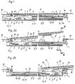
- Figs. 1, 2a and 2b The sequence of Figs. 1, 2a and 2b is made clear in principle by the geometrical arrangement of the first and second connecting links 2 and 5 relative to one another, and by the positions of the cams 7 and the various positions of the cam 4 of the means of control 4, 8 in the slot 6. For reasons of clarity, however, the function of the adjustment apparatus is shown by means of the sequence of Figs. 5a through 5e.
- first connecting link 2 and the second connecting link 5 - when viewed from the longitudinal direction S - exhibit a course of such a type that, in all of the working positions along the guide element 13a, 13b of the transport carriage 3, they form an angle A relative to the first and second cams 7a and 7b. Because of that, and because of an appropriate positioning of the first and second connecting links with each other, it is possible to achieve the fact that the positions of the cams 7a and 7b are always uniquely determined, both along the first connecting link 2 as well as along the second connecting link 5.
- first and second cams 7a and 7b are oriented coaxially, it must prevent the first and second connecting links from overlapping in a parallel oriented position at any position of the transport carriage 3, and the common cam 7 from being in this overlap area. In that event, a forward and back movement of the transport carriage would not lead to a unique cam position.
- a too-small angle A is to be avoided.
- An angle A of between 30° and 150° is as a rule completely sufficient to prevent any jamming of this nature. Greater angles, preferably between 70° and 110°, are particularly preferable. In general, the principle holds true that the bringing along of the cover support element 19 by the moving transport carriage 3 must always be ensured.
- the position of the common cam 7 for a given position of the transport carriage 3 thus must always lie at the point of intersection of the two connecting links. This prevents the cover 8 from changing its position without the transport carriage 3 being moved. In this way it is additionally ensured that the transport carriage 3 can take the cover 8 along in the rear area of connecting link 2 in which it runs horizontally, without further safety and locking measures being necessary, that is, in these cover displacement positions, the cover can be pushed forward without it tilting back into its closed position before it has reached its most forward position of displacement.
- the common cam 7 In the closed position that is shown in Fig. 1 and in Fig. 5a, the common cam 7 is located in the lowest position of the front section 2'' of the first connecting link 2. At the same time, the common cam 7 is located in the lowest position of the second connecting link 5 in the guide carriage. If, as a result of the actuation of a drive, the drive cable now begins to move the transport carriage 3 to the rear in its guide elements 13a, 13b parallel to the longitudinal direction S, it is guided by the relatively slight slope of the connecting link 5 on the one hand and the comparatively steep slope of the section 2' of the connecting link 2 on the other as a result of the fact that, in spite of a very considerable displacement of the transport carriage 3, the cover support element 19 is slightly lifted, but only very slightly moved to the rear.
- this element can carry out the tilting movement of the cover with no problem and without causing a problem.
- a pure swivel joint between the tension/compression element and the transport carriage is, of course, also conceivable.
- a cam/claw link can also be selected as the joint, in which the claw legs are long enough to remain engaged with the cam even when the front edge of the cover is raised.
- the tension/compression element can always lie parallel on the cover 8 in a displaceable fashion.
- the displacement path of the tension/compression element along the cover is only as long as the length of the connecting link 5 is, measured in the longitudinal direction S. -
- a cover lock of that type without the use of the two connecting links that are oriented at an angle to each other for the cams 7a/7b can also be used expediently and helpfully.
- the transport carriage 3 is thus the only movable functional part between its guide elements 13a, 13b and the cover 8. This not only reduces the susceptibility to failure and the play, it also makes possible an especially space-saving design.
- a first cam that is rigidly joined with the cover is guided only in the first connecting link, while the second cam is indeed likewise rigidly joined with the cover, but is displaced with regard to the first cam.
- the second connecting link does not intersect with the first connecting link in the present positions of the first and second cam, but is positioned with a parallel displacement that corresponds to the displaced cam positions.
- the second connecting link thus likewise defines a guide curve for the first cam with regard to the transport carriage on which the first cam is running, when the second cam moves from one end of the second connecting link 5 to the other end of this connecting link 5.
- the position of the first cam is determined by the point of intersection of this second guide curve with the first connecting link, while the second connecting link does not necessarily cross the first connecting link.
- connection link of the means of height alteration are allocated to the transport carriage and the cover cam that engages with it.
- the positions of the common cam and of the first and second cams, along with the positions of the first and second connecting links can be placed to the rear, and the cam and the slot of the means of height alteration can be placed to the front, that is, the two connecting link guides are thus exchanged with each other.
- the sequence of movements when opening the cover, and in particular, the transition between the individual phases opening and closing the cover can be changed or modified by means of an appropriate change in the shape of the connecting link, with nothing further being necessary.
- a sliding roof can also be implemented in which the cover is made up of a number of individual covers, each of which tilts and displaces during opening as described above. To do this, each cover piece is joined with a transport carriage in the manner described above. Alternatively, individual cover elements can also be joined with one another by means of parallelogram linkage.
Landscapes
- Engineering & Computer Science (AREA)
- Mechanical Engineering (AREA)
- Transmission Devices (AREA)
- Liquid Crystal (AREA)
- Seal Device For Vehicle (AREA)
- Power-Operated Mechanisms For Wings (AREA)
- Fittings On The Vehicle Exterior For Carrying Loads, And Devices For Holding Or Mounting Articles (AREA)
Abstract
Claims (11)
- Appareil d'ajustement d'un toit ouvrant, présentant au moins une pièce de recouvrement (8) permettant au choix de recouvrir et de découvrir au moins partiellement l'ouverture (31) d'un toit dans une zone de toit plein (32) d'un véhicule, et dans lequel l'ouverture de toit est délimitée par une pièce de base présentant des pièces latérales (11) qui définissent une direction longitudinale (S) et qui sont placées de manière opposée l'une à l'autre, et dans lequel la pièce de recouvrement (8) est déplaçable le long de la direction longitudinale (S) mentionnée précédemment,- avec au moins un élément de support de recouvrement (19) qui est solidaire de la pièce de recouvrement (8), et qui peut être incliné (pivoté) autour d'une première came (7a) qui s'étend transversalement à la direction longitudinale (S) mentionnée précédemment, et qui peut être déplacé le long de la direction longitudinale (S) mentionnée précédemment au moyen de la première came (7a),- avec au moins un élément de guidage (13a, 13b) qui s'étend le long de la direction longitudinale (S) mentionnée précédemment et est fixé à la pièce de base,- avec au moins un élément formant chariot (chariot de transport 3) qui est guidé de manière déplaçable le long de l'élément de guidage (13a, 13b) mentionné précédemment et qui déplace la pièce de recouvrement (8),- avec des moyens de commande (4 à 7) pour ajuster la pièce de recouvrement (8) qui réunit la pièce de recouvrement (8) à l'élément formant chariot (3) d'une manière où ils peuvent être déplacés l'un par rapport à l'autre et le long de la direction longitudinale (S) mentionnée précédemment,caractérisé par le faitque l'on prévoit un premier organe de liaison (2) qui s'étend fondamentalement le long de la direction longitudinale mentionnée précédemment, est fixé à la pièce de base et définit une première courbe de guidage, et dans laquelle est guidée la première came (7a),que l'élément formant chariot (3) et l'élément de support de recouvrement (19) sont réunis, au moyen d'un second organe de liaison (5) qui définit une seconde courbe de guidage et au moyen d'une seconde came (7b) qui est guidée dans le second organe de liaison (5), de telle manière que la première came (7a) se déplace le long de la seconde courbe de guidage par rapport à l'élément formant chariot (3) lorsque la seconde came (7b) est déplacée à l'intérieur du second organe de liaison (5), etque les première et seconde courbes de guidage, dans toutes les positions de travail de l'élément formant chariot (3) qui sont prévues le long de l'élément de guidage (13a, 13b), forment un angle (A) l'une avec l'autre et par rapport aux première et seconde cames (7a, 7b) de telle sorte que les positions des première et seconde cames (7a, 7b) soient toujours définies de manière unique, à la fois le long du premier organe de liaison (2) ainsi que le long du second organe de liaison (5), et que soit assuré l'entraînement le long de l'élément de support de recouvrement (19) par l'élément formant chariot (3).
- Appareil d'ajustement selon la revendication 1, caractérisé par le fait que le second organe de liaison (5) est formé dans l'élément formant chariot (3) et en ce que la seconde came (7b) est formée sur l'élément de support de recouvrement (19).
- Appareil d'ajustement selon la revendication 1 ou, de préférence, la revendication 2, caractérisé par le fait que l'angle (A) est compris entre 70° et 110°.
- Appareil d'ajustement selon l'une des revendications 1 à 3, de préférence selon la revendication 2, caractérisé par le fait que, dans une portion (2'') avant, en regardant dans la direction d'ouverture de la pièce de recouvrement (8), le premier organe de liaison monte par rapport à la direction longitudinale (S) mentionnée précédemment,
et, suite à cela, effectue une transition par rapport à une direction qui est essentiellement parallèle à la direction longitudinale (S) mentionnée précédemment. - Appareil d'ajustement selon l'une des revendications 1 à 4, de préférence selon les revendications 2 ou 4, caractérisé par le fait que le second organe de liaison (5), au moins dans une partie, suit une course tombant de manière fortemement monotone dans la direction d'ouverture du recouvrement (8).
- Appareil d'ajustement selon l'une des revendications 1 à 5, de préférence selon la revendication 2, caractérisé par le fait que les extrémités antérieures à la fois des premier et second organes de liaison (2) et (5) sont fondamentalement orientés perpendiculairement l'un à l'autre.
- Appareil d'ajustement selon l'une des revendications 1 à 6, de préférence selon la revendication 2, caractérisé par le fait qu'une came (7) forme simultanément la première came (7a) et la seconde came (7b).
- Appareil d'ajustement selon l'une des revendications 1 à 7, de préférence selon les revendications 1 ou 2, caractérisé par le fait que le chariot de transport (3) constitue la seule partie fonctionnelle mobile pour soulever et déplacer la pièce de recouvrement (8) ainsi que pour arrêter la pièce de recouvrement (8) dans sa position déplacée la plus en avant pendant le mouvement d'inclinaison au début du trajet d'ouverture, d'une part, et, d'autre part, dans sa position inclinée pendant son déplacement vers la position la plus en avant.
- Appareil d'ajustement selon l'une des revendications 1 à 8, de préférence selon les revendications 1 ou 2, présentant un mécanisme de verrouillage (21, 36, 9) qui est actionné à distance par l'élément formant chariot (3) au moyen d'un élément tendeur (37) qui présente une pièce de verrouillage (21) sur l'extrémité qui est la plus loin de l'élément formant chariot (3) et qui agit entre la pièce de recouvrement (8) et la pièce de base, caractérisé par le fait que l'élément tendeur (37) est fixé à l'élément formant chariot (3) d'une manière qui permet un mouvement de pivotement, et est maintenu, à son extrémité qui est la plus éloignée de l'élément formant chariot (3), sur la pièce de recouvrement (8) d'une manière qui permet un mouvement de déplacement.
- Appareil d'ajustement selon l'une des revendications 1 à 9, caractérisé par le fait que les parties fonctionnelles de l'appareil d'ajustement (élément de support de recouvrement 19, élément de guidage 13a, 13b, élément formant chariot 3, moyens de commande 4 à 7, premier organe de liaison 2 et, éventuellement, butée 9 et câble de commande 12) sont montées sur un profilé multi-fonction (11') rigidement ou d'une manière qui permet un mouvement de déplacement.
- Appareil d'ajustement selon l'une des revendications 1 à 10, de préférence selon les revendications 1 ou 2, caractérisé par le fait que la console (19') est inclinée totalement ou en partie dans la direction du bord avant du recouvrement par rapport à la direction longitudinale (S).
Applications Claiming Priority (3)
| Application Number | Priority Date | Filing Date | Title |
|---|---|---|---|
| DE9306187U | 1993-04-23 | ||
| DE9306187U DE9306187U1 (de) | 1993-04-23 | 1993-04-23 | Schiebedach |
| PCT/EP1994/001244 WO1994025301A1 (fr) | 1993-04-23 | 1994-04-21 | Appareil d'ajustement d'un toit ouvrant de voiture |
Publications (2)
| Publication Number | Publication Date |
|---|---|
| EP0693996A1 EP0693996A1 (fr) | 1996-01-31 |
| EP0693996B1 true EP0693996B1 (fr) | 1997-05-28 |
Family
ID=6892424
Family Applications (1)
| Application Number | Title | Priority Date | Filing Date |
|---|---|---|---|
| EP94915082A Expired - Lifetime EP0693996B1 (fr) | 1993-04-23 | 1994-04-21 | Appareil d'ajustement d'un toit ouvrant de voiture |
Country Status (6)
| Country | Link |
|---|---|
| US (2) | US5765908A (fr) |
| EP (1) | EP0693996B1 (fr) |
| AU (1) | AU6646694A (fr) |
| DE (2) | DE9306187U1 (fr) |
| MY (1) | MY110711A (fr) |
| WO (1) | WO1994025301A1 (fr) |
Families Citing this family (39)
| Publication number | Priority date | Publication date | Assignee | Title |
|---|---|---|---|---|
| AU668948B2 (en) * | 1992-07-03 | 1996-05-23 | Zani S.R.L. | Locking device for roofs of motor-vehicles or the like |
| DE9306187U1 (de) * | 1993-04-23 | 1993-11-25 | Kelm, Eckehart, 82205 Gilching | Schiebedach |
| US6056352A (en) * | 1994-07-05 | 2000-05-02 | Asc Incorporated | Sunroof assembly for an automotive vehicle and control system for operating a sunroof assembly |
| WO1996001192A1 (fr) * | 1994-07-05 | 1996-01-18 | Asc Incorporated | Ensemble toit ouvrant pour automobile et son systeme de commande |
| US5961177A (en) * | 1994-07-05 | 1999-10-05 | Asc Incorporated | Sunroof assembly drain trough for an automotive vehicle |
| US5746475A (en) * | 1995-06-07 | 1998-05-05 | Asc Incorprated | Drive mechanism for an automotive vehicle sunroof assembly |
| US6129413A (en) * | 1997-11-13 | 2000-10-10 | Asc Incorporated | Powered dual panel sunroof |
| DE29811016U1 (de) | 1998-06-19 | 1999-10-28 | Meritor Automotive GmbH, 60314 Frankfurt | Verstellvorrichtung für ein Sonnendach eines Fahrzeuges |
| DE29815104U1 (de) | 1998-08-22 | 1999-12-30 | Meritor Automotive GmbH, 60314 Frankfurt | Führungsmechanik für ein aus mindestens zwei Lamellen bestehendes Fahrzeugschiebedach |
| DE29820613U1 (de) | 1998-11-18 | 2000-03-30 | Meritor Automotive GmbH, 60314 Frankfurt | Schiebedach für Fahrzeuge |
| US6199944B1 (en) | 1999-06-04 | 2001-03-13 | Asc Incorporated | Spoiler sunroof |
| US6174025B1 (en) | 1999-08-31 | 2001-01-16 | Daimlerchrysler Corporation | Sun roof air dam wind noise reducer |
| AU2001231197A1 (en) * | 2000-01-26 | 2001-08-07 | Domino's Pizza Pmc, Inc. | Method and system for routing food orders over a computer network |
| DE10046068B4 (de) * | 2000-09-15 | 2013-03-28 | Webasto Ag | Öffnungsfähiges Fahrzeugdach |
| DE10055790B4 (de) * | 2000-11-10 | 2005-03-17 | Webasto Ag | Öffnungsfähiges Fahrzeugdach |
| DE10116620C1 (de) * | 2001-04-03 | 2002-11-21 | Webasto Vehicle Sys Int Gmbh | Verstellvorrichtung für einen Deckel eines Schiebehebedaches |
| DE10141845A1 (de) | 2001-08-27 | 2003-04-10 | Arvinmeritor Gmbh | Schiebedachsystem |
| DE10205612C2 (de) * | 2002-02-11 | 2003-12-11 | Webasto Vehicle Sys Int Gmbh | Öffnungsfähiges Fahrzeugdach |
| DE10215966B4 (de) * | 2002-04-11 | 2004-07-08 | Webasto Vehicle Systems International Gmbh | Öffnungsfähiges Fahrzeugdach |
| DE202004001916U1 (de) * | 2004-02-09 | 2004-04-08 | Arvinmeritor Gmbh | Mechanismus für ein Schiebedach |
| DE102004034463A1 (de) * | 2004-07-16 | 2006-02-16 | Arvinmeritor Gmbh | Schiebedachsystem für ein Kraftfahrzeug |
| DE102005032564B4 (de) * | 2005-07-11 | 2008-01-03 | Webasto Ag | Rahmenanordnung für die verschiebbare Lagerung eines öffnungsfähigen Fahrzeug-Dachteils |
| EP1790515A1 (fr) * | 2005-11-23 | 2007-05-30 | ArvinMeritor GmbH | Mécanisme pour soulever un toit ouvrant et un toit de véhicule avec tel mécanisme |
| US7314246B2 (en) | 2005-12-22 | 2008-01-01 | Specialty Vehicle Acquisition Corp. | Multi-panel sunroof system |
| DE102006000849B3 (de) * | 2006-01-05 | 2007-08-02 | Magna Car Top Systems Gmbh | Dach für ein Kraftfahrzeug |
| DE102006050851B4 (de) * | 2006-10-27 | 2008-08-21 | Webasto Ag | Doppelseitige Deckelanhebekulisse |
| JP4521039B2 (ja) * | 2008-02-26 | 2010-08-11 | 八千代工業株式会社 | サンルーフ装置のスライダ構造 |
| DE102009009349B4 (de) | 2009-02-18 | 2012-09-13 | Magna Car Top Systems Gmbh | Faltverdeck und Fahrzeug |
| EP2455247B1 (fr) * | 2010-11-19 | 2013-04-10 | Roof Systems Germany GmbH | Systèmes de toit coulissant |
| JP5598282B2 (ja) * | 2010-11-22 | 2014-10-01 | アイシン精機株式会社 | 車両用ルーフ装置 |
| EP2457756B1 (fr) * | 2010-11-26 | 2015-08-12 | Advanced Comfort Systems France SAS - ACS France | Pavillon vitré à panneau mobile coulissant et entrebâillant |
| FR2967942B1 (fr) * | 2010-11-26 | 2013-03-22 | Acs France Sas | Pavillon vitre a panneau mobile coulissant et entrebaillant |
| EP2607125B2 (fr) * | 2011-12-22 | 2017-03-01 | Inalfa Roof Systems Group B.V. | Mécanisme de verrouillage pour toit ouvrant et toit ouvrant dotée de celui-ci |
| JP5631944B2 (ja) * | 2012-08-22 | 2014-11-26 | 八千代工業株式会社 | サンルーフ装置 |
| JP6191407B2 (ja) * | 2013-11-08 | 2017-09-06 | アイシン精機株式会社 | サンルーフ装置 |
| JP6187171B2 (ja) * | 2013-11-08 | 2017-08-30 | アイシン精機株式会社 | サンルーフ装置 |
| US11440385B2 (en) | 2017-08-03 | 2022-09-13 | Inalfa Roof Systems Group B.V. | Open roof construction for a vehicle |
| CN112440697B (zh) | 2019-08-27 | 2023-11-24 | 英纳法天窗系统集团有限公司 | 遮阳系统及其部件的制造方法 |
| EP3795396B1 (fr) | 2019-09-19 | 2025-08-20 | Inalfa Roof Systems Group B.V. | Ensemble de guidage pour un système de toit ouvert et procédé de maintenance de l'ensemble de guidage |
Family Cites Families (14)
| Publication number | Priority date | Publication date | Assignee | Title |
|---|---|---|---|---|
| JPS58157824U (ja) * | 1982-04-16 | 1983-10-21 | ダイキヨ−・ベバスト株式会社 | 乗物の屋根窓 |
| DE3311452A1 (de) * | 1982-04-16 | 1983-10-20 | Webasto-Werk W. Baier GmbH & Co, 8035 Gauting | Hebeschiebedach |
| NL182461C (nl) * | 1982-12-30 | 1988-03-16 | Vermeulen Hollandia Octrooien | Schuifdak voor een voertuig. |
| DE3545870C2 (de) * | 1985-12-23 | 1993-12-09 | Webasto Werk Baier Kg W | Fahrzeugschiebedach |
| DE3715268A1 (de) * | 1986-07-12 | 1988-01-21 | Webasto Werk Baier Kg W | Betaetigungsvorrichtung fuer ein fahrzeugdach |
| JPH0428816Y2 (fr) * | 1987-01-22 | 1992-07-14 | ||
| JPH0341940Y2 (fr) * | 1987-01-28 | 1991-09-03 | ||
| KR930000747B1 (ko) * | 1988-07-30 | 1993-01-30 | 마쯔다 가부시기가이샤 | 자동차의 캔버스톱 |
| US5026113A (en) * | 1988-09-09 | 1991-06-25 | Sky-Top Sunroofs Ltd. | Sliding and venting sunroof |
| NL8802552A (nl) * | 1988-10-17 | 1990-05-16 | Vermeulen Hollandia Octrooien | Open-dakconstructie voor een voertuig. |
| DE3903035A1 (de) * | 1989-02-02 | 1990-08-09 | Webasto Ag Fahrzeugtechnik | Fahrzeugdach mit einem mittels eines deckels verschliessbaren dachausschnitt |
| FR2648403A1 (fr) * | 1989-06-15 | 1990-12-21 | Heuliez Henri France Design | Mecanisme d'ouverture, de fermeture et d'entrebaillement d'un panneau mobile par rapport a une surface fixe, notamment pour toit ouvrant d'un vehicule automobile |
| DE9302762U1 (de) * | 1993-02-25 | 1993-04-15 | Kelm, Eckehart, 8031 Gilching | Verstelleinrichtung für ein Hebeschiebedach |
| DE9306187U1 (de) * | 1993-04-23 | 1993-11-25 | Kelm, Eckehart, 82205 Gilching | Schiebedach |
-
1993
- 1993-04-23 DE DE9306187U patent/DE9306187U1/de not_active Expired - Lifetime
-
1994
- 1994-04-21 EP EP94915082A patent/EP0693996B1/fr not_active Expired - Lifetime
- 1994-04-21 US US08/537,684 patent/US5765908A/en not_active Expired - Lifetime
- 1994-04-21 AU AU66466/94A patent/AU6646694A/en not_active Abandoned
- 1994-04-21 DE DE69403471T patent/DE69403471T2/de not_active Expired - Fee Related
- 1994-04-21 WO PCT/EP1994/001244 patent/WO1994025301A1/fr not_active Ceased
- 1994-04-22 MY MYPI94000995A patent/MY110711A/en unknown
-
1998
- 1998-02-17 US US09/024,733 patent/US5971473A/en not_active Expired - Fee Related
Also Published As
| Publication number | Publication date |
|---|---|
| WO1994025301A1 (fr) | 1994-11-10 |
| US5971473A (en) | 1999-10-26 |
| DE9306187U1 (de) | 1993-11-25 |
| DE69403471D1 (de) | 1997-07-03 |
| DE69403471T2 (de) | 1998-03-12 |
| MY110711A (en) | 1999-01-30 |
| US5765908A (en) | 1998-06-16 |
| EP0693996A1 (fr) | 1996-01-31 |
| AU6646694A (en) | 1994-11-21 |
Similar Documents
| Publication | Publication Date | Title |
|---|---|---|
| US5765908A (en) | Adjustment apparatus for a sunroof | |
| US9186966B2 (en) | Drive system for a movable roof part of a roof module of a motor vehicle | |
| EP3034343B1 (fr) | Système de toit pour véhicule | |
| CN106467010B (zh) | 用于机动车的车顶系统 | |
| US7753438B2 (en) | Open roof construction for a vehicle | |
| EP0965469B1 (fr) | Dispositif pour le réglage d'un couvercle de toit ouvrant de véhicule automobile | |
| EP0517318B1 (fr) | Toit ouvrant relevable pour véhicule | |
| US6572183B2 (en) | Openable motor vehicle roof | |
| JPH09188141A (ja) | スライドチルトルーフ装置 | |
| EP3552853B1 (fr) | Système de toit ouvrant pour un véhicule avec glissière d'entraînement rotative | |
| EP1046529B1 (fr) | Construction de toit ouvrant pour véhicule | |
| US5358303A (en) | Roof panel for a motor vehicle | |
| CN108312817B (zh) | 电动遮光罩和天窗的结构 | |
| US7377575B2 (en) | Vehicle with retractable open top and method for stowing same, with horizontal tilting system | |
| US6959961B2 (en) | Louver vehicle roof | |
| US7393048B2 (en) | Sunshade panel apparatus | |
| EP0754583B1 (fr) | Toit coulissant et basculant, et véhicule équipé avec le toit coulissant et basculant | |
| JPH07179127A (ja) | ルーフ開閉装置 | |
| EP1494883B1 (fr) | Ensemble toit de vehicule | |
| EP1331119B1 (fr) | Véhicule avec toit levant et coulissant | |
| US4895410A (en) | Sliding and lifting roofs | |
| US20040169402A1 (en) | Vehicle roof | |
| JPH05246249A (ja) | 自動車用摺動持ち上げ屋根のためのブロッキング装置 | |
| JP2002166727A (ja) | サンルーフ装置 | |
| EP4382330A1 (fr) | Système de toit pour véhicule |
Legal Events
| Date | Code | Title | Description |
|---|---|---|---|
| PUAI | Public reference made under article 153(3) epc to a published international application that has entered the european phase |
Free format text: ORIGINAL CODE: 0009012 |
|
| 17P | Request for examination filed |
Effective date: 19951013 |
|
| AK | Designated contracting states |
Kind code of ref document: A1 Designated state(s): DE FR GB IT NL |
|
| GRAG | Despatch of communication of intention to grant |
Free format text: ORIGINAL CODE: EPIDOS AGRA |
|
| GRAH | Despatch of communication of intention to grant a patent |
Free format text: ORIGINAL CODE: EPIDOS IGRA |
|
| 17Q | First examination report despatched |
Effective date: 19961024 |
|
| GRAH | Despatch of communication of intention to grant a patent |
Free format text: ORIGINAL CODE: EPIDOS IGRA |
|
| GRAA | (expected) grant |
Free format text: ORIGINAL CODE: 0009210 |
|
| RAP1 | Party data changed (applicant data changed or rights of an application transferred) |
Owner name: FARMONT GMBH |
|
| RIN1 | Information on inventor provided before grant (corrected) |
Inventor name: KELM, ECKEHART |
|
| AK | Designated contracting states |
Kind code of ref document: B1 Designated state(s): DE FR GB IT NL |
|
| REF | Corresponds to: |
Ref document number: 69403471 Country of ref document: DE Date of ref document: 19970703 |
|
| ET | Fr: translation filed | ||
| PLBE | No opposition filed within time limit |
Free format text: ORIGINAL CODE: 0009261 |
|
| STAA | Information on the status of an ep patent application or granted ep patent |
Free format text: STATUS: NO OPPOSITION FILED WITHIN TIME LIMIT |
|
| 26N | No opposition filed | ||
| REG | Reference to a national code |
Ref country code: GB Ref legal event code: IF02 |
|
| PGFP | Annual fee paid to national office [announced via postgrant information from national office to epo] |
Ref country code: GB Payment date: 20030416 Year of fee payment: 10 |
|
| PG25 | Lapsed in a contracting state [announced via postgrant information from national office to epo] |
Ref country code: GB Free format text: LAPSE BECAUSE OF NON-PAYMENT OF DUE FEES Effective date: 20040421 |
|
| GBPC | Gb: european patent ceased through non-payment of renewal fee |
Effective date: 20040421 |
|
| PGFP | Annual fee paid to national office [announced via postgrant information from national office to epo] |
Ref country code: IT Payment date: 20060430 Year of fee payment: 13 |
|
| PGFP | Annual fee paid to national office [announced via postgrant information from national office to epo] |
Ref country code: NL Payment date: 20090405 Year of fee payment: 16 Ref country code: FR Payment date: 20090417 Year of fee payment: 16 Ref country code: DE Payment date: 20090420 Year of fee payment: 16 |
|
| PG25 | Lapsed in a contracting state [announced via postgrant information from national office to epo] |
Ref country code: IT Free format text: LAPSE BECAUSE OF NON-PAYMENT OF DUE FEES Effective date: 20070421 |
|
| REG | Reference to a national code |
Ref country code: NL Ref legal event code: V1 Effective date: 20101101 |
|
| REG | Reference to a national code |
Ref country code: FR Ref legal event code: ST Effective date: 20101230 |
|
| PG25 | Lapsed in a contracting state [announced via postgrant information from national office to epo] |
Ref country code: NL Free format text: LAPSE BECAUSE OF NON-PAYMENT OF DUE FEES Effective date: 20101101 |
|
| PG25 | Lapsed in a contracting state [announced via postgrant information from national office to epo] |
Ref country code: DE Free format text: LAPSE BECAUSE OF NON-PAYMENT OF DUE FEES Effective date: 20101103 |
|
| PG25 | Lapsed in a contracting state [announced via postgrant information from national office to epo] |
Ref country code: FR Free format text: LAPSE BECAUSE OF NON-PAYMENT OF DUE FEES Effective date: 20100430 |