EP0694249B1 - Ballen-Lade-Wagen um Ballen an eine Wickelvorrichtung abzugeben - Google Patents
Ballen-Lade-Wagen um Ballen an eine Wickelvorrichtung abzugeben Download PDFInfo
- Publication number
- EP0694249B1 EP0694249B1 EP95450011A EP95450011A EP0694249B1 EP 0694249 B1 EP0694249 B1 EP 0694249B1 EP 95450011 A EP95450011 A EP 95450011A EP 95450011 A EP95450011 A EP 95450011A EP 0694249 B1 EP0694249 B1 EP 0694249B1
- Authority
- EP
- European Patent Office
- Prior art keywords
- trailer
- ramp
- bales
- agricultural device
- longitudinal axis
- Prior art date
- Legal status (The legal status is an assumption and is not a legal conclusion. Google has not performed a legal analysis and makes no representation as to the accuracy of the status listed.)
- Expired - Lifetime
Links
- 239000012530 fluid Substances 0.000 claims description 3
- 230000008878 coupling Effects 0.000 claims description 2
- 238000010168 coupling process Methods 0.000 claims description 2
- 238000005859 coupling reaction Methods 0.000 claims description 2
- 235000013580 sausages Nutrition 0.000 description 8
- 238000013459 approach Methods 0.000 description 5
- 230000006872 improvement Effects 0.000 description 3
- 239000000463 material Substances 0.000 description 3
- 238000013519 translation Methods 0.000 description 3
- 238000004804 winding Methods 0.000 description 3
- 238000006243 chemical reaction Methods 0.000 description 2
- 230000000694 effects Effects 0.000 description 2
- 239000002985 plastic film Substances 0.000 description 2
- 229920006255 plastic film Polymers 0.000 description 2
- 230000009467 reduction Effects 0.000 description 2
- 241001080024 Telles Species 0.000 description 1
- 238000004891 communication Methods 0.000 description 1
- 239000000470 constituent Substances 0.000 description 1
- 230000002542 deteriorative effect Effects 0.000 description 1
- 238000010586 diagram Methods 0.000 description 1
- 238000006073 displacement reaction Methods 0.000 description 1
- 210000003108 foot joint Anatomy 0.000 description 1
- 238000009434 installation Methods 0.000 description 1
- 238000012423 maintenance Methods 0.000 description 1
- 239000004033 plastic Substances 0.000 description 1
- 238000012545 processing Methods 0.000 description 1
- 238000005096 rolling process Methods 0.000 description 1
- 238000000926 separation method Methods 0.000 description 1
- 239000004460 silage Substances 0.000 description 1
- 239000010902 straw Substances 0.000 description 1
- 230000001360 synchronised effect Effects 0.000 description 1
- 238000012546 transfer Methods 0.000 description 1
Images


Classifications
-
- A—HUMAN NECESSITIES
- A01—AGRICULTURE; FORESTRY; ANIMAL HUSBANDRY; HUNTING; TRAPPING; FISHING
- A01D—HARVESTING; MOWING
- A01D90/00—Vehicles for carrying harvested crops with means for selfloading or unloading
- A01D90/02—Loading means
- A01D90/08—Loading means with bale-forming means additionally used for loading; with means for picking-up bales and transporting them into the vehicle
- A01D90/083—Round-bale trailers
Definitions
- the present invention relates to a device for collecting, transporting bales and feeding a continuous wrapper with the bales thus collected.
- a wrapper comprises, in known manner, a platform feed on which a ball is placed picked up in the field using a fork which is equipped a tractor, said bale being pushed by a jack usually to pass it through a ring wrapping which simply includes an unwinder automatic film.
- the ball is pushed to the other side of the ring as it is wound up by the film, the speed of advance and the speed of unwinding of the film being synchronized to get the desired result and in particular a good superposition of the film layers.
- a second ball is placed on the receiving platform and receives the thrust from the cylinder, which has the effect of pass the second bale through the wrapping ring but also to push the first ball since the second ball comes to rest on the first to make a sausage continuous fodder and / or straw.
- the chassis that supports the wrapper is mounted on wheels to be able to move it and usually includes a evacuation platform, adjacent to the wrapping ring and inclined to close proximity to the ground, which receives the sausage as it is formed.
- This platform discharge includes rollers that allow the sausage, the outer surface of which is a plastic film, to translate the film without a hitch.
- the pusher moves the trailer by reaction the wrapper, so that the sausage stays in place while the trailer backs up, which prevents the sausage, therefore the film, on the ground.
- Some wrappers include a motorization integrated which delivers the hydraulic power necessary for the operation of the various actuating members, in particular the push cylinder and automatic film unwinder.
- the wrapper must be put into service and simultaneously feed it in bales, which forces the operator with numerous ascents and descents of his headquarters or use of dedicated additional staff to this simple operation.
- the device according to the invention has numerous advantages because it allows a reduction of the material necessary, a reduction in prices and costs of operation of the materials used, a decrease in staff serving and improving the working conditions of this staff. Above all, it allows very high speed execution of the operation, in optimal conditions of storage of products.
- One of the ramps is pivotally mounted about an axis parallel to the longitudinal axis of the trailer and in the immediate vicinity of the separator, provided with means of maneuver so that the ramp can take a first low position parallel to the platform and a second position inclined relative to the plate, towards the juxtaposed ramp.
- the ramp can be inclined and fixed.
- the trailer comprises a ramp single equipped with rollers as well as means of movement of balls including a closed loop chain stretched between two capstans on either side of the axis median longitudinal of the trailer, said carrying chain, regularly spaced, ball push bars.
- the loading means comprise a fork provided with teeth, parallel to the longitudinal axis of the trailer, fixed on arms perpendicular to the axis longitudinal of the trailer. These arms are provided with means of maneuver and pivotally mounted about an axis parallel to the longitudinal axis of the trailer, between a first position in which the fork comes to ground level and a second position in which the arms are raised.
- An improvement of this trailer provides for fluid connectors adapted to cooperate with conjugate connectors arranged on the wrapper, said connectors being provided for connection / disconnection automatic.
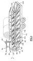
- Figure 1 there is shown a wrapper simplified which includes the various elements necessary different functions without attaching importance to accessories necessary for the complete realization and industrial of such a machine.
- a chassis 10, mounted on wheels 12 includes a platform feed 14, a wrapping ring 16 and a evacuation platform 18.
- the feed platform 14 includes a tray 20 on which the ball 22 is deposited, as shown, but also a jack 24 for pushing said ball to through the wrapping ring 16.
- Pads 28 guide the ball and prevents it from rolling sideways.
- the wrapping ring 16 includes a fixed support annular 30 secured to the chassis and guyed, in which turns a carriage 32 carrying a film reel 34 with the tension rollers required 36.
- a hydraulic motor is shown at 38, it ensures the rotation of the carriage along the annular fixed support 30, more particularly the rotation of a second annular support (not shown), coaxial to the first and guided by it, the carriage 32 being integral with this second support.
- a pad 40 also provides guidance at the outlet of the wrapping ring 16.
- the evacuation platform 18 includes a ramp 42, tilted or tiltable, equipped with rollers 44 allowing the translation of the bale roll, wrapped.
- the device according to the invention comprises a trailer 50, with a plate 52 mounted on wheels 54 and equipped with a adjustable hitch 56 and loading means 58.
- the plate 52 in this first embodiment, includes two ramps 60 and 62, juxtaposed and parallel to each other, along the longitudinal axis of the trailer, axis coincides with the direction of movement imposed by the wheels.
- the ramp 62 arranged on the left, is fixed relative to the trailer bed.
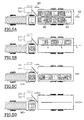
- the separator which includes an inverted V above which facilitates the separation of the balls of the one and the other row and which makes easier to raise said separator.
- Each corridor further comprises maneuvering means bullets located on the right 76 and on the left 78, symbolically represented by a jack for the operating means 76 to straight and by a broken line for the means of operation 78 which include a chain with a plate forming a pusher, such a chain being well known in the art earlier and also used in the variant which will be described later.
- the coupling 56 includes a drawbar 80 of known type but it is pivotable and equipped with orientation means 82 in the horizontal plane in order to offset the tractive effort.
- orientation means 82 comprise a jack whose retracted position of the piston corresponds to the normal position of the drawbar in position central parallel to the longitudinal axis of the trailer and the position of the piston corresponds to an angulation of the drawbar to the right side which clears the space in front of the left corridor 62.
- the operator stops when the bale is placed on the teeth and by actuating the jack 92, it raises the arms so the ball rolls and comes to rest on the separator which is in the raised position, forming a stop.
- the first ball is therefore at the head of the first ramp 60.
- the operator moves to another ball again and during this displacement, it positions the ball which comes to be loaded towards the rear of the ramp 60 by actuating the means 76.
- the wrapper is stopped and the tractor-trailer combination is separated from the wrapper so that the operator goes through a new cycle.
- FIG. 4 the means of loading 58 are identical but the tray is arranged differently. Indeed there is a chain 100, stretched between two capstans front 101 and rear 102. The chain is arranged in the central area and each of its strands is fitted with 104 push bars which are regularly distributed along the chain and planned to cooperate by thrust with bullets.
- the platform includes a U-shaped ramp 106, the branches correspond to ramps 60 and 62 of the previous achievement.
- This embodiment allows by means of a chain unique to circulate the balls one by one as soon as they are removed on the trailer by the arms 88 which remain unchanged by compared to the previous embodiment.
- Improvements are possible from these embodiments and in particular one can provide for connect, for each wrapping cycle, the hydraulics of the tractor, wrapper, which avoids the installation of a particular motorization and its maintenance especially that use is very sporadic. This is generally not not very desirable for heat engines.
- tilting ramp has been provided 60, but this ramp can be fixed and tilted in permanence.
- Another variant consists in resorting to the minus one cylinder, oriented transversely, which is equipped with a pusher and can thus transfer balls from a ramp to the other.
- the ramps are drawn like plates but it is possible to provide shaped cradles, provided for cooperate best with the balls.
- the tilt is, in this case, obtained by a pivoting of the two cradles one by report with a retraction of the central part comprising, for example, articulated links.
Landscapes
- Life Sciences & Earth Sciences (AREA)
- Environmental Sciences (AREA)
- Storage Of Harvested Produce (AREA)
- Basic Packing Technique (AREA)
- Agricultural Machines (AREA)
Claims (8)
- Landwirtschaftliches Gerät, das mit Hilfe eines Traktors bewegbar ist und mit einer Hydraulikzentrale versehen ist, umfassend einen Anhänger (50), der mit Mitteln (58) zum Aufladen von durch eine Ballenpresse hergestellten Ballen, wenigstens einer Rampe (60, 62, 106), die dazu vorgesehen ist, diese Ballen aufzunehmen, und Mitteln zum Verschieben dieser Ballen auf der Rampe versehen ist, wobei sich das Gerät für die ununterbrochene Beschickung einer Umbandelungsmaschine mit den auf diese Weise gesammelten und transportierten Ballen eignet, dadurch gekennzeichnet, daß der Anhänger zwei nebeneinander angeordnete Rampen (60, 62), die zur Längsachse des Anhängers parallel sind, sowie eine mittige Trennvorrichtung (72) umfaßt, wobei seitliche Geländer (68, 70) zum Halten und Führen der auf diesen Rampen angeordneten Ballen von vorn nach hinten bzw. von hinten nach vorn vorgesehen sind.
- Landwirtschaftliches Gerät nach Anspruch 1, dadurch gekennzeichnet, daß der Anhänger eine Kupplung (56) mit einer orientierbaren Deichsel (80) umfaßt.
- Landwirtschaftliches Gerät nach Anspruch 1 oder 2, dadurch gekennzeichnet, daß eine der Rampen (60) schwenkbar um eine zur Längsachse des Anhängers parallele Achse (66) und in direkter Nähe der Trennvorrichtung (72) angebracht ist und mit Betätigungsmitteln (74) versehen ist, damit die Rampe eine erste untere Position parallel zur Plattform und eine zweite Position, die in bezug auf die Plattform zu der daneben befindlichen Rampe (62) geneigt ist, einnehmen kann.
- Landwirtschaftliches Gerät nach Anspruch 1 oder 2, dadurch gekennzeichnet, daß eine der Rampen (60) so angebracht ist, daß sie quer zu der daneben angeordneten Rampe in der festen Position geneigt ist.
- Landwirtschaftliches Gerät nach Anspruch 1 oder 2, dadurch gekennzeichnet, daß der Anhänger eine einzige U-förmige Rampe (106) umfaßt, die mit Rollen sowie mit Mitteln zum Bewegen der Ballen ausgerüstet ist, die eine Kette (100) in geschlossener Schleife umfassen, die zwischen zwei Antriebsrollen (101, 102) beiderseits der mittigen Längsachse des Anhängers gespannt ist und in regelmäßigen Abständen Schubstäbe (104) für die Ballen trägt.
- Landwirtschaftliches Gerät nach einem der vorhergehenden Ansprüche, dadurch gekennzeichnet, daß die Beladungsmittel (58) eine Gabel (84) umfassen, die mit Zähnen (86) versehen ist, die zur Längsachse des Anhängers parallel sind und an Armen (88) befestigt sind, die zur Längsachse des Anhängers senkrecht sind, mit Betätigungsmitteln (92) versehen sind und so angebracht sind, daß sie um eine zur Längsachse des Anhängers parallele Achse (90) zwischen einer ersten Position, in der die Gabel (84) die Höhe des Bodens erreicht, und einer zweiten Position, in der die Arme (88) angehoben sind, schwenkbar sind.
- Landwirtschaftliches Gerät nach einem der vorhergehenden Ansprüche, dadurch gekennzeichnet, daß der Anhänger Fluidverbinder (108) umfaßt, die so beschaffen sind, daß sie mit zugehörigen Verbindern, die an der Umbandelungsmaschine angeordnet sind, zusammenwirken, wobei diese Verbinder für einen automatischen Anschluß/eine automatische Trennung vorgesehen sind.
- Landwirtschaftliches Gerät nach einem der vorhergehenden Ansprüche, dadurch gekennzeichnet, daß die mittige Trennvorrichtung (72) in ihrem oberen Abschnitt ein umgekehrtes V aufweist.
Applications Claiming Priority (4)
| Application Number | Priority Date | Filing Date | Title |
|---|---|---|---|
| FR9409406A FR2722943A1 (fr) | 1994-07-27 | 1994-07-27 | Remorque autochargeuse de balles cylindriques de fourrage |
| FR9409406 | 1994-07-27 | ||
| FR9503734 | 1995-03-24 | ||
| FR9503734A FR2722944B1 (fr) | 1994-07-27 | 1995-03-24 | Dispositif de collecte, de transport de balles et d'alimentation d'une enrubanneuse |
Publications (2)
| Publication Number | Publication Date |
|---|---|
| EP0694249A1 EP0694249A1 (de) | 1996-01-31 |
| EP0694249B1 true EP0694249B1 (de) | 2001-06-27 |
Family
ID=26231329
Family Applications (1)
| Application Number | Title | Priority Date | Filing Date |
|---|---|---|---|
| EP95450011A Expired - Lifetime EP0694249B1 (de) | 1994-07-27 | 1995-07-26 | Ballen-Lade-Wagen um Ballen an eine Wickelvorrichtung abzugeben |
Country Status (5)
| Country | Link |
|---|---|
| US (1) | US5700124A (de) |
| EP (1) | EP0694249B1 (de) |
| CA (1) | CA2154544A1 (de) |
| DE (1) | DE69521457T2 (de) |
| FR (1) | FR2722944B1 (de) |
Families Citing this family (13)
| Publication number | Priority date | Publication date | Assignee | Title |
|---|---|---|---|---|
| US6220811B1 (en) * | 1998-08-20 | 2001-04-24 | Michael J. Bernecker | Apparatus and method for handling and transporting bales |
| US6056497A (en) * | 1999-08-03 | 2000-05-02 | Bailey Nurseries, Inc. | Unloading method and dump wagon for potted plants |
| AU2004200315A1 (en) * | 2004-01-29 | 2005-08-18 | Malcolm Murfitt | Hay bale transporter |
| WO2008011678A1 (en) * | 2006-07-28 | 2008-01-31 | Gerard Francis Kenna | Hay and silage feeder |
| AU2013211565B2 (en) * | 2006-07-28 | 2015-08-06 | Gerard Kenna | Hay and Silage Feeder |
| US8696290B2 (en) * | 2009-07-15 | 2014-04-15 | CNH Ameica, LLC | Implement for transporting and wrapping large bales |
| CA2708231C (en) * | 2009-07-15 | 2015-11-17 | Wrapidrower, Llc | System for handling and wrapping large bales |
| US8967934B1 (en) | 2009-07-31 | 2015-03-03 | Sioux Steel Company | Bale loading and transporting trailer system |
| EP2470000A4 (de) * | 2009-08-26 | 2017-01-25 | NHK-Keskus OY | Verfahren und vorrichtung zur handhabung von futterballen |
| US20110064542A1 (en) * | 2009-09-15 | 2011-03-17 | Hertzog James N | Tiltable roller bed trailer |
| RU2580163C1 (ru) * | 2015-05-12 | 2016-04-10 | Федеральное государственное бюджетное образовательное учреждение высшего профессионального образования Волгоградский государственный аграрный университет (ФГБОУ ВПО Волгоградский ГАУ) | Погрузчик-транспортировщик рулонов сеносоломистых материалов |
| CN105532188B (zh) * | 2016-02-23 | 2018-08-24 | 杨晓昀 | 一种圆捆捡拾转运车 |
| CN112319573B (zh) * | 2020-11-09 | 2022-01-28 | 灵璧县泰顺机械有限公司 | 一种稻草打捆机用卸料装置及其转运方法 |
Family Cites Families (13)
| Publication number | Priority date | Publication date | Assignee | Title |
|---|---|---|---|---|
| DE2226075A1 (de) * | 1972-03-17 | 1973-12-13 | Kemper Kg Wilhelm | Landwirtschaftliches transportfahrzeug |
| FR2260276A1 (en) * | 1974-02-08 | 1975-09-05 | Rouquie Jean | Automatic row forming device for tobacco harvesting - has belts inclined w.r.t. movement feeding tobacco plants |
| US4042140A (en) * | 1974-04-26 | 1977-08-16 | Farmhand, Inc. | Self-loading and unloading hay bale trailer |
| US3942666A (en) * | 1974-08-21 | 1976-03-09 | Donald Wayne Pfremmer | Bale trailer |
| US4050598A (en) * | 1975-04-14 | 1977-09-27 | Farmhand, Inc. | Bale wagon |
| CA1073218A (en) * | 1977-11-25 | 1980-03-11 | Steelman Equipment Ltd. | Bale pick-up |
| US4329102A (en) * | 1980-09-08 | 1982-05-11 | Gray John H | Automatic bale wagon |
| US4500242A (en) * | 1983-03-09 | 1985-02-19 | Beikman Douglas L | Apparatus and method of handling bales |
| GB2192172B (en) | 1986-07-02 | 1989-12-13 | Anderson David W | Bale wrapping machine |
| US4793124A (en) * | 1987-06-30 | 1988-12-27 | Anderson David W | Bale wrapping machine |
| FR2620300A1 (fr) * | 1987-09-11 | 1989-03-17 | Sarrey Paul | Procede de regroupement et de transport de balles cylindriques de vegetaux, et remorque attelee a un tracteur agricole pour la mise en oeuvre du procede |
| US5012631A (en) * | 1989-12-27 | 1991-05-07 | Deweze Manufacturing, Inc. | Bale wrapper |
| US5340259A (en) * | 1992-11-24 | 1994-08-23 | Flaskey David L | Round bale handling trailer apparatus |
-
1995
- 1995-03-24 FR FR9503734A patent/FR2722944B1/fr not_active Expired - Fee Related
- 1995-07-24 CA CA002154544A patent/CA2154544A1/fr not_active Abandoned
- 1995-07-26 EP EP95450011A patent/EP0694249B1/de not_active Expired - Lifetime
- 1995-07-26 DE DE69521457T patent/DE69521457T2/de not_active Expired - Fee Related
- 1995-07-27 US US08/508,267 patent/US5700124A/en not_active Expired - Fee Related
Also Published As
| Publication number | Publication date |
|---|---|
| CA2154544A1 (fr) | 1996-01-28 |
| FR2722944A1 (fr) | 1996-02-02 |
| DE69521457T2 (de) | 2002-04-18 |
| FR2722944B1 (fr) | 1997-01-31 |
| DE69521457D1 (de) | 2001-08-02 |
| US5700124A (en) | 1997-12-23 |
| EP0694249A1 (de) | 1996-01-31 |
Similar Documents
| Publication | Publication Date | Title |
|---|---|---|
| EP0694249B1 (de) | Ballen-Lade-Wagen um Ballen an eine Wickelvorrichtung abzugeben | |
| US5048271A (en) | Bale wrapping machine | |
| EP0424192A1 (de) | Transportvorrichtung für Rundballen aus Futterpflanzen von einer Presse zu einem Anhänger | |
| EP3033938B1 (de) | Strohabwickel- und -verteilungsvorrichtung | |
| EP4082328A1 (de) | Verfahren zum ergreifen und entfernen der bindevorrichtung von einem ballen und maschine, die zum laden, zerkleinern, verteilen und/oder umwandeln eines solchen ballens bestimmt ist und mit einem greifer und einer entnahmevorrichtung ausgestattet ist | |
| EP0474695A1 (de) | Rundballenwickler | |
| EP0064116B1 (de) | Ohne Unterbrechung arbeitende Rundballenpresse | |
| FR2522245A1 (fr) | Materiel agricole pour la recolte de fruits et ensembles recepteurs constitutifs dudit materiel | |
| EP0015823A1 (de) | Vorrichtung zum Entnehmen und Verteilen eines in einem Flachsilo gelagerten Produkts | |
| EP0389321B1 (de) | Ballensammelgerät | |
| EP0404668A1 (de) | Ballensammlergerät | |
| CA3185830A1 (en) | Unloading tipping device for round bales | |
| JPH1156091A (ja) | ロールベールのラッピング運搬装置およびラッピング方法 | |
| FR2620300A1 (fr) | Procede de regroupement et de transport de balles cylindriques de vegetaux, et remorque attelee a un tracteur agricole pour la mise en oeuvre du procede | |
| FR2618047A1 (fr) | Machine agricole polyvalente utilisable comme desileuse, distributrice, derouleuse, pailleuse, melangeuse et recolteuse-chargeuse | |
| EP0065052B1 (de) | Tandemrundballenpresse | |
| FR2755575A1 (fr) | Appareil de gainage de vegetaux compactes sous film plastique tubulaire | |
| JP4510411B2 (ja) | 自走式のロールベール運搬機 | |
| FR2768415A1 (fr) | Dispositif de convoyage et d'elevation d'articles pour le chargement d'un vehicule | |
| FR2551624A1 (fr) | Procede et dispositif de conditionnement de produits vegetaux et produits ainsi obtenus | |
| FR2749003A1 (fr) | Machine destinee au debardage des caisses de fruits pendant la recolte ou la cueillette dans les plantations | |
| EP1026936B1 (de) | Verfahren um pflanzenballen zu ummanteln und vorrichtungen zum durchführen des verfahrens | |
| FR2721477A1 (fr) | Dispositif de ramassage et de chargement de bottes pour remorques auto-porteuses. | |
| FR3155128A1 (fr) | Dispositif de déplacement d’un andain disposé sur le sol | |
| FR2782889A1 (fr) | Machine pour distribuer de la matiere vegetale mise sous forme de balle |
Legal Events
| Date | Code | Title | Description |
|---|---|---|---|
| PUAI | Public reference made under article 153(3) epc to a published international application that has entered the european phase |
Free format text: ORIGINAL CODE: 0009012 |
|
| AK | Designated contracting states |
Kind code of ref document: A1 Designated state(s): BE DE ES GB IT NL |
|
| 17P | Request for examination filed |
Effective date: 19960612 |
|
| 17Q | First examination report despatched |
Effective date: 19990610 |
|
| GRAG | Despatch of communication of intention to grant |
Free format text: ORIGINAL CODE: EPIDOS AGRA |
|
| GRAH | Despatch of communication of intention to grant a patent |
Free format text: ORIGINAL CODE: EPIDOS IGRA |
|
| GRAH | Despatch of communication of intention to grant a patent |
Free format text: ORIGINAL CODE: EPIDOS IGRA |
|
| GRAA | (expected) grant |
Free format text: ORIGINAL CODE: 0009210 |
|
| AK | Designated contracting states |
Kind code of ref document: B1 Designated state(s): BE DE ES GB IT NL |
|
| PG25 | Lapsed in a contracting state [announced via postgrant information from national office to epo] |
Ref country code: NL Free format text: LAPSE BECAUSE OF FAILURE TO SUBMIT A TRANSLATION OF THE DESCRIPTION OR TO PAY THE FEE WITHIN THE PRESCRIBED TIME-LIMIT Effective date: 20010627 Ref country code: IT Free format text: LAPSE BECAUSE OF FAILURE TO SUBMIT A TRANSLATION OF THE DESCRIPTION OR TO PAY THE FEE WITHIN THE PRE;WARNING: LAPSES OF ITALIAN PATENTS WITH EFFECTIVE DATE BEFORE 2007 MAY HAVE OCCURRED AT ANY TIME BEFORE 2007. THE CORRECT EFFECTIVE DATE MAY BE DIFFERENT FROM THE ONE RECORDED.SCRIBED TIME-LIMIT Effective date: 20010627 |
|
| PG25 | Lapsed in a contracting state [announced via postgrant information from national office to epo] |
Ref country code: BE Free format text: LAPSE BECAUSE OF NON-PAYMENT OF DUE FEES Effective date: 20010731 |
|
| REF | Corresponds to: |
Ref document number: 69521457 Country of ref document: DE Date of ref document: 20010802 |
|
| GBT | Gb: translation of ep patent filed (gb section 77(6)(a)/1977) |
Effective date: 20010907 |
|
| NLV1 | Nl: lapsed or annulled due to failure to fulfill the requirements of art. 29p and 29m of the patents act | ||
| PG25 | Lapsed in a contracting state [announced via postgrant information from national office to epo] |
Ref country code: ES Free format text: LAPSE BECAUSE OF FAILURE TO SUBMIT A TRANSLATION OF THE DESCRIPTION OR TO PAY THE FEE WITHIN THE PRESCRIBED TIME-LIMIT Effective date: 20011220 |
|
| REG | Reference to a national code |
Ref country code: GB Ref legal event code: IF02 |
|
| BERE | Be: lapsed |
Owner name: CGAO S.A.R.L. Effective date: 20010731 |
|
| PLBE | No opposition filed within time limit |
Free format text: ORIGINAL CODE: 0009261 |
|
| STAA | Information on the status of an ep patent application or granted ep patent |
Free format text: STATUS: NO OPPOSITION FILED WITHIN TIME LIMIT |
|
| 26N | No opposition filed | ||
| PGFP | Annual fee paid to national office [announced via postgrant information from national office to epo] |
Ref country code: DE Payment date: 20030915 Year of fee payment: 9 |
|
| PGFP | Annual fee paid to national office [announced via postgrant information from national office to epo] |
Ref country code: GB Payment date: 20040628 Year of fee payment: 10 |
|
| PG25 | Lapsed in a contracting state [announced via postgrant information from national office to epo] |
Ref country code: DE Free format text: LAPSE BECAUSE OF NON-PAYMENT OF DUE FEES Effective date: 20050201 |
|
| PG25 | Lapsed in a contracting state [announced via postgrant information from national office to epo] |
Ref country code: GB Free format text: LAPSE BECAUSE OF NON-PAYMENT OF DUE FEES Effective date: 20050726 |
|
| GBPC | Gb: european patent ceased through non-payment of renewal fee |
Effective date: 20050726 |