EP0694765A1 - Herstellung von Sensoren, die physische oder elektrische Werte messen - Google Patents
Herstellung von Sensoren, die physische oder elektrische Werte messen Download PDFInfo
- Publication number
- EP0694765A1 EP0694765A1 EP95401782A EP95401782A EP0694765A1 EP 0694765 A1 EP0694765 A1 EP 0694765A1 EP 95401782 A EP95401782 A EP 95401782A EP 95401782 A EP95401782 A EP 95401782A EP 0694765 A1 EP0694765 A1 EP 0694765A1
- Authority
- EP
- European Patent Office
- Prior art keywords
- housing
- printed circuit
- sensor according
- electrical
- transducer
- Prior art date
- Legal status (The legal status is an assumption and is not a legal conclusion. Google has not performed a legal analysis and makes no representation as to the accuracy of the status listed.)
- Withdrawn
Links
- 238000010276 construction Methods 0.000 title 1
- 230000005355 Hall effect Effects 0.000 claims abstract description 5
- 238000006073 displacement reaction Methods 0.000 claims abstract description 5
- 230000000694 effects Effects 0.000 claims description 12
- 238000000465 moulding Methods 0.000 claims description 10
- 238000000034 method Methods 0.000 claims description 7
- 239000012815 thermoplastic material Substances 0.000 claims description 5
- 239000000523 sample Substances 0.000 claims description 4
- 238000002788 crimping Methods 0.000 claims description 3
- 238000004519 manufacturing process Methods 0.000 claims description 3
- 239000004020 conductor Substances 0.000 description 9
- 229920001169 thermoplastic Polymers 0.000 description 4
- 239000004416 thermosoftening plastic Substances 0.000 description 4
- 230000000295 complement effect Effects 0.000 description 3
- 238000002347 injection Methods 0.000 description 3
- 239000007924 injection Substances 0.000 description 3
- 239000000463 material Substances 0.000 description 3
- 238000005520 cutting process Methods 0.000 description 2
- 239000004744 fabric Substances 0.000 description 2
- 239000002184 metal Substances 0.000 description 2
- 230000035515 penetration Effects 0.000 description 2
- 239000004033 plastic Substances 0.000 description 2
- 238000005476 soldering Methods 0.000 description 2
- 229920001187 thermosetting polymer Polymers 0.000 description 2
- 241000135309 Processus Species 0.000 description 1
- 238000004873 anchoring Methods 0.000 description 1
- 238000001514 detection method Methods 0.000 description 1
- 229920001971 elastomer Polymers 0.000 description 1
- 239000000806 elastomer Substances 0.000 description 1
- 239000003822 epoxy resin Substances 0.000 description 1
- 229920000647 polyepoxide Polymers 0.000 description 1
- 230000001681 protective effect Effects 0.000 description 1
- 238000004080 punching Methods 0.000 description 1
- 238000007789 sealing Methods 0.000 description 1
- 238000007493 shaping process Methods 0.000 description 1
- 229920002994 synthetic fiber Polymers 0.000 description 1
- 238000003466 welding Methods 0.000 description 1
Images


Classifications
-
- G—PHYSICS
- G01—MEASURING; TESTING
- G01D—MEASURING NOT SPECIALLY ADAPTED FOR A SPECIFIC VARIABLE; ARRANGEMENTS FOR MEASURING TWO OR MORE VARIABLES NOT COVERED IN A SINGLE OTHER SUBCLASS; TARIFF METERING APPARATUS; MEASURING OR TESTING NOT OTHERWISE PROVIDED FOR
- G01D11/00—Component parts of measuring arrangements not specially adapted for a specific variable
- G01D11/24—Housings ; Casings for instruments
- G01D11/245—Housings for sensors
-
- G—PHYSICS
- G01—MEASURING; TESTING
- G01P—MEASURING LINEAR OR ANGULAR SPEED, ACCELERATION, DECELERATION, OR SHOCK; INDICATING PRESENCE, ABSENCE, OR DIRECTION, OF MOVEMENT
- G01P1/00—Details of instruments
-
- G—PHYSICS
- G01—MEASURING; TESTING
- G01P—MEASURING LINEAR OR ANGULAR SPEED, ACCELERATION, DECELERATION, OR SHOCK; INDICATING PRESENCE, ABSENCE, OR DIRECTION, OF MOVEMENT
- G01P1/00—Details of instruments
- G01P1/02—Housings
-
- G—PHYSICS
- G01—MEASURING; TESTING
- G01P—MEASURING LINEAR OR ANGULAR SPEED, ACCELERATION, DECELERATION, OR SHOCK; INDICATING PRESENCE, ABSENCE, OR DIRECTION, OF MOVEMENT
- G01P3/00—Measuring linear or angular speed; Measuring differences of linear or angular speeds
- G01P3/42—Devices characterised by the use of electric or magnetic means
- G01P3/44—Devices characterised by the use of electric or magnetic means for measuring angular speed
- G01P3/48—Devices characterised by the use of electric or magnetic means for measuring angular speed by measuring frequency of generated current or voltage
- G01P3/481—Devices characterised by the use of electric or magnetic means for measuring angular speed by measuring frequency of generated current or voltage of pulse signals
- G01P3/487—Devices characterised by the use of electric or magnetic means for measuring angular speed by measuring frequency of generated current or voltage of pulse signals delivered by rotating magnets
Definitions
- the present invention relates to the field of physical or electrical magnitude sensors, for example displacement sensors.
- the present invention finds particular, but not exclusively, application in the production of a rotation sensor integrated in a bearing of a wheel hub or axle of motor vehicles.
- Such a rotation sensor integrated in an axle bearing of motor vehicles delivers a signal representative of the speed of rotation of the axle. It can be used to control various pieces of equipment in the vehicle, for example a speedometer, a trip distance recorder, an on-board computer or an anti-skid system or an anti-lock system.
- rotation sensors Numerous displacement sensors have already been proposed, including rotation sensors. It has also already been proposed to integrate rotation sensors into bearings of wheel hubs or axles of motor vehicles. In this case, the electrical transducer used in the sensor is most often formed by a Hall effect probe or a magnetoresistance.
- Known sensors generally include a housing which houses an electrical transducer and means for connecting the transducer to external operating means.
- the document FR-A-2692351 describes a system for wedging the electrical transducer based on an elastomer pad.
- the present invention now aims to improve the sensors of the prior art.
- the object of the present invention is in particular to propose a new sensor of physical or electrical magnitude which allows complete automation of the assembly.
- the senor comprises a rigid printed circuit which carries the electrical transducer and which is stressed by the wedging effect wedge system.
- the rigid printed circuit is a three-dimensional printed circuit.
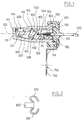
- a speed sensor designed to be placed in a wheel hub or axle bearing of motor vehicles and which comprises: a housing 100, a cap or cover 200 molded onto an output cable 300, a electric transducer 400, a three-dimensional rigid printed circuit 500 and a corner 600.
- the three-dimensional rigid printed circuit 500 carries electrical components 510.
- the latter form a circuit for processing and shaping the electrical signal from the electrical transducer 400.
- the latter is advantageously formed by a Hall effect probe or a magnetoresistance.
- the three-dimensional rigid printed circuit 500 is formed of a single piece of thermoplastic material coated locally with electrically conductive tracks.
- These electrically conductive tracks provide electrical connections between the outputs of the transducer 400 and the components 510, as well as with the conductors of the connection cable 300.
- This connection cable 300 can be multi-conductor. It can also be formed from a coaxial cable.
- a cable 300 comprising an electrically conductive inner core 302, a second conductor 303 concentric with this core and separated from it by an electrically insulating layer and an electrically conductive outer shield 304 preferably formed of a braid, itself separated from the second conductor 303 by an electrically insulating layer and covered with an electrically insulating layer.
- the core 302 and the second conductor 303 of the cable 300 are connected, preferably by soldering, to respective electrically conductive tracks of the printed circuit 500.
- the shield 304 is optionally connected to a part 700 comprising a barrel crimped on the cable 300.
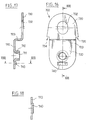
- the rigid printed circuit 300 can be the subject of numerous variant embodiments depending on the sensor considered. For this reason, its geometry will not be described in detail later. However, we will discuss later, various basic characteristics of this rigid printed circuit 500 with reference to FIGS. 11 to 15.
- the housing 100 can be the subject of numerous variant embodiments, as regards its geometry or its nature. It can be made for example of metal or based on synthetic plastic material, for example thermoplastic or thermosetting, provided that it does not disturb the physical or electrical quantity to be measured.
- This housing 100 is generally centered on an axis 102. However, it is not necessarily formed of a body of revolution. It preferably comprises an annular skirt 110 centered around the axis 102 and closed at one end by a bottom wall 112 transverse to the axis 102. At its opposite end which corresponds to the opening contour, the housing 100 is provided preferably on its outer surface, an annular collar or rib 114.
- the annular skirt 110 is provided, on its internal surface 111, in the vicinity of the bottom wall 112 and on a limited sector of its periphery, with a ramp 113 inclined with respect to the axis 102.
- the ramp 113 can be inclined on the order of 5 to 20 °, typically 10 ° relative to the axis 102.
- the aforementioned corner 600 is interposed between this ramp 113 and a face 502 of the rigid printed circuit 500.
- this face 502 of the printed circuit 500 is parallel to the axis 102.
- the corner 600 is for its part tapered towards the bottom 112 from the housing.
- the corner 600 when the corner 600 is urged to move towards the bottom 112, it itself urges the printed circuit 500 in the direction of the zone 115 of the internal surface 111 of the housing, diametrically opposite to the ramp 113.
- the electric transducer 400 being meanwhile placed on the surface 504 of the rigid printed circuit 500 opposite the face 502 adjacent to the corner 600, it is understood that the stress of the corner 600 on the circuit printed 500 tends to press the electrical transducer 400 against the aforementioned area 115 of the internal surface 111 of the housing.
- the transducer 400 is precisely positioned relative to the housing 100 and therefore relative to the environment in which the housing 100 is placed.
- a spring element 610 extending parallel to the axis 102 and interposed between the corner 600 and a recess 506 formed on the rigid printed circuit 500.
- the corner 600 and the spring 610 can be formed from parts independent of the printed circuit 500.
- the wedge 600 and the element 610 may have come from molding with the rigid printed circuit 500.
- FIG. 2 in side view, a corner 600 and two curved elastic connecting straps 610 capable of coming from molding with the rigid printed circuit 500 have been illustrated, in order to connect the latter to the corner 600.
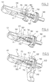
- the senor shown in FIG. 1 further comprises a part 700 provided with a barrel 710 crimped on the cable 300, preferably on the external shielding 304 of the latter.
- the part 700 is preferably made of an electrically conductive material, advantageously metal.
- this barrel 710 is secured at its outer periphery, and at one of its axial ends, a flat collar 720 centered on the axis of the barrel and transverse to this axis.
- the collar 720 has an external diameter complementary to the opening contour of the housing 100 so that the collar closes this assembly contour after assembly.
- the flange 720 itself extends, at its outer periphery, by a cylindrical skirt 722 centered on the axis of the barrel.
- This skirt 722 also has an outside diameter complementary to the opening contour of the housing 100.
- the skirt 722 is placed on the side of the flange 720 opposite the barrel 710.
- the skirt 722 can extend itself, radially, over a limited area of its circumference, by a flange 730 generally radial with respect to the 'axis of the barrel 710.
- the flange 730 preferably has an eyelet 732 for fixing.
- the procedure is preferably as follows.
- the barrel 710 of part 700 is crimped onto the shield 304 of the cable 300.
- the core 302 and the second conductor 303 of the cable 300 are fixed by welding on the respectively associated electrical tracks of the rigid printed circuit 500.
- the assembly thus formed printed circuit 500 equipped with the components 510, 400, as well as the wedge 600 and the spring 610, the part 700 and the cable 300 are positioned in the housing 100.
- the collar 720 and the skirt 722 then close the opening outline of the housing 100.
- the collar 720 prohibits any penetration of the thermoplastic overmolding material inside the cavity of the housing 100 and consequently protects the printed circuit 500, the electrical tracks thereof, the components 510 and transducer 504.
- the spring 610 pushes the corner 600 towards the bottom wall 112 which ensures that the transducer is wedged electric 400 against the zone 115 of the internal wall of the housing 100.
- the transducer 400 is thus positioned with precision.
- the overmolding of the cap 200 covers the rib 114 of the housing 100 in order to seal it tightly and ensure perfect immobilization of the part 700 and of the cable 300 relative to the housing 100.
- an injection point is provided which is directed not point directly towards the outer sheath of the cable 300, but directed towards the flange 720 of the part 700.
- the part 700 and in particular the collar 720 facilitates the positioning of the assembly in the overmolding tool and, thanks to the crimping on the cable 300 prohibits any accidental tearing of the latter.
- the part 700 thus avoids any need for sealing, in particular using an epoxy resin, as was generally used in conventional sensors.
- said part 700 comprises a flange 730 provided with an eyelet 732 generally conforming to the embodiment of FIG. 1.
- the cap 200 comprises, when molded, a cone or cylinder 210 which extends on the outside around the cable 300 to seal it.
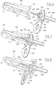
- the rigid three-dimensional printed circuit 500 shown in FIG. 9 conforms to the drawings of FIGS. 11 to 15.
- this printed circuit 500 is formed by an elongated body produced by molding plastic material, for example thermoplastic and which has a general plane of symmetry coinciding with the section plane of FIG. 12.
- This printed circuit body 500 can be the subject of numerous variants. Preferably, it comprises, at a tapered front end 510, a cradle 512 for receiving the electrical transducer 400.
- the part 500 has a channel 530 intended to receive the end of the cable 300 and which preferably comprises a cradle 532 intended to receive the electrically conductive core 302 of the cable 300, which cradle 532 is covered with an electrically conductive track, and a cradle 534 intended to receive the conductor 303 and which is also covered with an electrically conductive track respectively associated with this conductor 303.
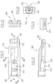
- FIGS. 16 to 18 We find in FIGS. 16 to 18, a part 700 in accordance with the illustration of FIGS. 6 to 9.
- FIGS. 16 to 18 we find a barrel 710, designed to be crimped onto the outer sheath of the cable 300 and possibly onto the shield 304 of the cable 300.
- This barrel 710 is extended on an axial end and on its outer periphery by the flat collar 720.
- This collar 720 is provided according to FIGS. 16 to 18 with a cloth 723 parallel to the axis 711 of the barrel, on a part of its periphery, and this cloth 723 is itself extended by a flange 730 provided with an eyelet 732.
- the flange 730 is perpendicular to the axis 711.
- the flange 730 has recesses 734, 735, on its sides to improve the anchoring of the overmolding constituting the cap 200.
- the flange 720 is provided with a key 740, formed for example by local punching of said flange 720.
- the key 740 can be formed for example diametrically opposite the flange 730 relative to the axis 711.
- the keying piece 740 must be complementary to a chamber 531 provided in the channel 530 of the printed circuit 500 at the rear end 520 thereof, to define a unique position between the part 700 and the circuit 500, and therefore compared to the electric transducer 400.
- the part 700 not only ensures the protection of the printed circuit 500 and of the components carried by it while preventing any penetration of thermoplastic material inside the housing 100, but can also ensuring a mechanical fixing function for the sensor thanks to the flange 730, and / or an electrical function, thanks to its connection to the shield 304 of the cable 300.
- the flange 730 can be more or less coated by the overmolding of the cap 200.
- the fixing flange bearing the reference 230 has come from molding with the cap 200.
- an electrical connection can also be provided between a mass provided on the rigid three-dimensional printed circuit 500 and the shield 304 of the cable 300, as well as therefore with the part 700.
- corner 600 can be the subject of numerous embodiments.
- FIG. 10a shows a corner 600 integral with a spring 610 in the form of a ring which is provided with a finger 612 by which the corner 600, which is formed from an independent part of the printed circuit 500, can to be engaged and maintained on the latter.
- FIG. 10b shows a variant according to which the wedge 600 is formed by corrugations coming from molding on the printed circuit 500.
- FIG. 10c shows a variant according to which the wedge 600 has come from molding on the printed circuit 500 and connected to the latter by means of elastic tabs 612.
- FIG. 10d shows a variant according to which the wedge 600 is formed by an elastic tongue molded from the printed circuit 500.
- FIG. 10e shows a variant according to which the wedge 600 is molded on the printed circuit 500 and connected to the latter by means of a curved elastic bridge 612.
- FIG. 10f shows a variant according to which the wedge 600 has come from molding on the printed circuit 500 and delimited therein by a slot 614 which receives a spring leaf 610 engaged in the printed circuit 500 and maintained on it. this.
- FIG. 10g shows a variant according to which the corner 600 has come from molding on the printed circuit 500 and delimited therein by a slot 614 which receives a leaf spring 610.
- Figure 10h There is shown in Figure 10h a variant in which the corner 600 is formed of several elastic strips 610 in the form of a comb.
- corner 600 has not been shown in FIGS. 9 and 11 to 15.
Landscapes
- Physics & Mathematics (AREA)
- General Physics & Mathematics (AREA)
- Transmission And Conversion Of Sensor Element Output (AREA)
Applications Claiming Priority (2)
| Application Number | Priority Date | Filing Date | Title |
|---|---|---|---|
| FR9409442A FR2723201B1 (fr) | 1994-07-29 | 1994-07-29 | Perfectionnement aux capteurs de grandeur physiqueet electrique, notamment aux capteurs de roulement |
| FR9409442 | 1994-07-29 |
Publications (1)
| Publication Number | Publication Date |
|---|---|
| EP0694765A1 true EP0694765A1 (de) | 1996-01-31 |
Family
ID=9465901
Family Applications (2)
| Application Number | Title | Priority Date | Filing Date |
|---|---|---|---|
| EP95401782A Withdrawn EP0694765A1 (de) | 1994-07-29 | 1995-07-27 | Herstellung von Sensoren, die physische oder elektrische Werte messen |
| EP95401783A Withdrawn EP0694766A1 (de) | 1994-07-29 | 1995-07-27 | Verfahren zur Herstellung von physische oder elektrische Werte messenden Sensoren |
Family Applications After (1)
| Application Number | Title | Priority Date | Filing Date |
|---|---|---|---|
| EP95401783A Withdrawn EP0694766A1 (de) | 1994-07-29 | 1995-07-27 | Verfahren zur Herstellung von physische oder elektrische Werte messenden Sensoren |
Country Status (2)
| Country | Link |
|---|---|
| EP (2) | EP0694765A1 (de) |
| FR (1) | FR2723201B1 (de) |
Cited By (3)
| Publication number | Priority date | Publication date | Assignee | Title |
|---|---|---|---|---|
| EP1553417A1 (de) * | 2004-01-09 | 2005-07-13 | Electricfil Automotive | Schwingungsfester Geschwindigkeitssensor |
| US7093505B2 (en) | 2002-07-17 | 2006-08-22 | The Timken Company | Speed sensor and method of attaching the same |
| CN111051821A (zh) * | 2017-08-23 | 2020-04-21 | 纬湃科技德国有限责任公司 | 传感器部件、传感器部件的预组装结构以及用于生产传感器部件的方法 |
Families Citing this family (1)
| Publication number | Priority date | Publication date | Assignee | Title |
|---|---|---|---|---|
| DE102008005315A1 (de) | 2008-01-21 | 2009-07-23 | Robert Bosch Gmbh | Verfahren und Vorrichtung zur Herstellung eines Magnetfeldsensors |
Citations (5)
| Publication number | Priority date | Publication date | Assignee | Title |
|---|---|---|---|---|
| EP0194213A1 (de) * | 1985-02-26 | 1986-09-10 | Société à Responsabilité Limitée L'ELECTRICFIL INDUSTRIE | Elektromagnetische Aufnehmer |
| EP0282967A2 (de) * | 1987-03-18 | 1988-09-21 | Sumitomo Electric Industries, Ltd. | Sensor zur Feststellung von einer Änderung im magnetischen Feld |
| DE3827937A1 (de) * | 1988-08-12 | 1990-02-15 | Siemens Ag | Elektrischer messwertaufnehmer |
| FR2683315A1 (fr) * | 1991-11-05 | 1993-05-07 | Electricfil | Capteur d'une grandeur physique comportant un corps de support et de centrage des divers composants de mesure de la grandeur physique. |
| FR2692351A1 (fr) | 1992-06-15 | 1993-12-17 | Jaeger | Capteur, notamment capteur de rotation intégré dans un roulement de véhicule automobile. |
-
1994
- 1994-07-29 FR FR9409442A patent/FR2723201B1/fr not_active Expired - Fee Related
-
1995
- 1995-07-27 EP EP95401782A patent/EP0694765A1/de not_active Withdrawn
- 1995-07-27 EP EP95401783A patent/EP0694766A1/de not_active Withdrawn
Patent Citations (5)
| Publication number | Priority date | Publication date | Assignee | Title |
|---|---|---|---|---|
| EP0194213A1 (de) * | 1985-02-26 | 1986-09-10 | Société à Responsabilité Limitée L'ELECTRICFIL INDUSTRIE | Elektromagnetische Aufnehmer |
| EP0282967A2 (de) * | 1987-03-18 | 1988-09-21 | Sumitomo Electric Industries, Ltd. | Sensor zur Feststellung von einer Änderung im magnetischen Feld |
| DE3827937A1 (de) * | 1988-08-12 | 1990-02-15 | Siemens Ag | Elektrischer messwertaufnehmer |
| FR2683315A1 (fr) * | 1991-11-05 | 1993-05-07 | Electricfil | Capteur d'une grandeur physique comportant un corps de support et de centrage des divers composants de mesure de la grandeur physique. |
| FR2692351A1 (fr) | 1992-06-15 | 1993-12-17 | Jaeger | Capteur, notamment capteur de rotation intégré dans un roulement de véhicule automobile. |
Cited By (4)
| Publication number | Priority date | Publication date | Assignee | Title |
|---|---|---|---|---|
| US7093505B2 (en) | 2002-07-17 | 2006-08-22 | The Timken Company | Speed sensor and method of attaching the same |
| EP1553417A1 (de) * | 2004-01-09 | 2005-07-13 | Electricfil Automotive | Schwingungsfester Geschwindigkeitssensor |
| CN111051821A (zh) * | 2017-08-23 | 2020-04-21 | 纬湃科技德国有限责任公司 | 传感器部件、传感器部件的预组装结构以及用于生产传感器部件的方法 |
| US11536594B2 (en) | 2017-08-23 | 2022-12-27 | Vitesco Technologies Germany Gmbh | Sensor component, pre-assembly arrangement for a sensor component, and method for producing a sensor component |
Also Published As
| Publication number | Publication date |
|---|---|
| FR2723201A1 (fr) | 1996-02-02 |
| FR2723201B1 (fr) | 1996-10-25 |
| EP0694766A1 (de) | 1996-01-31 |
Similar Documents
| Publication | Publication Date | Title |
|---|---|---|
| WO2002056388A2 (fr) | Boîtier semi-conducteur a capteur, muni d'un insert, et son procede de fabrication | |
| EP0520853A1 (de) | Dichtungsanordnung für einen an ein abgedichtetes Walzlager angepassten Messwertaufnehmer | |
| FR2631664A1 (fr) | Montage de moyeu de roue non motrice de vehicule equipe d'un dispositif a pulseur et capteur pour mesure de la vitesse de rotation de la roue | |
| FR3006851A1 (fr) | Appareil de controle electronique pour vehicule avec etancheite de logement de type etanche a l'eau et methode de fabrication associee | |
| EP1431596B1 (de) | Selbstverriegelnde Verbindung zwischen einer Kugelkopf Stange und einem flachen Teil | |
| FR2661373A1 (fr) | Detecteur de pression de pneumatiques. | |
| EP2546614B1 (de) | Sensor- oder Detektorvorrichtung mit einem perfektionierten Kabelführungsstöpsel | |
| FR2675860A1 (fr) | Roulement comprenant un capteur de vitesse. | |
| FR2690989A1 (fr) | Codeur annulaire composite. | |
| EP0694765A1 (de) | Herstellung von Sensoren, die physische oder elektrische Werte messen | |
| FR2723200A1 (fr) | Procede de fabrication de capteurs de grandeur physique et electrique | |
| FR3059202B1 (fr) | Procede de fabrication sur une plaque de maintien d'un module electronique avec des formes de positionnement depassant du surmoulage final | |
| EP0480844B1 (de) | Verbesserungen an vergossenen Messaufnehmern, insbesondere an Geschwindigkeitsmessaufnehmern für Kraftfahrzeuge | |
| EP0242297B1 (de) | Aktiver Organträgerzusammenbau auf einer Kraftfahrzeugradfelge, Dichtung und aktive Organträger für diesen Zusammenbau | |
| FR3067515A1 (fr) | Interrupteur, en particulier pour le levier de la pedale de frein d'un vehicule | |
| FR2686690A1 (fr) | Systeme de capteur comprenant un plongeur destine a etre place dans l'alesage d'un support. | |
| EP1638789B1 (de) | Elektrische verbindungsvorrichtung zwischen einem rad und einer kugellager-nabeanordnung | |
| EP0461992B1 (de) | Messaufnehmer, insbesondere Geschwindigkeitsmessaufnehmer für Kraftfahrzeuge | |
| FR3045751A1 (fr) | Etrier de frein equipe d'une plaque protectrice montee au moyen de deux pions de blocage | |
| WO2019077255A1 (fr) | Valve de gonflage pour jante de pneu avec limitation de déformation élastique | |
| FR2662503A1 (fr) | Capteur electrique de vitesse pour vehicules automobiles. | |
| EP0519816B1 (de) | Verbesserungen einer Kupplungsvorrichtung, insbesondere zum Gebrauch bei Geschwindigkeitssensoren | |
| FR3076609A1 (fr) | Capteur angulaire | |
| EP0519817A1 (de) | Trägervorrichtung für die Kapsel eines elektrischen Wandlers | |
| FR2716702A1 (fr) | Système de détection d'usure de garniture de friction de frein à disque ou à tambour. |
Legal Events
| Date | Code | Title | Description |
|---|---|---|---|
| PUAI | Public reference made under article 153(3) epc to a published international application that has entered the european phase |
Free format text: ORIGINAL CODE: 0009012 |
|
| AK | Designated contracting states |
Kind code of ref document: A1 Designated state(s): AT DE ES GB IT |
|
| 17P | Request for examination filed |
Effective date: 19960722 |
|
| 17Q | First examination report despatched |
Effective date: 19980212 |
|
| STAA | Information on the status of an ep patent application or granted ep patent |
Free format text: STATUS: THE APPLICATION IS DEEMED TO BE WITHDRAWN |
|
| 18D | Application deemed to be withdrawn |
Effective date: 19990710 |