EP0694823A2 - Montre électronique analogique - Google Patents
Montre électronique analogique Download PDFInfo
- Publication number
- EP0694823A2 EP0694823A2 EP95305231A EP95305231A EP0694823A2 EP 0694823 A2 EP0694823 A2 EP 0694823A2 EP 95305231 A EP95305231 A EP 95305231A EP 95305231 A EP95305231 A EP 95305231A EP 0694823 A2 EP0694823 A2 EP 0694823A2
- Authority
- EP
- European Patent Office
- Prior art keywords
- signal
- circuit
- information
- time
- timepiece
- Prior art date
- Legal status (The legal status is an assumption and is not a legal conclusion. Google has not performed a legal analysis and makes no representation as to the accuracy of the status listed.)
- Withdrawn
Links
- 230000008859 change Effects 0.000 claims abstract description 127
- 230000033001 locomotion Effects 0.000 claims abstract description 53
- 230000005236 sound signal Effects 0.000 claims abstract description 27
- 230000004044 response Effects 0.000 claims abstract description 17
- 230000007274 generation of a signal involved in cell-cell signaling Effects 0.000 claims abstract description 3
- 210000004247 hand Anatomy 0.000 description 71
- 238000000034 method Methods 0.000 description 16
- 230000010355 oscillation Effects 0.000 description 16
- 238000010586 diagram Methods 0.000 description 9
- 238000004519 manufacturing process Methods 0.000 description 2
- 230000007246 mechanism Effects 0.000 description 2
- 230000001360 synchronised effect Effects 0.000 description 2
- 230000000007 visual effect Effects 0.000 description 2
- 230000008901 benefit Effects 0.000 description 1
- 238000012986 modification Methods 0.000 description 1
- 230000004048 modification Effects 0.000 description 1
- 230000008569 process Effects 0.000 description 1
- 210000000707 wrist Anatomy 0.000 description 1
Images





Classifications
-
- G—PHYSICS
- G04—HOROLOGY
- G04B—MECHANICALLY-DRIVEN CLOCKS OR WATCHES; MECHANICAL PARTS OF CLOCKS OR WATCHES IN GENERAL; TIME PIECES USING THE POSITION OF THE SUN, MOON OR STARS
- G04B45/00—Time pieces of which the indicating means or cases provoke special effects, e.g. aesthetic effects
- G04B45/0038—Figures or parts thereof moved by the clockwork
- G04B45/0061—Moving parts of the clockwork, e.g. pendulum, hands in special form, mostly constructed as a figure
-
- G—PHYSICS
- G04—HOROLOGY
- G04C—ELECTROMECHANICAL CLOCKS OR WATCHES
- G04C21/00—Producing acoustic time signals by electrical means
-
- G—PHYSICS
- G04—HOROLOGY
- G04C—ELECTROMECHANICAL CLOCKS OR WATCHES
- G04C3/00—Electromechanical clocks or watches independent of other time-pieces and in which the movement is maintained by electric means
- G04C3/14—Electromechanical clocks or watches independent of other time-pieces and in which the movement is maintained by electric means incorporating a stepping motor
Definitions
- This invention relates to an analog electronic timepiece which uses hands as a means for indicating time.
- a method of generating a shot sound and a method of generating a sound or of outputting a melody sound in interlocking relation to the motion of a marionette are known.
- a melody clock has also been known which is designed to drive the hands in synchronism with the scale of a melody by a key input signal or a coincidence input signal corresponding to an alarm setting time so that the hands may point to a position on a pictorial design of a score or keyboard provided in a predetermined position on the timepiece face (Japanese unexamined patent publication (Kokai) No. S59-63585(1984)).
- the informing of time by a marionette clock is accompanied by complexity of the mechanism of the timepiece, posing the problem that the timepiece has become difficult to miniaturize.
- an analog electronic timepiece comprising: hands for indicating time; means for driving the hands; means for providing a predetermined frequency signal and counting time information in response thereto; time information signal generating means for forwarding time information to the hands driving means in response to counted time information; characterised in that the timepiece further comprises: judgement means for producing a hand start signal in response to the finding of a predetermined condition; information operation storing means for storing and providing information pertaining to hand movement operations for various conditions; and information signal generating means for forwarding a timing signal and an operation generation signal to the hands driving means in response to a hand start signal and in accordance with the information provided by the information operation storing means for the found predetermined condition.
- the timepiece may also comprise sound signal generating means for forwarding a sound generating signal to a sound generating means.
- the judgement means such of such a timepiece may be arranged to produce a sound generation start signal in response to the finding of a predetermined condition
- the information operation storing means may be arranged to store and provide information pertaining to the generation of sound for various conditions
- the information signal generating means may be arranged to forward a timing signal and an operation generation signal to the sound signal generation means in response to a sound generation start signal and in accordance with the information provided by the information operation storing means for the found predetermined condition.
- the condition may be, for example, time coincidence or mode change.
- the judgement means is a time coincidence circuit for producing a start signal of a time coincidence operation when the counted time information coincides with a preset time
- the information operation storing means is a time coincidence operation storing circuit for storing and providing information pertaining to operations for various time coincidences
- the information signal generating means is a time coincidence signal generating circuit for producing a timing signal and a time coincidence operation signal.
- the judgement means is a mode change circuit for producing a start signal of a mode change operation when a mode change signal is produced by a mode change key
- the information operation signal storing means is a mode change operation storing circuit for storing and providing information pertaining to operations for various mode changes
- the information signal generating means is a mode change signal generating circuit for producing a timing signal and a mode change operation signal.
- the timepiece may, of course, be visually indicative of both time coincidence and mode change.
- such a timepiece may also comprise an operation selection means for selecting which of the time coincidence operation and mode change operation is to be preferentially executed.
- the time coincidence circuit may be arranged to perform a judgement of time coincidence only when the timepiece in a predetermined mode. This reduces power consumption of the timepiece.
- the hands driving means may comprise a single motor in the motor driving circuit. This simplifies the structure of the timepiece and current consumption is reduced.
- the hands driving means may comprise two motors in the motor driving circuit.
- one motor may be provided to drive an hour hand and the other motor provided to drive a minute hand.
- another option is that one motor is provided to drive the hour and minute hand, and the other motor is provided to drive a second hand.
- the use of two or more motors and motor driving circuits enables dynamic hand movement operation and high degree of motion to be obtained.
- an analog electronic timepiece comprising at least two hands for indicating time; at least one motor for driving the hands; at least one motor driving circuit for driving the motor; a mode change key for manually inputting a mode of the timepiece, and outing a mode change signal; a sound signal generating circuit for outputting a sound generating signal to a speaker to generate a sound; an oscillation circuit for oscillating and outputting a standard signal; a frequency dividing circuit for frequency dividing the standard signal output from the oscillation circuit into predetermined frequency signals; a clock circuit for counting time information in response to the predetermined frequency signals output from the frequency dividing circuit; and a time information signal generating circuit for outputting an operation signal for informing the time information to the motor driving circuit and sound signal generating circuit in response to the time information counted by the clock circuit; characterized in that there is also provided a judgement circuit for judging a predetermined condition of the timepiece to output a starting signal of hand movement and generation of sound; an information operation storing circuit
- the judgement circuit may comprise a time coincidence circuit for judging that the time information caused by the clock circuit has coincided with a preset time, and for outputting a starting signal of the time coincidence operation
- the information operation storing circuit may comprise a time coincidence operation storing circuit for storing and reading out preselected numbers and frequencies for a time coincidence operation
- the information signal generating circuit may comprise a time coincidence signal generating circuit for producing timing signals, and outputting a time coincidence operation signal.
- the judgement circuit may comprise a mode change circuit for judging that the mode change signal has output from said mode change key and outputting a starting signal of a mode change operation
- the information operation storing circuit may comprise a mode change operation storing circuit for storing and reading out preselected numbers and frequencies for a mode change operation
- the information signal generating circuit may comprise a mode change signal generating circuit for producing timing signals, and outputting a mode change operation signal.
- the judgement circuit may comprise a time coincidence circuit for judging that the time information caused by the clock circuit has coincided with a preset time and for outputting a starting signal of a time coincidence operation and a mode change circuit for judging that the mode change signal has output from the said mode change key and for outputting the starting signal of the mode operation
- the information operation storing circuit may comprise a time coincidence operation storing circuit for storing and reading out preselected numbers and frequencies for a time coincidence operation and a mode change operation storing circuit for storing and reading out preselected numbers and frequencies for a mode change operation
- the information signal generating circuit may comprise a time coincidence signal generating circuit for producing timing signals and for outputting a time coincidence operation signal, and a mode change signal generating circuit for producing timing signals and for outputting the mode change operation signal.
- the latter timepiece may further comprise an operation selection circuit into which is input the time coincidence operation signal output from the time coincidence signal generating circuit and the mode change operation signal output from the mode change signal generating circuit.
- the operation selection circuit judges which operation is to be preferentially executed and outputs an operation generating signal to the motor driving circuit and/or the sound signal generating circuit.
- the timepiece may, for example, comprise a single or two motors and motor driving circuits.
- a timepiece which visually indicates time coincidence may be arranged such that the timepiece coincidence circuit performs judgement of time coincidence only at a predetermined mode.
- the judgement circuit judges a predetermined condition of the timepiece, the judgement circuit outputs the starting signal of the hand movement and sound generation.
- the information signal generation circuit produces timing signals for driving the hands and generating sound in response to the starting signal.
- the information signal generating circuit outputs the operation generation signal to the motor driving circuit and/or the sound signal generating circuit according to the preselected numbers of hand movement operation steps and frequencies of sound generation read out from the information operation storing circuit.
- the analog electronic timepiece according to the present invention can inform the predetermined condition of the timepiece not only audibly by sound but also, or alternatively, visually by hands movement.
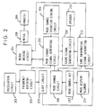
- the judgement circuit is a time coincidence circuit 104 for judging that the time information caused by said clock circuit 103 has coincided with a preset time, and for outputting a starting signal of a time coincidence operation.
- the information operation storing circuit is a time coincidence operation storing circuit 106 for storing and reading out preselected numbers and frequencies for a time coincidence operation.
- the information signal generating circuit is a time coincidence signal generating circuit 105 for producing timing signals, and outputting a time coincidence operation signal.
- an oscillation circuit 101 oscillates a standard signal and outputs to a frequency dividing circuit 102.
- the frequency dividing circuit 102 frequency divides the output signal from the oscillation circuit 101 and outputs a predetermined frequency signal.
- a clock circuit 103 inputs the frequency signal output from the frequency dividing circuit 102 and counts time information.
- a time information signal generating circuit 112 inputs the time information counted by the clock circuit 103 and outputs an operation signal for informing time information to a motor driving circuit 107 or sound signal generating circuit 110.
- a time coincidence circuit 104 judges whether the time information counted by the clock circuit 103 has coincided with a predetermined plurality of times and outputs a starting signal of hand movement and sound generation to be time coincidence signal generating circuit 105.
- a time coincidence operation storing circuit 106 previously stores, and enables reading out of, the number of hand movement operation steps of the hands 109 and the number of times of sound generation.
- the time coincidence signal generating circuit 105 Upon input of a signal for starting movement of the hands 109 and generating of sound which is output from the time coincidence circuit 104, the time coincidence signal generating circuit 105 produces timings for the movement of the hands 109 and the generation of the sound by means of the frequency signal produced by the frequency dividing circuit 102, performs judgement as to whether the hands 109 are to be driven or the sound is to be generated according to a predetermined timing stored in the time coincidence operation storing circuit 106, then outputs an operation signal to either the motor driving circuit 107 or sound signal generating circuit 110.
- the motor driving circuit 107 inputs a hand driving operation signal output from the time coincidence signal generating circuit 105 and outputs a signal for driving the hands 109 to a motor 108.
- the hands 109 indicate time information or function information pertaining to the timepiece.
- the motor 108 inputs the hand driving signal from the motor driving circuit 107 and drives the hands 109.
- the sound signal generating circuit 110 inputs a sound generation signal output from the time coincidence signal generating circuit 105 to generate sound by outputting a sound generating signal to a speaker 111.
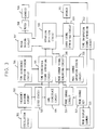
- the judgement circuit is a mode change circuit 204 for judging whether the mode change signal has output from the mode change key 213, and outputting a starting signal of a mode change operation.
- the information operation storing circuit is a mode change operation storing circuit 206 for storing and reading out preselected numbers and frequencies for a mode change operation.
- the information signal generating circuit is a mode change signal generating circuit 205 for producing timing signals, and outputting a mode change operation signal.
- an oscillation circuit 201 oscillates a standard signal and outputs to a frequency dividing circuit 202.
- the frequency dividing circuit 202 inputs the output signal from the oscillation circuit 201 to frequency divide it and outputs a predetermined frequency signal.
- a clock circuit 203 inputs a frequency signal output from the frequency dividing circuit 202 and counts time information.
- a time information signal generating circuit 212 inputs time information from the clock circuit 203 and mode information of the timepiece from a mode change circuit 204, and outputs an operation signal for informing time information or function information pertaining to the timepiece to a motor driving circuit 207 or sound signal generating circuit 210.
- a mode change key 213 inputs the mode of the timepiece.
- a mode display element 214 displays mode information input from the mode change key 213.
- a mode change circuit 204 outputs to the time information signal generating circuit 212 the mode information signal input from the mode change key 213 and outputs to a mode change signal generating circuit 205 a starting signal of a mode change operation by hand movement and sound generation.
- a mode change operation storing circuit 206 previously stores, and enables reading out of, the number of hand movement operation steps of the hands 209 and the number of times of sound generation.
- the mode change signal generating circuit 205 Upon input of the starting signal for hand movement and sound generation which is output from the mode change circuit 204, the mode change signal generating circuit 205 prepares timings for the driving of the hands 209 and for generating the sound by means of the frequency signal produced by the frequency dividing circuit 202, performs judgement as to whether the hands 209 are to be driven or the sound is to be generated according to a predetermined timing stored in the mode change operation storing circuit 206, and outputs an operation signal to the motor driving circuit 207 or sound signal generating circuit 210.
- the motor driving circuit 207 inputs a hand driving operation signal output from the mode change signal generating circuit 205 and outputs a signal for driving the hands 209 to a motor 208.
- the hands 209 indicate time information or function information pertaining to the timepiece.
- the motor 208 inputs a hand driving signal from the motor driving circuit 207 and drives the hands 209.
- the sound signal generating circuit 210 inputs a sound generation signal output from the time coincidence signal generating circuit 205 to generate the sound by outputting a sound generating signal to a speaker 211.
- the third example is a combination of the above described the first example and the second example.
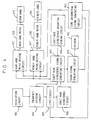
- the judgement circuit comprises a time coincidence circuit 304 for judging whether the time information caused by said clock circuit 303 has coincided with a preset time and for outputting a starting signal of a time coincidence operation, and a mode change circuit 314 for judging whether the mode change signal has output from said mode change key 313 and for outputting a starting signal of a mode change operation.
- the information operation storing circuit comprises a time coincidence operation storing circuit 306 for storing and reading out preselected numbers and frequencies for a time coincidence operation, and a mode change operation storing circuit 321 for storing and reading out preselected numbers and frequencies for a mode change operation.
- the information signal generating circuit comprises a time coincidence signal generating circuit 305 for producing timing signals and for outputting a time coincidence operation signal, and a mode change signal generating circuit 316 for producing timing signals and for outputting a mode change operation signal.
- the third example includes an operation selection circuit 320, into which is input the time coincidence operation signal output from the time coincidence signal generating circuit 305, and input the mode change operation signal output from the mode change signal generating circuit 316, for judging which operation is to be preferentially executed, and for outputting an operation generating signal to the motor driving circuit 307 and/or the sound signal generating circuit 310.
- an oscillation circuit 301 oscillates a standard signal and outputs to a frequency dividing circuit 302.
- the frequency dividing circuit 302 inputs the output signal from the oscillation circuit 301 to frequency divide it and outputs a predetermined frequency signal.
- a clock circuit 303 inputs the frequency signal output from the frequency dividing circuit 302 and counts time information.
- a time information signal generating circuit 312 inputs time information counted by the clock circuit 303 and outputs an operation signal for informing time information to a motor driving circuit 307 or sound signal generating circuit 310.
- a time coincidence circuit 304 judges whether the time information counted by the clock circuit 303 has coincided with a desired one of a plurality of preset times and outputs a starting signal of hand movement and sound generation to a time coincidence signal generating circuit 305.
- a time coincidence operation storing circuit 306 previously stores, and reads out of, the number of hand movement operation steps of the hands 309 and the number of times of sound generation of the sound.
- the time information signal generating circuit 312 inputs time information from the clock circuit 303 and mode information of the timepiece from a mode change circuit 314 and outputs an operation signal for informing time information or function information pertaining to the timepiece to the motor driving circuit 303 or sound signal generating circuit 310.
- the time coincidence signal generating circuit 305 Upon input of the starting signal of hand movement and sound generation which is output from the time coincidence circuit 304, the time coincidence signal generating circuit 305 produces timings for the driving of the hands 309 and the generating of the sound by means of a frequency signal produced by the frequency dividing circuit 302, performs judgement as to whether the hands 309 are to be driven or the sound is to be generated according to a predetermined timing stored in the time coincidence operation storing circuit 306, and outputs a time coincidence operation signal to an operation selection circuit 320.
- a mode change key 313 inputs a mode of the timepiece.
- a mode display element 315 displays mode information input from the mode change key 313.
- a mode change circuit 314 outputs the mode information signal to the time information signal generating circuit 312 input from the mode change key 313, and outputs a starting signal of a mode change operation by hand movement and sound generation to a mode change signal generating circuit 316.
- a mode change operation storing circuit 321 previously stores, and enables reading out of, the number of hand movement operation steps of the hands 309 and the number of times of sound generation of the sound.
- the mode change signal generating circuit 316 Upon input of the starting signal of hand movement and sound generation which is output from the mode change circuit 314, the mode change signal generating circuit 316 produces timings for driving of the hands 309 and for generating the sound according to the frequency signal produced by the frequency dividing circuit 302, performs judgement as to whether the hands 309 are to be driven or the sound is to be generated according to a predetermined timing stored in the mode change operation storing circuit 321, and outputs a mode change operation signal to an operation selection circuit 320.
- the operation selection circuit 320 inputs the mode change operation signal output from the mode change signal generating circuit 316 and the time coincidence operation signal output from the time coincidence signal generating circuit 305 and judges which operation is to be preferentially executed, outputting an operation signal to each of a plurality of motor driving circuits such as the motor 1 driving circuit 307 and a motor 2 driving circuit 317, or to the sound signal generating circuit 310.
- the motor driving circuit 307 inputs a hand driving operation signal output from the mode change signal generating circuit 316 and outputs a signal for driving the hands 309 to a motor 308.
- the motor driving circuit 307 inputs a hand driving operation signal output from the operation selection circuit 320 and outputs a signal for driving the hands 309 to the motor 308.
- the hands 309 indicate time information or function information pertaining to the timepiece.
- the motor 308 inputs a hand driving signal from the motor driving circuit 307 and drives the hands 309.
- the sound signal generating circuit 310 inputs a sound generation signal output from the operation selection circuit 320 to generate the sound by outputting a sound generating signal to a speaker 311.
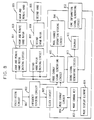
- Fig. 4 is a function block diagram of a first embodiment of the present invention.
- An oscillation circuit 401 oscillates at an oscillation frequency of 32768 Hz by application thereto of a predetermined voltage of 1.57 V.
- a frequency dividing circuit 402 frequency divides the oscillation frequency outputted from the oscillation circuit 401 into arbitrary frequencies of 1 Hz, 8 Hz, 16 Hz, and 32 Hz.
- a clock circuit 403 counts seconds of time using an arbitrary frequency of for example 1 Hz produced by the frequency dividing circuit 402, and counts the numeric value of minute digit and hour digit of time by consecutively adding one to the second digit.
- a time information signal generating circuit 412 inputs time information counted by the clock circuit 403, and outputs a hand driving operation signal to a minute hand motor driving circuit 407 every twelve seconds and to an hour hand motor driving circuit 417 every three minutes.
- a sound generation signal to a sound signal generating circuit 410.
- the hand driving cycle and output conditions for sound can be arbitrarily set.
- an exact hour coincidence circuit 404 When the time information counted by the clock circuit 403 is an exact hour such as for example 8:00:00, an exact hour coincidence circuit 404 outputs a starting signal for an exact hour coincidence operation to an exact hour coincidence signal generating circuit 405. Note that the outputting of the operation starting signal is not limited to coincidence with an exact hour, but may be at a time coinciding with a plurality of predetermined times, such as a time of exactly 30 minutes, a time of exactly 10 minutes, or a time of exactly 5 minutes.
- An exact hour coincidence operation storing circuit 406 stores operational sequences and the number of operation steps for the hands and sound at times of exact hour coincidence.
- the exact hour coincidence signal generating circuit 405 Upon input of a starting signal of an exact hour coincidence operation from the exact hour coincidence circuit 404, the exact hour coincidence signal generating circuit 405 inputs an operational sequence and number of operation steps of the hands and the sound at the time of exact hour coincidence from the exact hour coincidence operation storing circuit 406. Then the exact hour coincidence signal generating circuit 405 outputs a hand driving operation generating signal to an hour hand motor driving circuit 417 and minute hand motor driving circuit 407, and a sound output operation generation signal to a sound signal generating circuit 410 at timings synchronized with the frequency signal produced by the frequency dividing circuit 402, to control hand movement and sound generation.
- the sound signal generating circuit 410 Upon input of a sound generation signal from each of the exact hour coincidence signal generating circuit 405 and a time information signal generating circuit 412, the sound signal generating circuit 410 outputs a sound generating signal to a speaker 411 to generate a sound.
- the hour hand motor driving circuit 417 drives the hour hand 419 through the hour hand motor 418.
- the minute hand motor driving circuit 407 drives the minute hand 409 through the minute hand motor 408.
- two hand driving motors and two hand driving motor driving circuits each are provided, as a result of which the hour hand and the minute hand can be driven simultaneously in their respectively separate motions. It is possible to realize more dynamic hand movement operation and a higher degree of motion than with only one between them.
- One example is the case in which manual hands obtained by printing a pictorial design of characters on the face of the timepiece and designing the tip of the hour and minute hands into a hand shape are used. It is possible to simultaneously move the two hands differently, realizing more real motions such as, for example, waving or clapping both hands, etc.
- a single motor for driving the hands and hand driving motor driving circuit for hand movement operation can be provided for both hands.
- Fig. 5 is a front view of a timepiece which performs the exact hour coincidence operation of the first embodiment.
- Fig. 6 is a view showing an example of the operational sequence of the exact hour coincidence operation of the first embodiment.
- Fig. 7 is a hand movement operational step table showing an example of operational steps for the exact hour coincidence operation of the first embodiment.
- the timepiece has an hour hand 501 and a minute hand 502 for indicating time.
- These hands 501, 502 are driven by their respectively separate motors and motor driving circuits.
- the minute hand 502 is driven at 300 steps per one round while the hour hand 501 is driven at 240 steps per one round in a time display state.
- the timepiece is also provided with a crown switch 503.
- This switch can be manually operated to change the mode, for example, between one mode in which time coincidence is judged and one in which it is not.
- a visual indication of the time coincidence is provided and in the latter it is not.
- this enables power consumption of the timepiece to be reduced when the user does not require the visual indication.
- Figs. 6 and 7 when the timepiece shows exactly 8:00 (hand movement step 600), the minute hand 502 is driven clockwise every 25 steps until it overlaps the hour hand 501. At this time, every 25 steps of the minute hand 502 driven, an envelope-equipped buzzer sound (hereinafter called "envelope sound") of 718.75 msec is generated eight times as a chime. Thereby, the exact hour is informed by the number of the envelope sound and the steps of the minute hand 502 (hand movement step 601). In this case, repetition number "H" in Fig. 7 is eight.
- envelope sound envelope-equipped buzzer sound
- the hour hand 501 is driven counterclockwise and the minute hand 502 clockwise in 10 steps each centering on the position where both hands overlap, in such a manner that each of the hands swings about that position. At this time, each time the hands overlap each other, the envelope sound is generated (hand movement step 602).
- the minute hand 502 and the hour hand 501 are each driven clockwise to the 10-minute position and to the 10 o'clock position (hand movement step 603).
- the minute hand 502 is driven counterclockwise from the 10-minute position and the hour hand 501 is driven clockwise from the 10 o'clock position, so that they swing in 20 steps each. At this time, each time the drive directions of the hands are altered, a buzzer sound of 31.25 msec is generated (hand movement step 604).
- the minute hand 502 and the hour hand 501 are each driven clockwise from the 10-minute position and the 10 o'clock position to the present-time position (hand movement step 605). At this time, the hands correct the difference of the exact hour coincidence operation starting time from the present time.
- the hands driven by the two motors and two motor driving circuits were a combination of the hour hand 501 and the minute hand 502
- the types of hands driven can also be arbitrarily set in such a manner that one set of motor and motor driving circuit drives the hour and minute hands in interlocking relation with each other, while the other set of a motor and a motor driving circuit drives the second hand.
- the three hands - hour hand, minute hand, and second hand - can each also be separately moved.
- Fig. 8 is a functional block diagram showing a second embodiment of the present invention.
- An oscillation circuit 801 oscillates at an oscillation frequency of 32768 Hz by application thereto of a predetermined voltage of 1.57 V.
- a frequency dividing circuit 802 frequency divides the oscillation frequency output from the oscillation circuit 401 to arbitrary frequencies of 1 Hz, 8 Hz, 16 Hz, and 32 Hz.
- a clock circuit 803 counts seconds by using a given frequency of for example 1 Hz produced by the frequency dividing circuit 802, and counts minute digits and hour digits by consecutively adding these second digits.
- a time information signal generating circuit 812 inputs time information counted by the clock circuit 803, and outputs a hand driving operation signal to a second hand motor driving circuit 807 every second and to an hour and minute hand motor driving circuit 817 every ten seconds. Further, at times of coincidence with an alarm set time or key operation, the circuit 812 outputs a sound generation signal to a sound signal generating circuit 810. Note that the hand driving cycle and sound generating conditions can be arbitrarily set.
- a mode change key 813 generates a mode change signal by a manual operation and outputs information thereof to a mode display element 814 and a mode change circuit 804.
- a mode change key may be a button switch, crown switch, etc.
- the mode display element 814 displays the mode information output from the mode change key 813.
- a mode change circuit 804 inputs the mode change signal output from the mode change key 813, and outputs mode information to the time information signal generating circuit 812 and a starting signal of a mode change operation to a mode change signal generating circuit 805.
- a mode change operation storing circuit 806 stores operational sequences and the number of operation steps of the hands and the sound at times of mode change.
- the mode change signal generating circuit 805 Upon input of the mode change operation starting signal from the mode change circuit 804, the mode change signal generating circuit 805 inputs the operational sequence and number of operation steps for the hands and sound at the time of mode change from the mode change operation storing circuit 806. Then the mode change signal generating circuit 805 outputs a hand driving operation signal to an hour and minute motor driving circuit 817 and a second hand motor driving circuit 807, and a sound generation signal to the sound signal generating circuit 810 at timings synchronized with a frequency signal produced by the frequency dividing circuit 802, to control hand movement and sound generation.
- the sound signal generating circuit 810 Upon input of sound generation signals from the mode change signal generating circuit 805 and the time information signal generating circuit 812, the sound signal generating circuit 810 outputs a sound generating signal to a speaker 811 to generate a sound.
- the hour and minute hands motor driving circuit 817 drives the hour and minute hands 819 through an hour and minute hands motor 818.
- the second hand motor driving circuit 807 drives the second hand 809 through a second hand motor 808.
- one motor and motor driving circuit for driving all the hands can be provided.
- current consumption can be suppressed to less than in the case of using a plurality of motors.
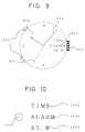
- Fig. 9 is a front view of a timepiece wherein a mode change operation of the second embodiment is performed.
- Fig. 10 shows a mode display portion on a dial of the timepiece wherein the mode change operation of the second embodiment is performed.
- the mode print on the mode display portion 900 is such that a TIME mode print 1001 is colored red, ALARM mode print 1000 is colored green, and ST.W mode print 1002 is colored blue.
- a mode display window 1003 is so formed that the present mode state can be judged by comparing the color visible from the mode display window with each mode print color.
- Fig. 11 shows an example of the operational sequence for the mode change operation according to the second embodiment.
- the timepiece has three modes and the mode display portion 900 for displaying such modes on the face.
- a second hand 901 and a set of an hour hand 902 and minute hand 903 for indicating time are driven respectively by separate motors and separate motor driving circuits.
- the second hand 901 is driven at 60 steps per one round, and the hour hand 902 is driven at 4320 steps per one round interlocking with a minute hand 903 in the time display mode.
- the second hand 901 After the second hand 901 indicates the new mode for three seconds, the second hand 901 is driven clockwise and then restored to a time indicating state (hand movement step 1102).
- the hand movement step 1102 as a method by which the second hand 901 is restored to the time display mode, there is a method by which the second hand 901 is restored counterclockwise, a method by which the second hand 901 is driven in the direction in which the hand driving time length is shortest, a method by which the second hand 901 is kept still until the present time coincides with the indicated time on the mode print portion 900, etc., these methods being able to be arbitrarily set.
- the time length during which the second hand 901 is indicating a relevant mode is not limited to three seconds but may be arbitrarily set.
- the position of the mode display portion 900 is not limited to the 3 o'clock position on the dial but may be arbitrarily set to, for example, a 12 o'clock position, 6 o'clock position, 9 o'clock position, etc. Further, the method by which the mode is displayed is not limited to the mode display window but may also be a method which uses a mode display hand.
- the hands driven by the two motors and two motor driving circuits are a combination of the hour and minute hands 819 and the second hand 809
- the types of hands driven can also be arbitrarily set in such a manner that one set of a motor and motor driving circuit drives the hour hand and another set of a motor and motor driving circuit drives the minute hand, as in the case of the operation described in the first embodiment.
- the three hands of hour hand, minute hand, and second hand can also be separately moved.
- Fig. 12 is a functional block diagram of a third embodiment of the present invention.
- the hour coincidence informing function according to the first embodiment and the mode change informing function according to the second embodiment are both incorporated into one timepiece.
- an operation selection circuit 2020 inputs an exact hour coincidence signal output from an exact hour coincidence signal generating circuit 2005 at an exact hour coincidence time and a mode change operation signal output from a mode change signal generating circuit 2016.
- the operation selection circuit 2020 performs judgement as to which operation is preferentially executed.
- the exact hour coincidence operation is interrupted at that time and the mode change operation is performed instead.
- the mode change operation is interrupted at that time and the exact hour coincidence operation is performed instead. Namely, the operation signal output later is executed with priority.
- the exact hour coincidence operation is executed first and after completion thereof the mode change operation is executed.
- time information is performed when exact hour coincidence has been obtained
- the time informing operation is not limited to a time corresponding to an exact hour, but may be performed at a time corresponding to a plurality of preset times, such as a time of exactly 30 minutes, a time of exactly 10 minutes, or a time of exactly 5 minutes.
- the present invention provides an advantageous analog electronic timepiece having a function by use of which a plurality of predetermined times as well as a mode change can be visually informed so that they are easily understood by hand movement and sound generation.
- the electronic timepiece can be produced without complicating the function even for a small timepiece such as a wrist watch.
Landscapes
- Physics & Mathematics (AREA)
- General Physics & Mathematics (AREA)
- Electromechanical Clocks (AREA)
- Electric Clocks (AREA)
Applications Claiming Priority (2)
| Application Number | Priority Date | Filing Date | Title |
|---|---|---|---|
| JP174544/94 | 1994-07-26 | ||
| JP06174544A JP3142719B2 (ja) | 1994-07-26 | 1994-07-26 | アナログ電子時計 |
Publications (2)
| Publication Number | Publication Date |
|---|---|
| EP0694823A2 true EP0694823A2 (fr) | 1996-01-31 |
| EP0694823A3 EP0694823A3 (fr) | 1999-01-20 |
Family
ID=15980409
Family Applications (1)
| Application Number | Title | Priority Date | Filing Date |
|---|---|---|---|
| EP95305231A Withdrawn EP0694823A3 (fr) | 1994-07-26 | 1995-07-26 | Montre électronique analogique |
Country Status (3)
| Country | Link |
|---|---|
| US (1) | US5619478A (fr) |
| EP (1) | EP0694823A3 (fr) |
| JP (1) | JP3142719B2 (fr) |
Cited By (1)
| Publication number | Priority date | Publication date | Assignee | Title |
|---|---|---|---|---|
| EP1491974A1 (fr) * | 2003-06-25 | 2004-12-29 | The Swatch Group Management Services AG | Pièce d'horlogerie ayant un affichage analogique agencé pour montrer une animation |
Families Citing this family (12)
| Publication number | Priority date | Publication date | Assignee | Title |
|---|---|---|---|---|
| WO1992018916A1 (fr) * | 1991-04-16 | 1992-10-29 | Citizen Watch Co., Ltd. | Montre electronique avec fonction de mesure |
| US6556514B2 (en) * | 2001-08-15 | 2003-04-29 | Products Of Tomorrow, Inc. | Combination clock and art set apparatus |
| US6975562B2 (en) * | 2003-12-05 | 2005-12-13 | Timex Group B.V. | Wearable electronic device with mode operation indicator |
| US7466632B1 (en) * | 2004-05-04 | 2008-12-16 | Westerngeco L.L.C. | Method and apparatus for positioning a center of a seismic source |
| US20060018201A1 (en) * | 2004-07-20 | 2006-01-26 | Lizzi Ronald S | Method of and device for setting and indicating a plurality of alerts using an indicator hand |
| US7258481B2 (en) * | 2004-12-22 | 2007-08-21 | Timex Group B.V. | Multiindicator device and method for calibrating/setting same |
| CN105135238A (zh) | 2008-11-19 | 2015-12-09 | 罗姆股份有限公司 | Led照明装置 |
| JP4681071B1 (ja) | 2009-12-17 | 2011-05-11 | 株式会社スズデン | 照明器具 |
| JP6094293B2 (ja) * | 2013-03-21 | 2017-03-15 | カシオ計算機株式会社 | アナログ電子時計 |
| US10095189B2 (en) * | 2014-06-12 | 2018-10-09 | Nokia Technologies Oy | Analog type watch and time set method |
| US9829863B1 (en) | 2016-05-13 | 2017-11-28 | Charles Richard Bird | Digital-to-digital correction unit for analog clock display |
| JP6851276B2 (ja) * | 2017-07-18 | 2021-03-31 | セイコーインスツル株式会社 | 時計、時計システム、および時計の制御方法 |
Citations (1)
| Publication number | Priority date | Publication date | Assignee | Title |
|---|---|---|---|---|
| JPS5963585A (ja) | 1982-10-01 | 1984-04-11 | Citizen Watch Co Ltd | 指針式メロデイ時計 |
Family Cites Families (9)
| Publication number | Priority date | Publication date | Assignee | Title |
|---|---|---|---|---|
| US4129981A (en) * | 1976-02-06 | 1978-12-19 | Citizen Watch Company Limited | Electronic timepiece |
| JPS5481771U (fr) * | 1977-11-17 | 1979-06-09 | ||
| JPS5498275A (en) * | 1978-01-20 | 1979-08-03 | Seiko Epson Corp | Analog type electronic watch |
| JPS5719486U (fr) * | 1980-07-09 | 1982-02-01 | ||
| US4470707A (en) * | 1983-02-17 | 1984-09-11 | Timex Corporation | Electronic setting for analog timepiece |
| JPH0648297B2 (ja) * | 1985-08-29 | 1994-06-22 | カシオ計算機株式会社 | 指針式アラ−ム時計 |
| EP0320295A3 (fr) * | 1987-12-11 | 1991-03-27 | Seiko Instruments Inc. | Montre électronique analogique |
| JPH02115788A (ja) * | 1988-10-25 | 1990-04-27 | Seiko Instr Inc | 多機能電子時計 |
| CH684862B5 (fr) * | 1992-09-25 | 1995-07-31 | Ebauchesfabrik Eta Ag | Pièce d'horlogerie analogique comportant des moyens d'avertissement d'un changement de mode. |
-
1994
- 1994-07-26 JP JP06174544A patent/JP3142719B2/ja not_active Expired - Fee Related
-
1995
- 1995-07-25 US US08/507,041 patent/US5619478A/en not_active Expired - Lifetime
- 1995-07-26 EP EP95305231A patent/EP0694823A3/fr not_active Withdrawn
Patent Citations (1)
| Publication number | Priority date | Publication date | Assignee | Title |
|---|---|---|---|---|
| JPS5963585A (ja) | 1982-10-01 | 1984-04-11 | Citizen Watch Co Ltd | 指針式メロデイ時計 |
Cited By (1)
| Publication number | Priority date | Publication date | Assignee | Title |
|---|---|---|---|---|
| EP1491974A1 (fr) * | 2003-06-25 | 2004-12-29 | The Swatch Group Management Services AG | Pièce d'horlogerie ayant un affichage analogique agencé pour montrer une animation |
Also Published As
| Publication number | Publication date |
|---|---|
| EP0694823A3 (fr) | 1999-01-20 |
| JP3142719B2 (ja) | 2001-03-07 |
| JPH0843554A (ja) | 1996-02-16 |
| US5619478A (en) | 1997-04-08 |
Similar Documents
| Publication | Publication Date | Title |
|---|---|---|
| US5619478A (en) | Analog timepiece having means for signaling an alarm time and a change of mode | |
| US4474480A (en) | Hand type musical timepiece | |
| US4259737A (en) | Electronic watch | |
| US4424967A (en) | Timepiece apparatus having game function | |
| JPH07198879A (ja) | 可動性表示部を有する時計 | |
| EP0216171B1 (fr) | Pièce d'horlogerie à plusieurs temps d'alarme | |
| US4211066A (en) | Stop watch | |
| US4358840A (en) | Analogue alarm electronic timepiece | |
| US4545686A (en) | Electronic timepiece | |
| US4483230A (en) | Illumination level/musical tone converter | |
| US4384790A (en) | Alarm device for electronic watches | |
| JPH07146384A (ja) | 電子時計 | |
| US4505594A (en) | Multi-function analogue type watch | |
| EP0366422B1 (fr) | Pièce d'horlogerie électronique | |
| US4106281A (en) | Time displays for electronic time keeping devices | |
| JPS62299785A (ja) | 指針式多機能電子時計 | |
| JPH0666963A (ja) | ページャ付アナログ電子時計 | |
| JPS631274Y2 (fr) | ||
| JP3510512B2 (ja) | バイブレーション時計 | |
| JPS58113884A (ja) | タイマ−付電子時計 | |
| JPH0545476A (ja) | 電子時計 | |
| JPS6326796Y2 (fr) | ||
| JPS623757Y2 (fr) | ||
| JP2002082183A5 (fr) | ||
| JPS5810712B2 (ja) | 音響機能付電子時計 |
Legal Events
| Date | Code | Title | Description |
|---|---|---|---|
| PUAI | Public reference made under article 153(3) epc to a published international application that has entered the european phase |
Free format text: ORIGINAL CODE: 0009012 |
|
| AK | Designated contracting states |
Kind code of ref document: A2 Designated state(s): CH DE FR GB IT LI |
|
| PUAL | Search report despatched |
Free format text: ORIGINAL CODE: 0009013 |
|
| AK | Designated contracting states |
Kind code of ref document: A3 Designated state(s): CH DE FR GB IT LI |
|
| STAA | Information on the status of an ep patent application or granted ep patent |
Free format text: STATUS: THE APPLICATION IS DEEMED TO BE WITHDRAWN |
|
| 18D | Application deemed to be withdrawn |
Effective date: 19990721 |