EP0694922B1 - Datenaufzeichnungsverfahren - Google Patents
Datenaufzeichnungsverfahren Download PDFInfo
- Publication number
- EP0694922B1 EP0694922B1 EP95305214A EP95305214A EP0694922B1 EP 0694922 B1 EP0694922 B1 EP 0694922B1 EP 95305214 A EP95305214 A EP 95305214A EP 95305214 A EP95305214 A EP 95305214A EP 0694922 B1 EP0694922 B1 EP 0694922B1
- Authority
- EP
- European Patent Office
- Prior art keywords
- data
- recording
- tape
- partition
- region
- Prior art date
- Legal status (The legal status is an assumption and is not a legal conclusion. Google has not performed a legal analysis and makes no representation as to the accuracy of the status listed.)
- Expired - Lifetime
Links
Images





Classifications
-
- G—PHYSICS
- G11—INFORMATION STORAGE
- G11B—INFORMATION STORAGE BASED ON RELATIVE MOVEMENT BETWEEN RECORD CARRIER AND TRANSDUCER
- G11B5/00—Recording by magnetisation or demagnetisation of a record carrier; Reproducing by magnetic means; Record carriers therefor
- G11B5/02—Recording, reproducing, or erasing methods; Read, write or erase circuits therefor
- G11B5/09—Digital recording
-
- G—PHYSICS
- G11—INFORMATION STORAGE
- G11B—INFORMATION STORAGE BASED ON RELATIVE MOVEMENT BETWEEN RECORD CARRIER AND TRANSDUCER
- G11B15/00—Driving, starting or stopping record carriers of filamentary or web form; Driving both such record carriers and heads; Guiding such record carriers or containers therefor; Control thereof; Control of operating function
- G11B15/02—Control of operating function, e.g. switching from recording to reproducing
- G11B15/05—Control of operating function, e.g. switching from recording to reproducing by sensing features present on or derived from record carrier or container
- G11B15/087—Control of operating function, e.g. switching from recording to reproducing by sensing features present on or derived from record carrier or container by sensing recorded signals
-
- G—PHYSICS
- G11—INFORMATION STORAGE
- G11B—INFORMATION STORAGE BASED ON RELATIVE MOVEMENT BETWEEN RECORD CARRIER AND TRANSDUCER
- G11B15/00—Driving, starting or stopping record carriers of filamentary or web form; Driving both such record carriers and heads; Guiding such record carriers or containers therefor; Control thereof; Control of operating function
- G11B15/18—Driving; Starting; Stopping; Arrangements for control or regulation thereof
- G11B15/46—Controlling, regulating, or indicating speed
- G11B15/467—Controlling, regulating, or indicating speed in arrangements for recording or reproducing wherein both record carriers and heads are driven
- G11B15/4673—Controlling, regulating, or indicating speed in arrangements for recording or reproducing wherein both record carriers and heads are driven by controlling the speed of the tape while the head is rotating
- G11B15/4675—Controlling, regulating, or indicating speed in arrangements for recording or reproducing wherein both record carriers and heads are driven by controlling the speed of the tape while the head is rotating with provision for information tracking
-
- G—PHYSICS
- G11—INFORMATION STORAGE
- G11B—INFORMATION STORAGE BASED ON RELATIVE MOVEMENT BETWEEN RECORD CARRIER AND TRANSDUCER
- G11B15/00—Driving, starting or stopping record carriers of filamentary or web form; Driving both such record carriers and heads; Guiding such record carriers or containers therefor; Control thereof; Control of operating function
- G11B15/60—Guiding record carrier
- G11B15/66—Threading; Loading; Automatic self-loading
- G11B15/665—Threading; Loading; Automatic self-loading by extracting loop of record carrier from container
- G11B15/6653—Threading; Loading; Automatic self-loading by extracting loop of record carrier from container to pull the record carrier against drum
-
- G—PHYSICS
- G11—INFORMATION STORAGE
- G11B—INFORMATION STORAGE BASED ON RELATIVE MOVEMENT BETWEEN RECORD CARRIER AND TRANSDUCER
- G11B20/00—Signal processing not specific to the method of recording or reproducing; Circuits therefor
- G11B20/10—Digital recording or reproducing
- G11B20/12—Formatting, e.g. arrangement of data block or words on the record carriers
- G11B20/1201—Formatting, e.g. arrangement of data block or words on the record carriers on tapes
- G11B20/1207—Formatting, e.g. arrangement of data block or words on the record carriers on tapes with transverse tracks only
-
- G—PHYSICS
- G11—INFORMATION STORAGE
- G11B—INFORMATION STORAGE BASED ON RELATIVE MOVEMENT BETWEEN RECORD CARRIER AND TRANSDUCER
- G11B20/00—Signal processing not specific to the method of recording or reproducing; Circuits therefor
- G11B20/10—Digital recording or reproducing
- G11B20/18—Error detection or correction; Testing, e.g. of drop-outs
- G11B20/1833—Error detection or correction; Testing, e.g. of drop-outs by adding special lists or symbols to the coded information
-
- G—PHYSICS
- G11—INFORMATION STORAGE
- G11B—INFORMATION STORAGE BASED ON RELATIVE MOVEMENT BETWEEN RECORD CARRIER AND TRANSDUCER
- G11B27/00—Editing; Indexing; Addressing; Timing or synchronising; Monitoring; Measuring tape travel
- G11B27/10—Indexing; Addressing; Timing or synchronising; Measuring tape travel
- G11B27/19—Indexing; Addressing; Timing or synchronising; Measuring tape travel by using information detectable on the record carrier
- G11B27/28—Indexing; Addressing; Timing or synchronising; Measuring tape travel by using information detectable on the record carrier by using information signals recorded by the same method as the main recording
- G11B27/30—Indexing; Addressing; Timing or synchronising; Measuring tape travel by using information detectable on the record carrier by using information signals recorded by the same method as the main recording on the same track as the main recording
- G11B27/3027—Indexing; Addressing; Timing or synchronising; Measuring tape travel by using information detectable on the record carrier by using information signals recorded by the same method as the main recording on the same track as the main recording used signal is digitally coded
-
- G—PHYSICS
- G11—INFORMATION STORAGE
- G11B—INFORMATION STORAGE BASED ON RELATIVE MOVEMENT BETWEEN RECORD CARRIER AND TRANSDUCER
- G11B27/00—Editing; Indexing; Addressing; Timing or synchronising; Monitoring; Measuring tape travel
- G11B27/10—Indexing; Addressing; Timing or synchronising; Measuring tape travel
- G11B27/19—Indexing; Addressing; Timing or synchronising; Measuring tape travel by using information detectable on the record carrier
- G11B27/28—Indexing; Addressing; Timing or synchronising; Measuring tape travel by using information detectable on the record carrier by using information signals recorded by the same method as the main recording
- G11B27/30—Indexing; Addressing; Timing or synchronising; Measuring tape travel by using information detectable on the record carrier by using information signals recorded by the same method as the main recording on the same track as the main recording
- G11B27/3027—Indexing; Addressing; Timing or synchronising; Measuring tape travel by using information detectable on the record carrier by using information signals recorded by the same method as the main recording on the same track as the main recording used signal is digitally coded
- G11B27/3063—Subcodes
-
- G—PHYSICS
- G11—INFORMATION STORAGE
- G11B—INFORMATION STORAGE BASED ON RELATIVE MOVEMENT BETWEEN RECORD CARRIER AND TRANSDUCER
- G11B27/00—Editing; Indexing; Addressing; Timing or synchronising; Monitoring; Measuring tape travel
- G11B27/10—Indexing; Addressing; Timing or synchronising; Measuring tape travel
- G11B27/19—Indexing; Addressing; Timing or synchronising; Measuring tape travel by using information detectable on the record carrier
- G11B27/28—Indexing; Addressing; Timing or synchronising; Measuring tape travel by using information detectable on the record carrier by using information signals recorded by the same method as the main recording
- G11B27/32—Indexing; Addressing; Timing or synchronising; Measuring tape travel by using information detectable on the record carrier by using information signals recorded by the same method as the main recording on separate auxiliary tracks of the same or an auxiliary record carrier
- G11B27/327—Table of contents
- G11B27/328—Table of contents on a tape [TTOC]
-
- G—PHYSICS
- G11—INFORMATION STORAGE
- G11B—INFORMATION STORAGE BASED ON RELATIVE MOVEMENT BETWEEN RECORD CARRIER AND TRANSDUCER
- G11B5/00—Recording by magnetisation or demagnetisation of a record carrier; Reproducing by magnetic means; Record carriers therefor
- G11B5/008—Recording on, or reproducing or erasing from, magnetic tapes, sheets, e.g. cards, or wires
- G11B5/00813—Recording on, or reproducing or erasing from, magnetic tapes, sheets, e.g. cards, or wires magnetic tapes
- G11B5/00847—Recording on, or reproducing or erasing from, magnetic tapes, sheets, e.g. cards, or wires magnetic tapes on transverse tracks
- G11B5/0086—Recording on, or reproducing or erasing from, magnetic tapes, sheets, e.g. cards, or wires magnetic tapes on transverse tracks using cyclically driven heads providing segmented tracks
-
- G—PHYSICS
- G11—INFORMATION STORAGE
- G11B—INFORMATION STORAGE BASED ON RELATIVE MOVEMENT BETWEEN RECORD CARRIER AND TRANSDUCER
- G11B2220/00—Record carriers by type
- G11B2220/90—Tape-like record carriers
-
- G—PHYSICS
- G11—INFORMATION STORAGE
- G11B—INFORMATION STORAGE BASED ON RELATIVE MOVEMENT BETWEEN RECORD CARRIER AND TRANSDUCER
- G11B2220/00—Record carriers by type
- G11B2220/90—Tape-like record carriers
- G11B2220/91—Helical scan format, wherein tracks are slightly tilted with respect to tape direction, e.g. VHS, DAT, DVC, AIT or exabyte
- G11B2220/913—Digital audio tape [DAT] format
Definitions
- a computer In a computer, it is frequently practiced to transfer data recorded on e.g., a hard disc to a data recorder termed a data streamer e.g., once every day for protecting the data.
- a data streamer e.g., once every day for protecting the data.
- the construction of the error correction code for main data in the DAT format is the product code as shown in Fig.4, with the code plane being made up of four sub-planes per track. Each sub-plane is coded in C1 and C2 directions.
- the formats DDS and DDS2 are prescribed under the standard of the European Computer Manufacturers Association (ECMA).
- ECMA European Computer Manufacturers Association
- a device region from a physical tape beginning position or physical beginning of tape (PBOT) up to a logical tape beginning position or logical beginning of tape (LBOT) is prescribed in a leading area consecutive to the leader tape as being a region for effecting tape loading and unloading.
- the device region is followed by a reference region and a system region.
- the reference region is used as a physical reference for recording a system log (hysteresis information) in the system region.
- a data region for data recording is recorded next to the system region, and an end-of-data (EOD) region is recorded next to the data region.
- EP-A-0386362 also concerns a partitioned data storage tape.
- the tape partitions each have a system log located upstream of the main data area for storing tape-usage information.
- the leading partition system log area contains an aggregated tape-usage information for all downstream partitions. Hence, it is still necessary to access downstream partition system log areas to determine individual system log information for those partitions.
- the present invention provides a recording apparatus for a tape-shaped recording medium having plural partitions, each partition being constituted at least by a data region having information data recorded therein, the recording apparatus comprising a rotary head for recording and/or reproducing data in and/or from the tape-shaped recording medium; memory means for storing therein system log information for each partition read out from the tape-shaped recording medium by the rotary head; and control means for performing control to update the system log information stored in the memory means on the basis of recording and/or reproduction of data in and/or from the tape-shaped recording medium; characterised in that:
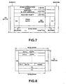
- the system log information for each partition is recorded in the system region of the leading side partition, thereby reducing the time required for recording/reproducing the system log for each partition.
- the tape system log information of each partition is recorded in the system region of the partition as main data, thereby improving system log reliability.
- the data streamer causes data to be recorded on and reproduced from an azimuth track on a magnetic tape by a rotary magnetic head and includes an interfacing controller 10 for data exchange with outside and a recording system signal processing section 20 for processing input data supplied to the data streamer via the interfacing controller 10 for conversion into signals of a pre-set format.
- the data streamer also includes a recording/reproducing section 30, a reproducing system signal processing section 40 and a tracking control section 50.
- the recording/reproducing section 30 records a signal supplied from the recording system signal processing section 20 by a pair of rotary magnetic heads 31A, 31B on azimuth tracks on a pair of rotary magnetic heads 31A, 31B and reproduces the signals recorded on the azimuth tracks by the rotary magnetic heads 31A, 31B.
- the reproducing system signal processing section 40 processes the playback signal from the recording/reproducing section 30 to reproduce the original data, while the tracking control section 50 controls the tape running system of the recording/reproducing section 30.
- the recording/reproducing section 30 has a rotary drum 31 made up of a pair of rotary magnetic heads 31A, 31B arranged at an angle of 180 relative to each other. On the peripheral surface of the rotary drum 31 is placed the magnetic tape 32 over an angle substantially equal to 90 and is run at a pre-set running velocity. During each complete revolution of the rotary drum 31, two azimuth tracks T A , T B on the magnetic tape 32 are scanned by the rotary magnetic heads 31A, 31B for recording/reproducing the signals, as shown in Fig.6.
- the error correction code generator 23 includes a memory 49, a C3 encoder 23A, a C2 encoder 23B and a C1 encoder 23C.
- the first subcode generating circuit 22A of the subcode generator 22 generates e.g., record counts indicating the number of records or separator counts as the main data partitioning information based upon data supplied thereto via the interfacing controller 10.
- the second subcode generating circuit 22B automatically generates area IDs indicating respective regions defined on a tape format, frame numbers, group counts indicating the number of recording units or the check sum, along with the block addresses.
- the system log generating circuit 22C also generates the system log (hysteresis information) for each of the partitions P1 and P2 prescribed as the tape formats.
- the data streamer having the above-described recording system signal processing section 20, splits one track into three regions, namely a main area and two margin areas on both ends of the main area.
- the data streamer also splits the main area into 64 blocks, each block being made up of 195 bytes.
- the data streamer divides each block into four portions, namely a one-byte first portion for recording a synchronization signal, a six-byte second portion for recording the sub-code and a block address, a 2-byte third portion for recording the header parity and a fourth portion for recording the data.
- the sub-code and the block address are recorded along with the main data.
- the block-based main data reliability may be improved by recording the error correction code C1 in this manner for each block, while the track-based main data reliability may be improved by recording the error correction code C2 for each block.
- the main area may be separated from the slide contact start/ end portion with respect to the rotary head to reduce the error otherwise produced in the data of the main area.
- both the system logs (hysteresis information) of the partitions P1 and P2 are recorded as the subcode in the system region of the partition P1.
- the access time may be shortened and a data streamer showing good operability may be achieved.
- the error correction unit 46 includes the above-mentioned memory 49, a C1 decoder 46A, a C2 decoder 46B and a C3 decoder 46C.
- the index separating circuit 47 separates the index information from the unit-based main data, which has been error-corrected by the error correcting unit 46, and routes the separated index information to e.g., a system controller, not shown.
- the block address detection circuit 51 detects the correct block address, parity-checked by the header parity check circuit 44, and routes a detection output indicating the detection timing to the time detection circuit 53.
- the PG detection circuit 52 detects the PG pulse indicating the rotational phase of the rotary drum 31 supplied from the recording/reproducing section 30 and routes a detection output indicating the detection timing to the time detection circuit 53.
- the time detection circuit 53 detects the time which elapses since the timing of detection of the pre-set block address by the block address detection circuit 51 until the timing of detection of the PG pulse by the PG detection circuit 52.
- the scanning distance from the tape edge of a track to a pre-set block is L in the just-tracking state, whereas the scanning distance is varied by ⁇ responsive to a tracking error, if there be any.
- the time detected by the time detection circuit 53 is varied depending on the tracking error as from the time for the just-tracking state.
- the tracking servo circuit 54 detects the time difference between the reference time corresponding to the time for the just-tracking state and the time detected by the time detection circuit 53, that is the tracking error, and controls the capstan driving circuit 55 driving the capstan motor of the tape running system of the recording/reproducing section 30, based upon the detection output, so that the tracking error will be reduced to zero.
- the system logs for the partitions P1 and P2, generated by the system log generating circuit 22C are recorded by the sub-code appending circuit 24 in the system region of the partition P1 as the subcode.
- the system logs of the partitions P1 and P2, generated by the system log generating circuit 22C are supplied to the C2 encoder 23B, and the system logs are recorded as main data in the system region of the partion P1.
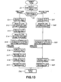
- the system controller 62 detects, at step S1, the tape format discriminating hole 35 provided in the tape cartridge 34 is detected by the tape format discrimination hole detector 61. At the next step S2, the system controller effects format discrimination of the magnetic tape 32 based upon the detection output.
- step S2 If the system controller 62 judges the tape format to be a first tape format or a second tape format at step S2, it transfers to step S11 or to step S21, respectively.
- the system controller 62 performs various control operations, such as data write/readout, and updates the system log on the memory depending on the contents of the control operations.
- the system controller 62 When the system controller 62 accepts an ejection command, it transfers to step S16 and causes the magnetic tape 32 to run as far as the system region of the second partition P2. At step S17, the system controller 62 records the system log information of the second partition P2 in the system region of the second partition P2. At the next step S18, the system controller causes the magnetic tape 32 to run as far as the system region of the first partition P1. At step S19, the system controller 62 records the system log information of the first partition P1 in the system region of the first partition P1. The system controller 62 then transfers to step S30 and ejects the tape cartridge 34 from the recording/reproducing section 30 to complete the control on the magnetic tape 32 of the first tape format.
- the system controller 62 When the system controller 62 accepts an ejection command, it transfers to step S24 and causes the magnetic tape 32 to run as far as the system region of the first partition P1. At step S19, the system controller 62 records the system log information of the first partition P1 and the system log information of the second partition P2 in the system region of the first partition P1. The system controller 62 then transfers to step S30 and ejects the tape cartridge 34 from the recording/reproducing section 30 to complete the control on the magnetic tape 32 of the second tape format.
- system logs of the partitions P1 and P of the magnetic tape 32 of the second tape format may be recorded as the sub-codes in the system region of the first partition, the system logs may be protected by the error correction code C2 if the system logs are recorded as main data, thereby improving system log reliability.
- the system logs of both the partitions P1 and P2 are recorded in the system region of the leading side partition P1
Landscapes
- Engineering & Computer Science (AREA)
- Signal Processing (AREA)
- Signal Processing For Digital Recording And Reproducing (AREA)
Claims (8)
- Datenaufzeichnungsverfahren für ein bandförmiges Aufzeichnungsmedium, welches aufweist:Aufzeichnen von Daten, um mehrere Azimuthspuren auf dem bandförmigen Aufzeichnungsmedium (32) durch einen Drehkopf (31A, 31B) zu bilden, wobei jede Azimuthspur Bereiche hat, um Subcodedaten aufzuzeichnen, und Bereiche, Hauptdaten und Fehlerkorrekturcodes für die Hauptdaten aufzuzeichnen, wobei die Fehlerkorrekturcodes an den Hauptdaten angehängt sind;Anordnen der mehreren Azimuthspuren, um mehrere Partitionen längs der Länge des Mediums zu bilden, wobei die Startpartition der mehreren Partitionen einen Systembereich hat; undAufzeichnen - als Hauptdaten - der entsprechenden Systemprotokollinformationen jeder Partition der mehreren Partitionen in den Bereichen, um Hauptdaten im Systembereich der Startpartition der mehreren Partitionen aufzuzeichnen, in einer Weise, dass die Systemprotokollinformation durch die Fehlerkorrekturcodes geschützt wird.
- Datenaufzeichnungsverfahren nach Anspruch 1, wobei:jede Partition der mehreren Partitionen zumindest einen Systembereich und einen Datenbereich hat.
- Datenaufzeichnungsverfahren für ein bandförmiges Aufzeichnungsmedium (32), in welchem Daten aufgezeichnet werden, um darauf mehrere Azimuthspuren durch einen Drehkopf (31A, 31B) zu bilden, wobei das Verfahren aufweist:Unterscheiden der Art des geladenen bandförmigen Aufzeichnungsmediums (32);Aufzeichnen von Systemprotokollinformation für mehrere Partitionen in einem Systembereich jeder Partition, wenn das Unterscheidungsergebnis zeigt, dass das geladene bandförmige Aufzeichnungsmedium (32) ein bandförmiges Aufzeichnungsmedium (32) eines ersten Aufzeichnungsformats ist; undAufzeichnen der Systemprotokollinformation gemäß dem Datenaufzeichnungsverfahren nach Anspruch 1, wenn das Unterscheidungsergebnis zeigt, dass das geladene bandförmige Aufzeichnungsmedium ein bandförmiges Aufzeichnungsmedium eines zweiten Aufzeichnungsformats ist.
- Datenaufzeichnungsverfahren nach Anspruch 3, wobei die mehreren Partitionen des ersten Aufzeichnungsformats jeweils zumindest einen Systembereich und einen Datenbereich haben, wobei die Systemprotokollinformation im Systembereich jeder Partition aufgezeichnet wird; und
die mehreren Partitionen des zweiten Aufzeichnungsformats jeweils zumindest einen Systembereich und einen Datenbereich haben. - Datenaufzeichnungsverfahren nach Anspruch 3 oder 4, wobei die Systemprotokollinformation für jede Partition als Hauptdaten im Systembereich jeder Partition aufgezeichnet wird, wenn das geladene bandförmige Aufzeichnungsmedium (32) das bandförmige Aufzeichnungsmedium (32) des ersten Aufzeichnungsformats ist, und als Hauptdaten im Systembereich der Startpartition aufgezeichnet wird, wenn das geladene bandförmige Aufzeichnungsmedium (32) das bandförmige Aufzeichnungsmedium (32) des zweiten Aufzeichnungsformats ist.
- Datenaufzeichnungsverfahren nach einem der vorhergehenden Ansprüche, wobei jede Spur des bandförmigen Aufzeichnungsmediums (32) durch einen Hauptbereich und Grenzbereiche gebildet ist, welche auf beiden Seiten des Hauptbereichs vorgesehen sind;
wobei der Hauptbereich jeder Spur durch mehrere Blöcke gebildet ist;
wobei jeder der Blöcke aus einem Bereich zum Aufzeichnen eines Synchronisationssignals, einem von den Bereichen zum Aufzeichnen von Subcodedaten und einem von den Bereichen zum Aufzeichnen von Hauptdaten besteht. - Bandförmiges Aufzeichnungsmedium (32), welches Informationsdaten speichert, wobei das Medium (32) Bereiche zum Aufzeichnen von Subcodedaten, und Bereiche zum Aufzeichnen von Hauptdaten hat, wobei Fehlerkorrekturcodes den Hauptdaten angehängt sind, und wobei dies aus mehreren Partitionen besteht, wobei jede Partition zumindest durch einen Datenbereich gebildet ist, auf welchem Informationsdaten aufgezeichnet sind, wobei
entsprechende Systemprotokollinformationen jeder Partition der mehreren Partitionen als Hauptdaten in Bereichen zum Aufzeichnen von Hauptdaten in einem Systembereich der startseitigen Partition des bandförmigen Aufzeichnungsmedium aufgezeichnet sind. - Aufzeichnungsvorrichtung für ein bandförmiges Aufzeichnungsmedium (32), welches Bereiche hat, um Subcodedaten aufzuzeichnen, und Bereiche hat, um Hauptdaten aufzuzeichnen, wobei Fehlerkorrekturcodes den Hauptdaten angehängt sind, und mehrere Partitionen hat, wobei jede Partition zumindest durch einen Datenbereich gebildet ist, auf welchem Informationsdaten aufgezeichnet sind, wobei die Vorrichtung aufweist:einen Drehkopf (31A, 31B) zum Aufzeichnen und/oder Wiedergaben von Daten in und/oder von dem bandförmigen Aufzeichnungsmedium (32);eine Speichereinrichtung (22c), um darin Systemprotokollinformation für jede Partition zu speichern, welche von dem bandförmigen Aufzeichnungsmedium (32) durch den Drehkopf (31A, 31B) gelesen wird; und eine Steuereinrichtung (10) zum Durchführen von Steuerung, um die Systemprotokollinformation, welche in der Speichereinrichtung gespeichert ist, auf Basis des Aufzeichnens und/oder des Wiedergebens von Daten in und/oder von dem bandförmigen Medium zu aktualisieren; wobeidie Vorrichtung für ein bandförmiges Aufzeichnungsmedium (32) ist, welches entsprechende Systemprotokollinformationen jeder Partition der mehreren Partitionen hat, welche als Hauptdaten in den Bereichen für das Aufzeichnen für Hauptdaten in einem Systembereich der Startpartition des bandförmigen Aufzeichnungsmediums (32) aufgezeichnet sind; unddie Steuereinrichtung zusätzlich dazu ist, um eine Steuerung durchzuführen, um auf die Startpartition des bandförmigen Aufzeichnungsmediums (32) zuzugreifen, bevor das bandförmige Aufzeichnungsmedium (32) von der Vorrichtung ausgeworfen wird, und um als Hauptdaten die Systemprotokollinformation für jede Partition, welche in der Speichereinrichtung gespeichert ist, aufzuzeichnen.
Applications Claiming Priority (2)
| Application Number | Priority Date | Filing Date | Title |
|---|---|---|---|
| JP175530/94 | 1994-07-27 | ||
| JP17553094A JP3871351B2 (ja) | 1994-03-15 | 1994-07-27 | データ記録方法 |
Publications (3)
| Publication Number | Publication Date |
|---|---|
| EP0694922A2 EP0694922A2 (de) | 1996-01-31 |
| EP0694922A3 EP0694922A3 (de) | 1996-12-11 |
| EP0694922B1 true EP0694922B1 (de) | 2007-12-12 |
Family
ID=15997684
Family Applications (1)
| Application Number | Title | Priority Date | Filing Date |
|---|---|---|---|
| EP95305214A Expired - Lifetime EP0694922B1 (de) | 1994-07-27 | 1995-07-26 | Datenaufzeichnungsverfahren |
Country Status (5)
| Country | Link |
|---|---|
| US (4) | US5828507A (de) |
| EP (1) | EP0694922B1 (de) |
| KR (1) | KR100385665B1 (de) |
| DE (1) | DE69535662T2 (de) |
| MY (1) | MY126291A (de) |
Families Citing this family (8)
| Publication number | Priority date | Publication date | Assignee | Title |
|---|---|---|---|---|
| US6252129B1 (en) | 1996-07-23 | 2001-06-26 | Electrosols, Ltd. | Dispensing device and method for forming material |
| JPH11154377A (ja) * | 1997-09-17 | 1999-06-08 | Sony Corp | データ記録装置及び方法、並びにデータ再生装置及び方法 |
| EP0984451B1 (de) | 1998-07-09 | 2005-12-14 | Hewlett-Packard Company, A Delaware Corporation | Verbessertes Datenschreiben auf Datenspeichermedium |
| KR100326338B1 (ko) * | 1999-09-18 | 2002-03-08 | 구자홍 | 광기록매체의 최적 기록방법 |
| US6937411B2 (en) * | 2001-08-06 | 2005-08-30 | International Business Machines Corporation | Method, system, program, and storage cartridge for storing data in a storage medium |
| GB2418770B (en) * | 2004-10-02 | 2009-04-22 | Hewlett Packard Development Co | Data storage apparatus and method |
| GB2422476B (en) * | 2005-01-21 | 2007-05-23 | Hewlett Packard Development Co | Data structure data storage apparatus and method |
| US8576505B2 (en) * | 2005-10-28 | 2013-11-05 | Hewlett-Packard Development Company, L.P. | Tape drive apparatus and method |
Family Cites Families (9)
| Publication number | Priority date | Publication date | Assignee | Title |
|---|---|---|---|---|
| JP2576512B2 (ja) * | 1987-06-29 | 1997-01-29 | ソニー株式会社 | デ−タレコ−ダ |
| GB8800349D0 (en) * | 1988-01-08 | 1988-02-10 | Hewlett Packard Ltd | Method of storing data on recording tape |
| GB8905435D0 (en) * | 1989-03-09 | 1989-04-19 | Hewlett Packard Ltd | Data storage apparatus |
| EP0429727B1 (de) * | 1989-11-30 | 1996-01-17 | Sony Corporation | Datenrecorder |
| NL9000039A (nl) * | 1990-01-08 | 1991-08-01 | Philips Nv | Digitaal transmissiesysteem, zender en ontvanger te gebruiken in het transmissiesysteem en registratiedrager verkregen met de zender in de vorm van een optekeninrichting. |
| US5406425A (en) * | 1991-08-06 | 1995-04-11 | R-Byte, Inc. | ISO/IEC compatible digital audio tape digital data storage system with increased data transfer rate |
| US5287478A (en) * | 1991-08-06 | 1994-02-15 | R-Byte, Inc. | Digital data tape storage system utilizing plurality of read/write heads with system diagnostic capability |
| JP2755370B2 (ja) * | 1991-10-30 | 1998-05-20 | インターナショナル・ビジネス・マシーンズ・コーポレイション | 周辺記憶システム及びデータ処理システムの制御方法 |
| JP3482676B2 (ja) * | 1994-03-15 | 2003-12-22 | ソニー株式会社 | データ記録方法及びデータ記録装置 |
-
1995
- 1995-07-25 US US08/507,670 patent/US5828507A/en not_active Expired - Lifetime
- 1995-07-26 DE DE69535662T patent/DE69535662T2/de not_active Expired - Lifetime
- 1995-07-26 EP EP95305214A patent/EP0694922B1/de not_active Expired - Lifetime
- 1995-07-27 MY MYPI95002161A patent/MY126291A/en unknown
- 1995-07-27 KR KR1019950023602A patent/KR100385665B1/ko not_active Expired - Lifetime
-
1996
- 1996-10-29 US US08/739,690 patent/US5930064A/en not_active Expired - Lifetime
- 1996-10-29 US US08/739,519 patent/US5930061A/en not_active Expired - Lifetime
- 1996-10-29 US US08/739,689 patent/US5862008A/en not_active Expired - Lifetime
Also Published As
| Publication number | Publication date |
|---|---|
| EP0694922A2 (de) | 1996-01-31 |
| DE69535662T2 (de) | 2008-12-04 |
| US5828507A (en) | 1998-10-27 |
| US5930064A (en) | 1999-07-27 |
| US5930061A (en) | 1999-07-27 |
| KR100385665B1 (ko) | 2003-08-21 |
| EP0694922A3 (de) | 1996-12-11 |
| MY126291A (en) | 2006-09-29 |
| DE69535662D1 (de) | 2008-01-24 |
| US5862008A (en) | 1999-01-19 |
Similar Documents
| Publication | Publication Date | Title |
|---|---|---|
| EP0323890B1 (de) | Datenspeicherverfahren | |
| EP0902425B1 (de) | Bandaufzeichnungs- und/oder -wiedergabegerät sowie Bandauswurfverfahren | |
| US5091805A (en) | Apparatus and method for recording and/or reproducing a digital signal | |
| US4935824A (en) | Information recording apparatus | |
| EP0429727B1 (de) | Datenrecorder | |
| US5134529A (en) | Apparatus and method for recording a digital signal | |
| EP0673031B1 (de) | Verfahren und Gerät zur Aufzeichnung und/oder Wiedergabe von Daten, und bandförmiges Aufzeichnungsmedium | |
| US5828507A (en) | Method for recording data onto tape-shaped recording media for high-speed retrieval based on system log information recorded in a leading partition | |
| US5818652A (en) | Device for reproducing a recording medium having plural recording areas | |
| US6141164A (en) | Data recording/reproducing apparatus employing read-after-write system | |
| EP0287376B1 (de) | Aufzeichnung und/oder Wiedergabe von Datensignalen | |
| EP0327201B1 (de) | Daten-Aufzeichnungsvorrichtung und Verfahren zur Aufzeichnung von digitalen Daten | |
| US5144500A (en) | Method and apparatus for reproducing multiply recorded data | |
| EP0323911B1 (de) | Aufzeichnung digitaler Signale | |
| US5144501A (en) | Data recorder and method of operation | |
| JP3477795B2 (ja) | データ記録方法、データ記録媒体及びデータストリーマ | |
| JP3871351B2 (ja) | データ記録方法 | |
| JP2805703B2 (ja) | データ記録方法 | |
| CA1325270C (en) | Apparatus and method for recording and/or reproducing a digital signal | |
| GB2333886A (en) | Device for reproducing from a recording medium having plural recording areas |
Legal Events
| Date | Code | Title | Description |
|---|---|---|---|
| PUAI | Public reference made under article 153(3) epc to a published international application that has entered the european phase |
Free format text: ORIGINAL CODE: 0009012 |
|
| AK | Designated contracting states |
Kind code of ref document: A2 Designated state(s): DE FR GB |
|
| PUAL | Search report despatched |
Free format text: ORIGINAL CODE: 0009013 |
|
| AK | Designated contracting states |
Kind code of ref document: A3 Designated state(s): DE FR GB |
|
| 17P | Request for examination filed |
Effective date: 19970513 |
|
| 17Q | First examination report despatched |
Effective date: 19970624 |
|
| GRAP | Despatch of communication of intention to grant a patent |
Free format text: ORIGINAL CODE: EPIDOSNIGR1 |
|
| GRAS | Grant fee paid |
Free format text: ORIGINAL CODE: EPIDOSNIGR3 |
|
| GRAA | (expected) grant |
Free format text: ORIGINAL CODE: 0009210 |
|
| AK | Designated contracting states |
Kind code of ref document: B1 Designated state(s): DE FR GB |
|
| REG | Reference to a national code |
Ref country code: GB Ref legal event code: FG4D |
|
| REF | Corresponds to: |
Ref document number: 69535662 Country of ref document: DE Date of ref document: 20080124 Kind code of ref document: P |
|
| ET | Fr: translation filed | ||
| PLBE | No opposition filed within time limit |
Free format text: ORIGINAL CODE: 0009261 |
|
| STAA | Information on the status of an ep patent application or granted ep patent |
Free format text: STATUS: NO OPPOSITION FILED WITHIN TIME LIMIT |
|
| 26N | No opposition filed |
Effective date: 20080915 |
|
| REG | Reference to a national code |
Ref country code: GB Ref legal event code: 746 Effective date: 20120703 |
|
| REG | Reference to a national code |
Ref country code: DE Ref legal event code: R084 Ref document number: 69535662 Country of ref document: DE Effective date: 20120614 |
|
| PGFP | Annual fee paid to national office [announced via postgrant information from national office to epo] |
Ref country code: DE Payment date: 20140721 Year of fee payment: 20 |
|
| PGFP | Annual fee paid to national office [announced via postgrant information from national office to epo] |
Ref country code: FR Payment date: 20140721 Year of fee payment: 20 Ref country code: GB Payment date: 20140721 Year of fee payment: 20 |
|
| REG | Reference to a national code |
Ref country code: DE Ref legal event code: R071 Ref document number: 69535662 Country of ref document: DE |
|
| REG | Reference to a national code |
Ref country code: GB Ref legal event code: PE20 Expiry date: 20150725 |
|
| PG25 | Lapsed in a contracting state [announced via postgrant information from national office to epo] |
Ref country code: GB Free format text: LAPSE BECAUSE OF EXPIRATION OF PROTECTION Effective date: 20150725 |