EP0694937A2 - Procédé et dispositif pour déterminer la vie résiduelle de contacts dans les appareils de commutation - Google Patents
Procédé et dispositif pour déterminer la vie résiduelle de contacts dans les appareils de commutation Download PDFInfo
- Publication number
- EP0694937A2 EP0694937A2 EP95111202A EP95111202A EP0694937A2 EP 0694937 A2 EP0694937 A2 EP 0694937A2 EP 95111202 A EP95111202 A EP 95111202A EP 95111202 A EP95111202 A EP 95111202A EP 0694937 A2 EP0694937 A2 EP 0694937A2
- Authority
- EP
- European Patent Office
- Prior art keywords
- contact
- armature
- switching
- rld
- remaining
- Prior art date
- Legal status (The legal status is an assumption and is not a legal conclusion. Google has not performed a legal analysis and makes no representation as to the accuracy of the status listed.)
- Granted
Links
Images
Classifications
-
- H—ELECTRICITY
- H01—ELECTRIC ELEMENTS
- H01H—ELECTRIC SWITCHES; RELAYS; SELECTORS; EMERGENCY PROTECTIVE DEVICES
- H01H1/00—Contacts
- H01H1/0015—Means for testing or for inspecting contacts, e.g. wear indicator
-
- H—ELECTRICITY
- H01—ELECTRIC ELEMENTS
- H01H—ELECTRIC SWITCHES; RELAYS; SELECTORS; EMERGENCY PROTECTIVE DEVICES
- H01H47/00—Circuit arrangements not adapted to a particular application of the relay and designed to obtain desired operating characteristics or to provide energising current
- H01H47/002—Monitoring or fail-safe circuits
-
- H—ELECTRICITY
- H01—ELECTRIC ELEMENTS
- H01H—ELECTRIC SWITCHES; RELAYS; SELECTORS; EMERGENCY PROTECTIVE DEVICES
- H01H71/00—Details of the protective switches or relays covered by groups H01H73/00 - H01H83/00
- H01H71/04—Means for indicating condition of the switching device
- H01H2071/044—Monitoring, detection or measuring systems to establish the end of life of the switching device, can also contain other on-line monitoring systems, e.g. for detecting mechanical failures
-
- H—ELECTRICITY
- H01—ELECTRIC ELEMENTS
- H01H—ELECTRIC SWITCHES; RELAYS; SELECTORS; EMERGENCY PROTECTIVE DEVICES
- H01H3/00—Mechanisms for operating contacts
- H01H3/001—Means for preventing or breaking contact-welding
Definitions
- the invention relates to a method for determining the remaining service life of contacts in switching devices, in particular contactor contacts, in which the contact pieces are subject to erosion when switching, a replacement criterion for the erosion being recorded and evaluated.
- the contact pieces burn up each time they switch. Depending on the stress caused by the current or the voltage, this erosion ultimately leads to the failure of the switching device, so that its service life is limited. Under certain operating conditions, the contact pieces or the entire switching device are currently exchanged after a routinely determined number of switching operations, regardless of whether extensive contact with the contact pieces actually occurred or not.
- Proposals are already known from the prior art, in which more or less the remaining service life of contactors is derived from the operating time and / or from the number of switching cycles.
- the electrical service life is defined by empirical values and by the device type, the electrical load and e.g. depending on the contact material. If one or more influencing variables change, a new empirical value must be determined for the electrical life of the switching device.
- replacement criteria for the erosion are selected and evaluated for the determination of the remaining service life of contact pieces.
- a switching device is known from DE-AS 23 05 149, in which the change in length of the switching stroke caused by the contact erosion is detected.
- a relatively complex mechanical construction is required.
- an electrical switch is known in which at least one of the contact pieces is assigned a light guide, the transmission properties of which can be measured from the outside by means of suitable optical auxiliary devices.
- the object of the invention is to provide a simplified method and an associated arrangement with which a reliable determination of the remaining service life can be determined.
- the so-called contact pressure of the switching bridge is selected as a substitute criterion and that the pressure change during the switching-off process is determined and the remaining service life is calculated to determine the erosion of the contact pieces.
- the change in pressure pressure is preferably determined from the time measurement of the armature path from the beginning of the armature opening movement to the beginning of the contact opening.
- the determination of the remaining service life can be carried out in software according to the given equation.
- the remaining operating time and / or the remaining number of switching operations of the switching device can be calculated from correspondingly derived equations.
- an arrangement is advantageously characterized by a processor unit with memories and a controller and an associated display. If necessary, appropriate display means can be present on the switching device itself.
- the change in the contact pressure is in principle based on the measurement of time differences from the switching off of the magnet system, ie exactly from the beginning of the armature opening, to to open the bridge contacts is based, which can be done in a simple manner.
- the measurement variables arising can thus be used to clearly indicate the switching status of the contactor.
- the switch-on status can be clearly identified by touching the pole faces of the armature and yoke. This contact can be measured as an electrical contact between armature and yoke, for which purpose the armature and yoke are connected to an auxiliary circuit via resilient contacts.
- the armature In the regular switch-off state of the contactor, on the other hand, the armature is in its open position and the electrical contact between the pole faces of the armature and yoke is interrupted. Even in the case of contact welding, where bridge contacts can be welded on one or two sides, the armature moves away from the yoke by at least a fraction of the contact pressure when the contactor is switched off. The electrical contact between the pole faces of the armature and yoke is also interrupted here.
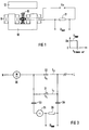
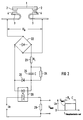
- Figures 1 and 2 each show parts of a contactor with the associated measuring device.
- 1 shows the magnetic drive and
- FIG. 2 shows the contact arrangement of the associated contactor.
- 1 means a switching bridge with two contact pieces 2 arranged thereon at the ends and 3 U-shaped cranked contact carriers with mating contacts 4 arranged thereon for the contacts 2 of the switching bridge 1.
- the associated drive essentially consists of a magnetic yoke 10 with coils 11 attached to it and one Associated magnet armature 12.
- the magnet armature is connected to a receiving device, the bridge support, for receiving the switching bridges, which is not shown in FIG. 1 or FIG. 2.
- the times t0 and t i can be determined with associated electrical switching elements.
- the magnet armature 12 and the magnet yoke 11 are connected to the direct voltage U0 of an auxiliary circuit via resilient contacts 15 and a measuring resistor 21 with resistance R measurement .
- the magnetic yoke 11 can also be connected to the auxiliary circuit via a flexible or rigid electrical line instead of via a resilient contact 15. If the armature 12 touches the yoke 10, the auxiliary circuit is closed and the voltage U0 drops across the measuring resistor 21. When the armature 12 is lifted from the yoke 10, the current path across the pole faces is interrupted and the voltage across the measuring resistor changes from U0 to zero. The voltage edge U0 ⁇ 0 is further processed in an evaluation device as time t0.
- the determination of the contact opening times t i can be derived from FIG. It is assumed that the main contacts 2 and 4 of the contactor open under current load and arcing arises.
- To measure the contact opening times is when opening a main contact resulting switching voltage, ie the arc voltage of short arcs, rectified in a rectifier circuit 22 and supplied to the control input of an optocoupler 28 via a limiting circuit comprising resistors 23 and 24 and capacitor 25 and associated zener diode 26.
- the switching output of the optocoupler 28 switches an auxiliary circuit, which consists of a measuring resistor 29 and a DC voltage source U0.
- the contactor is switched off when there is no current, for example when switching three-phase asynchronous motors without interruption or when starting three-phase asynchronous motors automatically via three-pole resistors with time relays, instead of an arrangement according to FIG. 2, an arrangement corresponding to FIG use.
- the contact opening times when the main contacts to be monitored are opened without current can be determined by the inductance measurement, for example if the mains voltage is interrupted or if there are parallel current paths to the main contacts.
- Figure 3 has a motor as a load, which is electrically connected in series to a parallel connection of a main contact S1 of a contactor 31 with a main contact S2 of a contactor 32, the switching paths connected in parallel capacitively to capacitors 33 and 34 with capacitance C o Auxiliary circuit with generator 35 and resistor 36 are connected. Parallel connections of this type are used in particular for a transition contactor.
- a damped resonant circuit is therefore connected to the main contact to be monitored, which is fed via the higher-frequency generator 35 at a frequency of, for example, 1 to 10 MHz.
- the generator frequency, the capacitance and the inductance of the resonant circuit are set approximately to resonance.
- L1 0.3 ⁇ H
- L2 0.8 ⁇ H
- L2 0.8 ⁇ H
- the determined times t0 and t i are used to determine the remaining service life.
- the following considerations can be made to derive a suitable relationship:
- the contact forces of the switching bridges add up with the spring force of the armature springs to the total opening force F A of the magnet armature 10.
- this force F A provides a practical constant armature acceleration until the opening of the bridge contacts begins.
- the switching load of the contactor main contacts 2 or 4 is different, for example in a 3-phase network, the main contacts 2, 4 of each phase burn to different extents and the contact opening in the three phases takes place in chronological order, starting with the most burned-out contacts.
- the time average of the armature acceleration for the later opening, ie less burned main contacts, is therefore somewhat less than for the main contact opening first.
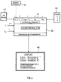
- 40 means a controller to which the time signals t0 and t i , ie their voltage edges from FIGS. 1 and 2, are supplied.
- the controller determines the number of operations N as further variables and, for example, the elapsed operating time T with an internal clock.
- the controller 40 can be used to monitor the mechanical state of wear determine the number of switching cycles N0 accumulated over several electrical life cycles.
- the controller 40 contains the geometry variable c as a constant input variable.
- the controller 40 determines the time difference t i -t0 from the time signals t0, t i , wherein the reference variable t i, neut -t characterizing the new state can be defined as the mean value of the time difference t i -t0 of a given number of switching cycles.
- the average of the first ten switching cycles of a service life cycle can be used.
- the current measurement data and evaluation variables are stored in non-volatile data memory 41 and are thus saved.
- input and output units 42 to 44 and a display for displaying the results are also input and output units 42 to 44 and a display for displaying the results.
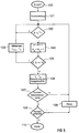
- controller 40 can now calculate Formula 1 using an evaluation program.
- further quantities characterizing the state of wear of the contactor can be calculated, such as a remaining operating time or a remaining number of operations.
- T the remaining operating time
- Rbd (days) T (days) * RLD [%] / (100-RLD) [%].
- the formulas (2) and (3) can be evaluated as soon as the remaining service life (Rld) determined according to formula (1) has reached a value ⁇ 100%.
- the controller 40 It is particularly favorable if the data of the remaining service life determined by the controller 40 are optically displayed on a display element attached to the switching device itself.
- the digitized evaluation variables can be transmitted from the controller 40 to a central monitoring unit (not shown) via a data bus.
- the measuring and evaluation device for determining the remaining service life of contacts in switchgear and monitoring for contact welding allows, under certain circumstances with the use of additional means, extended switchgear monitoring with regard to serious malfunctions, such as breakage of contact carriers and / or spring clips, unsoldering of contact pieces, impermissible contact resistances, excessive contact temperature and the like.
- the switching bridge would only give uncontrolled electrical contact when the contactor drive was switched on, so that a serious change in the time sequence of the measured variables t o (start of armature movement) and t i (start of contact opening) can be expected.
- the electrical power loss can be calculated by multiplying the measured contact voltage by, e.g. be specified with a current transformer, measured switch current, power limit values at which a fault message is issued if their level and duration are exceeded.
- Switching device diagnostics e.g. Can be carried out at any time and without gaps via a display element on the switching device or via data bus on a central evaluation device.
- the method described thus enables a clear statement to be made about the welding condition or the erosion of the main contacts and a necessary exchange of the contact pieces.
Landscapes
- Keying Circuit Devices (AREA)
- Manufacture Of Switches (AREA)
Applications Claiming Priority (2)
| Application Number | Priority Date | Filing Date | Title |
|---|---|---|---|
| DE4427006 | 1994-07-29 | ||
| DE4427006A DE4427006A1 (de) | 1994-07-29 | 1994-07-29 | Verfahren zur Bestimmung der Restlebensdauer von Kontakten in Schaltgeräten und zugehörige Anordnung |
Publications (3)
| Publication Number | Publication Date |
|---|---|
| EP0694937A2 true EP0694937A2 (fr) | 1996-01-31 |
| EP0694937A3 EP0694937A3 (fr) | 1997-08-13 |
| EP0694937B1 EP0694937B1 (fr) | 2000-03-29 |
Family
ID=6524513
Family Applications (1)
| Application Number | Title | Priority Date | Filing Date |
|---|---|---|---|
| EP95111202A Expired - Lifetime EP0694937B1 (fr) | 1994-07-29 | 1995-07-17 | Procédé et dispositif pour déterminer la vie résiduelle de contacts dans les appareils de commutation |
Country Status (3)
| Country | Link |
|---|---|
| EP (1) | EP0694937B1 (fr) |
| DE (2) | DE4427006A1 (fr) |
| ES (1) | ES2145185T3 (fr) |
Cited By (20)
| Publication number | Priority date | Publication date | Assignee | Title |
|---|---|---|---|---|
| DE19603310A1 (de) * | 1996-01-31 | 1997-08-07 | Siemens Ag | Verfahren zur Bestimmung der Restlebensdauer von Kontakten in Schaltgeräten und zugehörige Anordnung |
| WO1997028549A1 (fr) * | 1996-01-31 | 1997-08-07 | Siemens Aktiengesellschaft | Procede de determination de la duree de vie residuelle de contacts dans des appareils de commutation et systeme associe |
| WO1999008301A1 (fr) * | 1997-08-07 | 1999-02-18 | Siemens Aktiengesellschaft | Procede pour determiner des donnees specifiques d'appareils de commutation au niveau de contacts installes dans lesdits appareils de commutation et/ou donnees specifiques de fonctionnement dans un reseau commute de façon correspondante |
| DE19947105A1 (de) * | 1999-09-30 | 2001-05-03 | Siemens Ag | Anorndung zum Ein- und Ausschalten elektrischer Lastkreise |
| WO2002033716A1 (fr) * | 2000-10-16 | 2002-04-25 | Siemens Aktiengesellschaft | Procede et dispositif pour reduire l'usure des contacts d'un appareil de coupure |
| WO2004057633A1 (fr) * | 2002-12-20 | 2004-07-08 | Siemens Aktiengesellschaft | Procede pour determiner la duree de vie restante d'un appareil de commutation et systeme associe |
| WO2006069957A1 (fr) * | 2004-12-23 | 2006-07-06 | Siemens Aktiengesellschaft | Procede et dispositif pour assurer la securite de fonctionnement d'un appareil de distribution |
| WO2006069955A3 (fr) * | 2004-12-23 | 2006-08-24 | Siemens Ag | Procede et dispositif pour assurer la securite de fonctionnement d'un appareil de distribution |
| WO2008000105A1 (fr) * | 2006-06-26 | 2008-01-03 | Abb Technology Ag | Procédé pour déterminer l'érosion des contacts sur un disjoncteur à haut pouvoir de coupure |
| CN100413004C (zh) * | 2002-12-20 | 2008-08-20 | 西门子公司 | 用于确定开关装置剩余寿命的方法和设备 |
| EP2182537A1 (fr) * | 2008-10-31 | 2010-05-05 | Siemens AG | Circuits à relais |
| EP2200055A1 (fr) * | 2008-12-19 | 2010-06-23 | Schneider Electric Industries SAS | Appareil électrique interrupteur à fonctionnement optimisé |
| EP2383758A1 (fr) * | 2010-04-30 | 2011-11-02 | Schneider Electric Industries SAS | Actionneur électromagnétique à fonctionnement optimisé et appareil électrique interrupteur comportant un tel actionneur |
| US8688391B2 (en) | 2005-09-21 | 2014-04-01 | Siemens Aktiengelleschaft | Method for determining contact erosion of an electromagnetic switching device, and electromagnetic switching device comprising a mechanism operating according to said method |
| CN105632840A (zh) * | 2016-01-07 | 2016-06-01 | 温州大学 | 一种基于分断相位控制的智能交流接触器及其操作方法 |
| CN106663553A (zh) * | 2014-09-03 | 2017-05-10 | 伊莱克斯家用电器股份公司 | 用于操作继电器的设备、方法、电器以及计算机程序产品 |
| US10340640B2 (en) | 2017-05-04 | 2019-07-02 | Schneider Electric USA, Inc. | System and method for determining the current condition of power contacts |
| EP3971927A1 (fr) * | 2020-09-16 | 2022-03-23 | ABB Schweiz AG | Commande de contacteur |
| CN114600212A (zh) * | 2019-09-11 | 2022-06-07 | 电弧抑制技术公司 | 电力接触电极表面等离子体治疗 |
| CN114631162A (zh) * | 2019-09-11 | 2022-06-14 | 电弧抑制技术公司 | 电力接触寿命终止预测器设备 |
Families Citing this family (13)
| Publication number | Priority date | Publication date | Assignee | Title |
|---|---|---|---|---|
| DE19727986C2 (de) * | 1997-07-01 | 2001-10-11 | Moeller Gmbh | Schaltungsanordnung zur Ermittlung des Kontaktabbrandes von einem elektrischen Schaltgerät |
| DE19915978A1 (de) * | 1999-04-09 | 2000-10-12 | Abb Patent Gmbh | Verfahren zur Messung des Kontaktabbrandes eines Mittel- oder Hochspannungs-Leistungsschalters |
| DE19948551C1 (de) * | 1999-10-08 | 2001-07-05 | Siemens Ag | Verfahren zur Vergleichmäßigung von Gesamtabbränden eines elektromagnetischen Schaltgeräts und hiermit korrespondierendes elektromagnetisches Schaltgerät |
| DE10003918C1 (de) * | 2000-01-29 | 2001-07-05 | Reinhausen Maschf Scheubeck | Verfahren zur Überwachung des Kontaktabbrandes bei Stufenschaltern |
| DE10028559C1 (de) * | 2000-06-09 | 2001-11-22 | Siemens Ag | Elektromagnetisches Schaltgerät, insbesondere Schütz |
| DE10260258B4 (de) * | 2002-12-20 | 2005-02-24 | Siemens Ag | Verfahren und Vorrichtung zur Bestimmung der Restlebensdauer eines Schaltgerätes |
| DE102004062266A1 (de) | 2004-12-23 | 2006-07-13 | Siemens Ag | Verfahren und Vorrichtung zum sicheren Betrieb eines Schaltgerätes |
| BRPI0519197A2 (pt) | 2004-12-23 | 2008-12-30 | Siemens Ag | processo e dispositivo para a operaÇço segura de um aparelho de comutaÇço |
| DE102004062267A1 (de) | 2004-12-23 | 2006-07-13 | Siemens Ag | Verfahren und Vorrichtung zum sicheren Betrieb eines Schaltgerätes |
| FR3023963B1 (fr) | 2014-07-17 | 2018-03-09 | Schneider Electric Industries Sas | Procede de determination de l'usure des contacts electriques d'un appareil electrique interrupteur |
| DE102015121264A1 (de) * | 2015-12-07 | 2017-06-08 | Epcos Ag | Leistungsschütz und Verfahren zur Funktionsprüfung eines Leistungsschützes |
| US10763659B2 (en) | 2019-01-29 | 2020-09-01 | Arc Suppression Technologies | Power contact fault clearing device |
| WO2021050461A1 (fr) * | 2019-09-11 | 2021-03-18 | Arc Suppression Technologies | Évaluateur de santé de contact électrique |
Citations (3)
| Publication number | Priority date | Publication date | Assignee | Title |
|---|---|---|---|---|
| DE2305149A1 (de) | 1972-02-04 | 1973-08-09 | Jungbunzlauer Spiritus | Verfahren zur herstellung von trinatrium- bzw. trikaliumcitrat |
| DE3714802A1 (de) | 1987-05-04 | 1988-11-17 | Siemens Ag | Elektrischer schalter |
| DE4307177A1 (de) | 1993-03-08 | 1994-09-22 | Lueder Ernst | Schaltanordnung zur Ansteuerung von ketten- oder matrixförmig angeordneten Schaltelementen |
Family Cites Families (7)
| Publication number | Priority date | Publication date | Assignee | Title |
|---|---|---|---|---|
| DE1764678U (de) * | 1955-08-29 | 1958-04-10 | Siemens Ag | Anordnung zur ueberwachung des schaltstueckabbrandes. |
| DE1174877B (de) * | 1963-08-14 | 1964-07-30 | Siemens Ag | Leistungsschalter |
| DE1515546B1 (de) * | 1965-03-11 | 1970-08-20 | Calor-Emag Elektrizitaets-Ag | Elektrischer Schalter |
| GB2158253B (en) * | 1984-04-26 | 1987-06-17 | Ferranti Plc | Transformer tap changing switch wear monitor |
| CH668669A5 (de) * | 1985-10-08 | 1989-01-13 | Sprecher Energie Ag | Verfahren zum ermitteln des abbrandes der kontaktstuecke eines in einer gekapselten schaltanlage eingebauten schaltgeraetes. |
| JPH01206531A (ja) * | 1988-02-12 | 1989-08-18 | Fuji Electric Co Ltd | 電磁接触器の接点消耗検出装置 |
| DE4028721C2 (de) * | 1990-09-10 | 1995-05-11 | Siemens Ag | Verfahren und Anordnung zur Ermittlung der Restlebensdauer von Schaltgeräten |
-
1994
- 1994-07-29 DE DE4427006A patent/DE4427006A1/de not_active Withdrawn
-
1995
- 1995-07-17 ES ES95111202T patent/ES2145185T3/es not_active Expired - Lifetime
- 1995-07-17 DE DE59508081T patent/DE59508081D1/de not_active Expired - Lifetime
- 1995-07-17 EP EP95111202A patent/EP0694937B1/fr not_active Expired - Lifetime
Patent Citations (3)
| Publication number | Priority date | Publication date | Assignee | Title |
|---|---|---|---|---|
| DE2305149A1 (de) | 1972-02-04 | 1973-08-09 | Jungbunzlauer Spiritus | Verfahren zur herstellung von trinatrium- bzw. trikaliumcitrat |
| DE3714802A1 (de) | 1987-05-04 | 1988-11-17 | Siemens Ag | Elektrischer schalter |
| DE4307177A1 (de) | 1993-03-08 | 1994-09-22 | Lueder Ernst | Schaltanordnung zur Ansteuerung von ketten- oder matrixförmig angeordneten Schaltelementen |
Cited By (38)
| Publication number | Priority date | Publication date | Assignee | Title |
|---|---|---|---|---|
| DE19603310A1 (de) * | 1996-01-31 | 1997-08-07 | Siemens Ag | Verfahren zur Bestimmung der Restlebensdauer von Kontakten in Schaltgeräten und zugehörige Anordnung |
| WO1997028549A1 (fr) * | 1996-01-31 | 1997-08-07 | Siemens Aktiengesellschaft | Procede de determination de la duree de vie residuelle de contacts dans des appareils de commutation et systeme associe |
| WO1997028548A1 (fr) * | 1996-01-31 | 1997-08-07 | Siemens Aktiengesellschaft | Procede de determination de la duree de vie residuelle de contacts dans des appareils de commutation et systeme associe |
| CN1065352C (zh) * | 1996-01-31 | 2001-05-02 | 西门子公司 | 确定开关设备内触点剩余寿命的方法及相应的装置 |
| CN1068956C (zh) * | 1996-01-31 | 2001-07-25 | 西门子公司 | 确定开关设备中触点剩余寿命的方法及相应的装置 |
| WO1999008301A1 (fr) * | 1997-08-07 | 1999-02-18 | Siemens Aktiengesellschaft | Procede pour determiner des donnees specifiques d'appareils de commutation au niveau de contacts installes dans lesdits appareils de commutation et/ou donnees specifiques de fonctionnement dans un reseau commute de façon correspondante |
| US6313636B1 (en) | 1997-08-07 | 2001-11-06 | Siemens Aktiengesellschaft | Method for determining switchgear-specific data at contacts in switchgear and/or operation-specific data in a network connected to the switchgear and apparatus for carrying out the method |
| DE19947105A1 (de) * | 1999-09-30 | 2001-05-03 | Siemens Ag | Anorndung zum Ein- und Ausschalten elektrischer Lastkreise |
| DE19947105C2 (de) * | 1999-09-30 | 2002-01-24 | Siemens Ag | Verfahren und zugehörige Anordnungen zum Schalten elektrischer Lastkreise |
| WO2002033716A1 (fr) * | 2000-10-16 | 2002-04-25 | Siemens Aktiengesellschaft | Procede et dispositif pour reduire l'usure des contacts d'un appareil de coupure |
| WO2004057633A1 (fr) * | 2002-12-20 | 2004-07-08 | Siemens Aktiengesellschaft | Procede pour determiner la duree de vie restante d'un appareil de commutation et systeme associe |
| CN100413004C (zh) * | 2002-12-20 | 2008-08-20 | 西门子公司 | 用于确定开关装置剩余寿命的方法和设备 |
| WO2006069957A1 (fr) * | 2004-12-23 | 2006-07-06 | Siemens Aktiengesellschaft | Procede et dispositif pour assurer la securite de fonctionnement d'un appareil de distribution |
| WO2006069955A3 (fr) * | 2004-12-23 | 2006-08-24 | Siemens Ag | Procede et dispositif pour assurer la securite de fonctionnement d'un appareil de distribution |
| US7978036B2 (en) | 2004-12-23 | 2011-07-12 | Siemens Aktiengesellschaft | Method and device for the secure operation of a switching device |
| CN101080790B (zh) * | 2004-12-23 | 2010-12-08 | 西门子公司 | 使开关设备安全工作的方法和装置 |
| US8688391B2 (en) | 2005-09-21 | 2014-04-01 | Siemens Aktiengelleschaft | Method for determining contact erosion of an electromagnetic switching device, and electromagnetic switching device comprising a mechanism operating according to said method |
| WO2008000105A1 (fr) * | 2006-06-26 | 2008-01-03 | Abb Technology Ag | Procédé pour déterminer l'érosion des contacts sur un disjoncteur à haut pouvoir de coupure |
| DE202007018709U1 (de) | 2006-06-26 | 2009-03-26 | Abb Technology Ag | Bestimmung und Anzeige des Kontaktabrandes an einem Hochleistungsschalter |
| EP2182537A1 (fr) * | 2008-10-31 | 2010-05-05 | Siemens AG | Circuits à relais |
| FR2940509A1 (fr) * | 2008-12-19 | 2010-06-25 | Schneider Electric Ind Sas | Appareil electrique interrupteur a fonctionnement optimise |
| EP2200055A1 (fr) * | 2008-12-19 | 2010-06-23 | Schneider Electric Industries SAS | Appareil électrique interrupteur à fonctionnement optimisé |
| EP2383758A1 (fr) * | 2010-04-30 | 2011-11-02 | Schneider Electric Industries SAS | Actionneur électromagnétique à fonctionnement optimisé et appareil électrique interrupteur comportant un tel actionneur |
| FR2959589A1 (fr) * | 2010-04-30 | 2011-11-04 | Schneider Electric Ind Sas | Actionneur electromagnetique a fonctionnement optimise et appareil electrique interrupteur comportant un tel actionneur. |
| US10573476B2 (en) | 2014-09-03 | 2020-02-25 | Electrolux Appliances Aktiebolag | Apparatus, method, appliance, and computer program product for operating a relay |
| CN106663553B (zh) * | 2014-09-03 | 2019-05-03 | 伊莱克斯家用电器股份公司 | 用于操作继电器的设备、方法、电器以及计算机程序产品 |
| CN106663553A (zh) * | 2014-09-03 | 2017-05-10 | 伊莱克斯家用电器股份公司 | 用于操作继电器的设备、方法、电器以及计算机程序产品 |
| CN105632840B (zh) * | 2016-01-07 | 2018-07-24 | 温州大学 | 一种基于分断相位控制的智能交流接触器及其操作方法 |
| CN105632840A (zh) * | 2016-01-07 | 2016-06-01 | 温州大学 | 一种基于分断相位控制的智能交流接触器及其操作方法 |
| US10340640B2 (en) | 2017-05-04 | 2019-07-02 | Schneider Electric USA, Inc. | System and method for determining the current condition of power contacts |
| CN114600212A (zh) * | 2019-09-11 | 2022-06-07 | 电弧抑制技术公司 | 电力接触电极表面等离子体治疗 |
| CN114631162A (zh) * | 2019-09-11 | 2022-06-14 | 电弧抑制技术公司 | 电力接触寿命终止预测器设备 |
| WO2022058089A1 (fr) * | 2020-09-16 | 2022-03-24 | Abb Schweiz Ag | Contrôle de contacteur |
| EP3971927A1 (fr) * | 2020-09-16 | 2022-03-23 | ABB Schweiz AG | Commande de contacteur |
| KR20230066579A (ko) * | 2020-09-16 | 2023-05-16 | 에이비비 슈바이쯔 아게 | 접촉기 제어 |
| CN116325055A (zh) * | 2020-09-16 | 2023-06-23 | Abb瑞士股份有限公司 | 接触器控制 |
| US11887795B2 (en) | 2020-09-16 | 2024-01-30 | Abb Schweiz Ag | Contactor control |
| CN116325055B (zh) * | 2020-09-16 | 2024-05-28 | Abb瑞士股份有限公司 | 接触器控制 |
Also Published As
| Publication number | Publication date |
|---|---|
| EP0694937B1 (fr) | 2000-03-29 |
| DE59508081D1 (de) | 2000-05-04 |
| ES2145185T3 (es) | 2000-07-01 |
| DE4427006A1 (de) | 1996-02-01 |
| EP0694937A3 (fr) | 1997-08-13 |
Similar Documents
| Publication | Publication Date | Title |
|---|---|---|
| EP0694937B1 (fr) | Procédé et dispositif pour déterminer la vie résiduelle de contacts dans les appareils de commutation | |
| EP1002325B1 (fr) | PROCEDE POUR DETERMINER DES DONNEES SPECIFIQUES D'APPAREILS DE COMMUTATION AU NIVEAU DE CONTACTS INSTALLES DANS LESDITS APPAREILS DE COMMUTATION ET/OU DONNEES SPECIFIQUES DE FONCTIONNEMENT DANS UN RESEAU COMMUTE DE FAçON CORRESPONDANTE | |
| EP0878015B1 (fr) | Procede de determination de la duree de vie residuelle de contacts dans des appareils de commutation et systeme associe | |
| EP1475813B1 (fr) | Procédé et dispositif de contrôle d'appareils de commutation dans des installations de commutation électriques | |
| DE4406250A1 (de) | Elektronische Zustandsanzeige für elektromagnetisches Schaltschütz | |
| DE202007018709U1 (de) | Bestimmung und Anzeige des Kontaktabrandes an einem Hochleistungsschalter | |
| DE19603310A1 (de) | Verfahren zur Bestimmung der Restlebensdauer von Kontakten in Schaltgeräten und zugehörige Anordnung | |
| WO2012163433A2 (fr) | Moteur asynchrone à connexion en étoile ou en triangle fonction de la charge | |
| EP1573761B1 (fr) | Procede et dispositif pour determiner la duree de vie residuelle d'un appareil de commutation | |
| EP1555683A1 (fr) | Procédé pour contrôler un disjoncteur | |
| DE102004020045A1 (de) | Verfahren zum Ermitteln eines eine Abnutzung von Schaltkontakten eines Leistungsschalters angebenden Restschaltspiel-Wertes | |
| EP0013860A1 (fr) | Dispositif d'essai de sections | |
| EP0691028B1 (fr) | Appareil de commutation, en particulier disjoncteur de protection ou de coupure en charge | |
| EP1327254B1 (fr) | Procede et dispositif pour reduire l'usure des contacts d'un appareil de coupure | |
| EP0609261B1 (fr) | Systeme de controle d'un systeme de commande electrique | |
| DE102009008677A1 (de) | Schaltgerätesystem | |
| DE102020209645A1 (de) | Verfahren zur Zustandsbestimmung einer elektrischen Schaltanlage, Überwachungseinheit für eine elektrische Schaltanlage und elektrische Schaltanlage | |
| EP3602774B1 (fr) | Démarreur progressif à capacité de diagnostic, procédé de diagnostic et ensemble moteur | |
| EP1028866B2 (fr) | Systeme d'entrainement lineaire | |
| EP0785610A2 (fr) | Dispositif de surveillance avec auto-diagnostic | |
| WO2023088619A1 (fr) | Commutateur mécanique | |
| EP0638812A2 (fr) | Dispositif de contrôle de défauts électriques dans un déclencheur d'un appareillage électrique | |
| DE3439875A1 (de) | Schaltungsanordnung zur fernspeisung elektrischer verbraucher mittels wechselspannungs-parallelspeisung | |
| EP4588083B1 (fr) | Procédé d'actionnement d'un élément de commutation électromécanique | |
| EP4345430A1 (fr) | Surveillance d'une installation de commutation |
Legal Events
| Date | Code | Title | Description |
|---|---|---|---|
| PUAI | Public reference made under article 153(3) epc to a published international application that has entered the european phase |
Free format text: ORIGINAL CODE: 0009012 |
|
| AK | Designated contracting states |
Kind code of ref document: A2 Designated state(s): CH DE ES FR IT LI SE |
|
| PUAL | Search report despatched |
Free format text: ORIGINAL CODE: 0009013 |
|
| AK | Designated contracting states |
Kind code of ref document: A3 Designated state(s): CH DE ES FR IT LI SE |
|
| 17P | Request for examination filed |
Effective date: 19970902 |
|
| GRAG | Despatch of communication of intention to grant |
Free format text: ORIGINAL CODE: EPIDOS AGRA |
|
| 17Q | First examination report despatched |
Effective date: 19990423 |
|
| GRAG | Despatch of communication of intention to grant |
Free format text: ORIGINAL CODE: EPIDOS AGRA |
|
| GRAG | Despatch of communication of intention to grant |
Free format text: ORIGINAL CODE: EPIDOS AGRA |
|
| GRAH | Despatch of communication of intention to grant a patent |
Free format text: ORIGINAL CODE: EPIDOS IGRA |
|
| GRAH | Despatch of communication of intention to grant a patent |
Free format text: ORIGINAL CODE: EPIDOS IGRA |
|
| GRAA | (expected) grant |
Free format text: ORIGINAL CODE: 0009210 |
|
| AK | Designated contracting states |
Kind code of ref document: B1 Designated state(s): CH DE ES FR IT LI SE |
|
| REG | Reference to a national code |
Ref country code: CH Ref legal event code: NV Representative=s name: SIEMENS SCHWEIZ AG Ref country code: CH Ref legal event code: EP |
|
| REF | Corresponds to: |
Ref document number: 59508081 Country of ref document: DE Date of ref document: 20000504 |
|
| ITF | It: translation for a ep patent filed | ||
| REG | Reference to a national code |
Ref country code: ES Ref legal event code: FG2A Ref document number: 2145185 Country of ref document: ES Kind code of ref document: T3 |
|
| ET | Fr: translation filed | ||
| PLBE | No opposition filed within time limit |
Free format text: ORIGINAL CODE: 0009261 |
|
| STAA | Information on the status of an ep patent application or granted ep patent |
Free format text: STATUS: NO OPPOSITION FILED WITHIN TIME LIMIT |
|
| 26N | No opposition filed | ||
| PGFP | Annual fee paid to national office [announced via postgrant information from national office to epo] |
Ref country code: ES Payment date: 20060809 Year of fee payment: 12 |
|
| PGFP | Annual fee paid to national office [announced via postgrant information from national office to epo] |
Ref country code: CH Payment date: 20061012 Year of fee payment: 12 |
|
| REG | Reference to a national code |
Ref country code: CH Ref legal event code: PUE Owner name: FRITZ POHL Free format text: SIEMENS AKTIENGESELLSCHAFT#WITTELSBACHERPLATZ 2#80333 MUENCHEN (DE) -TRANSFER TO- FRITZ POHL#AHORNWEG 8#91334 HEMHOFEN (DE) Ref country code: CH Ref legal event code: NV Representative=s name: RENTSCH & PARTNER |
|
| REG | Reference to a national code |
Ref country code: ES Ref legal event code: PC2A |
|
| REG | Reference to a national code |
Ref country code: CH Ref legal event code: PL |
|
| EUG | Se: european patent has lapsed | ||
| PG25 | Lapsed in a contracting state [announced via postgrant information from national office to epo] |
Ref country code: SE Free format text: LAPSE BECAUSE OF NON-PAYMENT OF DUE FEES Effective date: 20070718 Ref country code: LI Free format text: LAPSE BECAUSE OF NON-PAYMENT OF DUE FEES Effective date: 20070731 Ref country code: CH Free format text: LAPSE BECAUSE OF NON-PAYMENT OF DUE FEES Effective date: 20070731 |
|
| PGFP | Annual fee paid to national office [announced via postgrant information from national office to epo] |
Ref country code: SE Payment date: 20060707 Year of fee payment: 12 |
|
| REG | Reference to a national code |
Ref country code: ES Ref legal event code: FD2A Effective date: 20070718 |
|
| PG25 | Lapsed in a contracting state [announced via postgrant information from national office to epo] |
Ref country code: ES Free format text: LAPSE BECAUSE OF NON-PAYMENT OF DUE FEES Effective date: 20070718 |
|
| PGFP | Annual fee paid to national office [announced via postgrant information from national office to epo] |
Ref country code: DE Payment date: 20120906 Year of fee payment: 18 |
|
| PGFP | Annual fee paid to national office [announced via postgrant information from national office to epo] |
Ref country code: FR Payment date: 20130724 Year of fee payment: 19 |
|
| PGFP | Annual fee paid to national office [announced via postgrant information from national office to epo] |
Ref country code: IT Payment date: 20130727 Year of fee payment: 19 |
|
| PG25 | Lapsed in a contracting state [announced via postgrant information from national office to epo] |
Ref country code: DE Free format text: LAPSE BECAUSE OF NON-PAYMENT OF DUE FEES Effective date: 20140201 |
|
| REG | Reference to a national code |
Ref country code: DE Ref legal event code: R119 Ref document number: 59508081 Country of ref document: DE Effective date: 20140201 |
|
| REG | Reference to a national code |
Ref country code: FR Ref legal event code: ST Effective date: 20150331 |
|
| PG25 | Lapsed in a contracting state [announced via postgrant information from national office to epo] |
Ref country code: IT Free format text: LAPSE BECAUSE OF NON-PAYMENT OF DUE FEES Effective date: 20140717 |
|
| PG25 | Lapsed in a contracting state [announced via postgrant information from national office to epo] |
Ref country code: FR Free format text: LAPSE BECAUSE OF NON-PAYMENT OF DUE FEES Effective date: 20140731 |