EP0695583A1 - Vorrichtung zur Zuführung von Pulverfarben - Google Patents
Vorrichtung zur Zuführung von Pulverfarben Download PDFInfo
- Publication number
- EP0695583A1 EP0695583A1 EP95112383A EP95112383A EP0695583A1 EP 0695583 A1 EP0695583 A1 EP 0695583A1 EP 95112383 A EP95112383 A EP 95112383A EP 95112383 A EP95112383 A EP 95112383A EP 0695583 A1 EP0695583 A1 EP 0695583A1
- Authority
- EP
- European Patent Office
- Prior art keywords
- paint
- powder paint
- powder
- tank
- supply device
- Prior art date
- Legal status (The legal status is an assumption and is not a legal conclusion. Google has not performed a legal analysis and makes no representation as to the accuracy of the status listed.)
- Granted
Links
Images




Classifications
-
- B—PERFORMING OPERATIONS; TRANSPORTING
- B05—SPRAYING OR ATOMISING IN GENERAL; APPLYING FLUENT MATERIALS TO SURFACES, IN GENERAL
- B05B—SPRAYING APPARATUS; ATOMISING APPARATUS; NOZZLES
- B05B7/00—Spraying apparatus for discharge of liquids or other fluent materials from two or more sources, e.g. of liquid and air, of powder and gas
- B05B7/14—Spraying apparatus for discharge of liquids or other fluent materials from two or more sources, e.g. of liquid and air, of powder and gas designed for spraying particulate materials
- B05B7/1404—Arrangements for supplying particulate material
- B05B7/144—Arrangements for supplying particulate material the means for supplying particulate material comprising moving mechanical means
-
- B—PERFORMING OPERATIONS; TRANSPORTING
- B01—PHYSICAL OR CHEMICAL PROCESSES OR APPARATUS IN GENERAL
- B01J—CHEMICAL OR PHYSICAL PROCESSES, e.g. CATALYSIS OR COLLOID CHEMISTRY; THEIR RELEVANT APPARATUS
- B01J8/00—Chemical or physical processes in general, conducted in the presence of fluids and solid particles; Apparatus for such processes
- B01J8/18—Chemical or physical processes in general, conducted in the presence of fluids and solid particles; Apparatus for such processes with fluidised particles
- B01J8/24—Chemical or physical processes in general, conducted in the presence of fluids and solid particles; Apparatus for such processes with fluidised particles according to "fluidised-bed" technique
- B01J8/36—Chemical or physical processes in general, conducted in the presence of fluids and solid particles; Apparatus for such processes with fluidised particles according to "fluidised-bed" technique with fluidised bed through which there is an essentially horizontal flow of particles
-
- B—PERFORMING OPERATIONS; TRANSPORTING
- B05—SPRAYING OR ATOMISING IN GENERAL; APPLYING FLUENT MATERIALS TO SURFACES, IN GENERAL
- B05B—SPRAYING APPARATUS; ATOMISING APPARATUS; NOZZLES
- B05B5/00—Electrostatic spraying apparatus; Spraying apparatus with means for charging the spray electrically; Apparatus for spraying liquids or other fluent materials by other electric means
- B05B5/16—Arrangements for supplying liquids or other fluent material
- B05B5/1683—Arrangements for supplying liquids or other fluent material specially adapted for particulate materials
-
- B—PERFORMING OPERATIONS; TRANSPORTING
- B65—CONVEYING; PACKING; STORING; HANDLING THIN OR FILAMENTARY MATERIAL
- B65G—TRANSPORT OR STORAGE DEVICES, e.g. CONVEYORS FOR LOADING OR TIPPING, SHOP CONVEYOR SYSTEMS OR PNEUMATIC TUBE CONVEYORS
- B65G53/00—Conveying materials in bulk through troughs, pipes or tubes by floating the materials or by flow of gas, liquid or foam
- B65G53/04—Conveying materials in bulk pneumatically through pipes or tubes; Air slides
- B65G53/06—Gas pressure systems operating without fluidisation of the materials
- B65G53/08—Gas pressure systems operating without fluidisation of the materials with mechanical injection of the materials, e.g. by screw
-
- B—PERFORMING OPERATIONS; TRANSPORTING
- B65—CONVEYING; PACKING; STORING; HANDLING THIN OR FILAMENTARY MATERIAL
- B65G—TRANSPORT OR STORAGE DEVICES, e.g. CONVEYORS FOR LOADING OR TIPPING, SHOP CONVEYOR SYSTEMS OR PNEUMATIC TUBE CONVEYORS
- B65G53/00—Conveying materials in bulk through troughs, pipes or tubes by floating the materials or by flow of gas, liquid or foam
- B65G53/04—Conveying materials in bulk pneumatically through pipes or tubes; Air slides
- B65G53/16—Gas pressure systems operating with fluidisation of the materials
- B65G53/18—Gas pressure systems operating with fluidisation of the materials through a porous wall
- B65G53/22—Gas pressure systems operating with fluidisation of the materials through a porous wall the systems comprising a reservoir, e.g. a bunker
-
- G—PHYSICS
- G01—MEASURING; TESTING
- G01F—MEASURING VOLUME, VOLUME FLOW, MASS FLOW OR LIQUID LEVEL; METERING BY VOLUME
- G01F13/00—Apparatus for measuring by volume and delivering fluids or fluent solid materials, not provided for in the preceding groups
- G01F13/001—Apparatus for measuring by volume and delivering fluids or fluent solid materials, not provided for in the preceding groups for fluent solid material
- G01F13/005—Apparatus for measuring by volume and delivering fluids or fluent solid materials, not provided for in the preceding groups for fluent solid material comprising a screw conveyor
Definitions
- This invention relates to an improved powder paint supply device in an electrostatic powder painting device and extending from a powder paint tank to a painting gun and adapted to achieve a uniform discharge of powder paint through the painting gun and thus to obtain a painted surface having a uniform paint film thickness.
- a conventional powder paint supply device had various problems.
- the powder paint tank has the following problems.
- a fluidized type powder paint tank has been used as the tank for an electrostatic powder paint device.
- a porous resin plate is provided on the bottom of the tank. Compressed air is supplied into the tank through the porous resin plate to stir and dehumidify the powder paint in the tank. The density of the powder paint in the tank changes with its amount in the tank.
- the density of the powder paint decreases correspondingly.
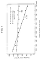
- the discharge rate changes according to the powder paint level in the tank as shown by line a in Fig. 1.
- an injector is directly attached to the side or top of the paint tank containing powder paint.
- the injector is coupled to the painting gun through a hose.
- the powder paint in the paint tank is drawn out by the injector together with air.
- the air is used to send the powder paint to the painting gun.
- the discharge rate through the painting gun is determined by the air pressure and air amount of the injector. In order to provide a painted surface having a uniform film thickness, the discharge rate through the painting gun has to be uniform.
- a third object of the present invention is to provide a powder paint supply device which assures a uniform discharge rate of powder paint through the painting gun.
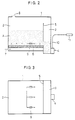
- this invention provides an improved fluid type powder paint tank. Its embodiments are described with reference to Figs. 2 - 6.
- the fluidized type powder paint tank 1 has a fluidizing chamber 2 for moving powder paint A as a fluid and a storage chamber 3 for holding the powder paint A drawn from the fluidizing chamber 2 in a stationary state.
- a discharge device 4 is attached to the storage chamber 3 to discharge the powder paint A therefrom.
- the powder paint tank of the embodiment shown in Figs. 2 and 3 is provided with a partitioning wall 5 on the righthand side thereof, defining the fluidizing chamber 2 on the left of the wall 5 and the storage chamber 3 on its right.
- a porous plate 6 is provided slightly spaced apart from the bottom thereof. Compressed air 7 is fed under the porous plate 6. An air vent 8 is provided at the top of the fluidizing chamber 2.
- the fluidizing chamber 2 and the storage chamber 3 communicate with each other at the lower part of the fluidizing chamber 2.
- An air purge nozzle 9 is provided in the fluidizing chamber 2 at the lower part thereof to discharge the powder paint A in the fluidizing chamber 2 into the storage chamber 3 by intermittently feeding air toward the storage chamber 3.
- the powder paint A in the fluidizing chamber 2 may be discharged into the storage chamber 3 with a scraper which moves on and along the porous plate 6 toward the storage chamber 3,
- the bottom of the storage chamber 3 is at a level lower than the bottoms of the porous plate 6 and the tank 1.
- An injector as the discharge device 4 is mounted at the lower part of the storage chamber 3.
- a painting gun 11 is connected to the injector 4 through a powder supply hose 10.
- the embodiment shown in Fig. 4 has the same structure as the embodiment shown in Figs. 2 and 3 except the discharge device 4.
- the discharge device 4 in this embodiment has the following structure. Namely, a screw 13 rotated by a motor 12 is mounted in the bottom of the storage chamber 3. A discharge port 14 is formed in the side of the storage chamber 3 at the front end of the screw 13. Beside the discharge port 14, there is provided a cylindrical flow straightener 15 having a drop hole in the bottom thereof. Beside the flow straightener 15, a spring housing 16 is provided. A lid plate 18 is secured to the end of the screw 13 and pressed against the discharge port 14 by a spring 17 housed in the spring housing 16.
- the powder A at the bottom of the storage chamber 3 is pushed out toward the discharge port 14.
- the spring 17 is compressed and the lid plate 18 is opened by this pushing force, so that the powder is blown out through a gap between the lid plate 18 and the discharge port 14.
- the powder thus blown out hits and moves along the inner peripheral surface of the flow straightener 15 and is discharged in uniform amounts into a hopper 19 provided thereunder.
- An injector 20 is mounted to the bottom of the hopper 19. The powder is fed from the injector 20 into the painting gun 11 through a powder supply hose 10.
- a porous plate 6 is provided over the bottom of the tank 1 so as to cover the entire bottom surface.
- a partitioning wall 5 is provided to divide the space over the porous plate 6 into the fluidizing chamber 2 and the storage chamber 3.
- a shield plate 21 is provided on the porous plate 6 at its portion located in the storage chamber 3 near its bottom to prevent the air supply from the porous plate into the storage chamber 3.
- the embodiment shown in Fig. 4 is the same in structure as the embodiment shown in Fig. 1.
- the tank 1 of the embodiment shown in Fig. 6 has the same structure as that of the embodiment shown in Fig. 5.
- the discharge device 4 has the same structure as that of the embodiment shown in Fig. 4.
- the motor 12 for the screw 13 is mounted on the tip of the screw.
- the powder paint tank according to this invention can discharge the paint in constant amounts irrespective of the paint level in the tank.
- the thickness of paint can be kept constant.
- this invention provides an improved means for drawing out a powder paint. Its embodiment is described with reference to Figs. 7 and 8.
- a porous plate 32 is mounted in the tank at the bottom thereof. Compressed air is supplied under the porous plate 32 to move the powder paint in the tank.
- An outlet port 33 is formed in the side wall of the tank 31 at its lower part.
- An outlet pipe 34 is connected to the outlet port 33.
- a pinch valve 35 is connected to the bottom end of the outlet pipe 34. It comprises a shrinkable tube 36 made of rubber or the like and a casing 37 covering the tube 36. An air supply pipe 38 is connected to the casing 37. By supplying air through the air supply pipe 38 into between the inner wall of the casing 37 and the outer wall of the tube 36, the tube shrinks, thus closing the flow path. When the supply of air is stopped, the tube 36 expands, opening the flow path.
- the air supply pipe 38 has a branch pipe 39 connected to the outlet pipe 34 above the pinch valve 35.
- a check valve 40 to prohibit the fluid flow from the outlet pipe 39 toward the air supply pipe 38.
- the powder paint drawn out through the pinch valve 35 is supplied into the painting gun through a hopper 41.
- a powder paint tank 51 is of a fluidized type.
- this type of powder paint tank in order to improve the dispersibility of the powder paint, air is uniformly blown into the powder layer through a porous plate 52 provided at the bottom to fluidize the powder paint.
- a discharge pipe 54 provided with a pinch valve 53.
- the powder paint in the powder paint tank 51 can be discharged downward by free fall.
- the discharge pipe 54 is connected to the top of a hopper 55, which is provided with a level switch 56 for detecting the level of the powder paint stored in the hopper.
- the hopper 55 is provided with a lid 57 on top thereof.
- the lid 57 is provided with an air vent to expel excess air present in the powder paint fed into the hopper 55.
- the amount of the paint in the hopper 55 per unit volume will be uniform.
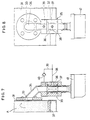
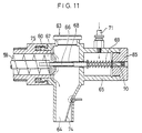
- a support shaft 66 extending through the flow straightener 63 and the spring housing 65.
- a lid plate 67 is slidably fitted on the support shaft 66 at its portion located in the flow straightener 63 to close the end face of the discharge port 60.
- a pipe 68 is fitted on the support shaft 66 at its portion behind the lid plate 67.
- the pipe 68 has its tip end protruding into the spring housing 65 and its rear end secured to the back of the lid plate 67.
- a spring 69 is fitted on the support shaft 66 at its portion located in the spring housing 65. The lid plate 67 is pressed by the spring 69 through the pipe 68 against the discharge port 60.
- a support plate 70 for supporting the end of the spring 69 is mounted on the tip of the support shaft 66 so as to be movable relative to the support shaft. In order to adjust the force of the spring 69, the support plate 70 is moved by turning a threaded cap 85 provided at the end of the spring housing 65.
- An air inlet pipe 71 is connected to the spring housing 65. Its interior is kept at positive pressure, thus preventing powder paint from flowing into the spring housing 65.
- An agitating rotary wheel 72 is mounted in the hopper 55 at its lower part, It is provided around its periphery with protrusions 73 at predetermined intervals so that they can fit into the pitch gaps defined by the screw 59.
- the agitating rotary wheel 72 is adapted to rotate as the screw 59 turns.
- the powder paint forming the lower layer in the hopper 55 is pushed out toward the discharge port 60.
- the spring 69 is compressed and the lid plate 67 is opened, so that the powder paint pushed out through a gap between the lid plate 67 and the discharge port 60 will blow out.
- the powder paint blown out of the lid plate 67 and the discharge port 60 then hits the inner surface of the flow straightener 63 and is discharged at a constant rate through the drop port 64 while moving along the inner peripheral surface of the flow straightener 63.
- a chute 76 (Fig. 9) is provided under the drop port 64 of the flow straightener 63. To an outlet 77 of the chute 76 is coupled an inlet port 79 of an injector 78. A hose 81 is coupled to a discharge port 80 of the injector 78. A painting gun 82 is coupled to the tip of the hose 81. A sensor 83 is provided in the chute 76 which is adapted to detect a predetermined amount of powder paint. The amount of air to be fed into the injector 78 will be sufficient if the powder paint supplied in regular amounts to the inlet port 79 of the injector 78 from the screw feeder 58 can be discharged through the hose 81 and the painting gun 82. An electropneumatic regulator may be provided in the air circuit to electrically control the air supply amount to a minimum value corresponding to the amount of discharge.
- a sieve may be provided in the drop port 64 of the screw feeder 58 to improve the dispersibility of the powder paint.
- numeral 84 designates a height-adjustable base.
- the pinch valve 53 is opened and closed at predetermined intervals so that the powder paint in the paint tank 51 will accumulate in the hopper 55 in predetermined amounts.
- the amount is detected by the level switch 56. Any abnormality of powder supply can be detected by electrically monitoring the opening and closing of the pinch valve 53 and the time taken until the powder reaches the level switch 56.
- the time taken until the powder paint reaches the level switch 56 after opening the pinch valve 53 will become shorter than a monitoring cycle time. If the powder supply line from the paint tank 51 to the hopper 55 should fail, the time taken until the powder paint reaches the level switch 56 will become longer than the monitoring cycle time. If the time is out of the range of monitoring cycle time, the line is stopped on the assumption that it has failed.
- any excess air in the powder paint supplied into the hopper 55 is spontaneously expelled while being accumulated.
- the powder paint in the hopper 55 is fed out at a constant rate through the discharge port 60 by the screw feeder 58.
- the spring 69 is compressed and the lid plate 67 is opened, so that the powder paint pushed out through a gap between the lid plate 67 and the discharge port 60 will blow out.
- the powder paint blown out of the lid plate 67 and the discharge port 60 then hits the inner surface of the flow straightener 63 and is supplied at a constant rate into the inlet port 79 of the injector 78 through the drop port 64 and the chute 76.
- the powder paint supplied into the injector 78 is then supplied by air through the hose 81 and discharged through the painting gun 82.
- the powder paint will flow over the inlet port 79 of the injector 78 and keep at the outlet 77 of the chute 76.
- the accumulation of the powder paint at the outlet of the chute 76 is detected by the sensor 3. This makes it possible to stop the painting line when abnormality is detected. Thus, production of defective articles can be minimized.
- the amount of paint discharged through the painting gun can be kept uniform even if there is a slight pressure loss in the hose of the painting gun.
- the discharge rate through the painting gun can be set to any desired value.
Landscapes
- Engineering & Computer Science (AREA)
- Mechanical Engineering (AREA)
- Chemical & Material Sciences (AREA)
- Combustion & Propulsion (AREA)
- Organic Chemistry (AREA)
- Chemical Kinetics & Catalysis (AREA)
- Physics & Mathematics (AREA)
- Fluid Mechanics (AREA)
- General Physics & Mathematics (AREA)
- Electrostatic Spraying Apparatus (AREA)
- Nozzles (AREA)
- Coating Apparatus (AREA)
Applications Claiming Priority (13)
| Application Number | Priority Date | Filing Date | Title |
|---|---|---|---|
| JP40805390 | 1990-12-27 | ||
| JP408025/90 | 1990-12-27 | ||
| JP2408025A JP2831476B2 (ja) | 1990-12-27 | 1990-12-27 | 静電粉体塗装装置における粉体塗料供給装置 |
| JP2408053A JP2886347B2 (ja) | 1990-12-27 | 1990-12-27 | 静電粉体塗装装置における塗料供給装置 |
| JP40802590 | 1990-12-27 | ||
| JP408053/90 | 1990-12-27 | ||
| JP145802/91 | 1991-06-18 | ||
| JP3145802A JP2641811B2 (ja) | 1991-06-18 | 1991-06-18 | 流動式粉体塗料タンク |
| JP14580291 | 1991-06-18 | ||
| JP14737891 | 1991-06-19 | ||
| JP14737891A JP2573435B2 (ja) | 1991-06-19 | 1991-06-19 | 粉体塗料供給装置 |
| JP147378/91 | 1991-06-19 | ||
| EP91311877A EP0496165B1 (de) | 1990-12-27 | 1991-12-20 | Vorrichtung zur Förderung von Pulverfarben |
Related Parent Applications (2)
| Application Number | Title | Priority Date | Filing Date |
|---|---|---|---|
| EP91311877.4 Division | 1991-12-20 | ||
| EP91311877A Division EP0496165B1 (de) | 1990-12-27 | 1991-12-20 | Vorrichtung zur Förderung von Pulverfarben |
Publications (2)
| Publication Number | Publication Date |
|---|---|
| EP0695583A1 true EP0695583A1 (de) | 1996-02-07 |
| EP0695583B1 EP0695583B1 (de) | 2000-03-15 |
Family
ID=27472665
Family Applications (2)
| Application Number | Title | Priority Date | Filing Date |
|---|---|---|---|
| EP95112383A Expired - Lifetime EP0695583B1 (de) | 1990-12-27 | 1991-12-20 | Vorrichtung zur Zuführung von Pulverfarben |
| EP91311877A Expired - Lifetime EP0496165B1 (de) | 1990-12-27 | 1991-12-20 | Vorrichtung zur Förderung von Pulverfarben |
Family Applications After (1)
| Application Number | Title | Priority Date | Filing Date |
|---|---|---|---|
| EP91311877A Expired - Lifetime EP0496165B1 (de) | 1990-12-27 | 1991-12-20 | Vorrichtung zur Förderung von Pulverfarben |
Country Status (4)
| Country | Link |
|---|---|
| US (3) | US5240185A (de) |
| EP (2) | EP0695583B1 (de) |
| DE (2) | DE69132062T2 (de) |
| ES (1) | ES2083537T3 (de) |
Cited By (2)
| Publication number | Priority date | Publication date | Assignee | Title |
|---|---|---|---|---|
| EP0832695A3 (de) * | 1996-09-27 | 1998-12-23 | ITW Limited | Elektrostatisches Aromatisierungssystem |
| ITRA20080051A1 (it) * | 2008-12-19 | 2010-06-20 | Ragazzini S R L | Impianto di trasporto |
Families Citing this family (44)
| Publication number | Priority date | Publication date | Assignee | Title |
|---|---|---|---|---|
| US5654042A (en) * | 1992-12-17 | 1997-08-05 | Nordson Corporation | Powder coating system for difficult to handle powders |
| US5743958A (en) | 1993-05-25 | 1998-04-28 | Nordson Corporation | Vehicle powder coating system |
| EP1070547B1 (de) * | 1993-05-25 | 2008-01-09 | Nordson Corporation | Pulverbeschichtungssystem |
| JPH07172575A (ja) * | 1993-12-17 | 1995-07-11 | Nordson Kk | 粉粒体の供給搬送方法 |
| FR2720664B1 (fr) * | 1994-06-01 | 1996-08-30 | Sames Sa | Dispositif de projection de produit de revêtement pulvérulent. |
| DE4423254C2 (de) * | 1994-07-02 | 1998-11-05 | Gema Volstatic Ag | Pneumatische Fördervorrichtung für Pulver, insbesondere Beschichtungspulver |
| US5713494A (en) * | 1994-08-05 | 1998-02-03 | Matsuo Sangyo Co., Ltd. | Powder feeding device |
| US5752788A (en) * | 1994-11-30 | 1998-05-19 | Nordson Corporation | System and method of pumping a constant volume of powder |
| US5636799A (en) * | 1995-01-13 | 1997-06-10 | Clark Equipment Company | Frame mounted isolated motor driven electrostatic spray system |
| US5568885A (en) * | 1995-03-13 | 1996-10-29 | Abc Techcorp | Agitator for liquid pump |
| US5768800A (en) * | 1995-06-08 | 1998-06-23 | Matsuo Sangyo Co. Ltd. | Powder feed mechanism |
| US5722802A (en) * | 1995-06-09 | 1998-03-03 | Low Emission Paint Consortium | Powder delivery apparatus |
| US5839668A (en) * | 1996-01-29 | 1998-11-24 | Accudyne Corporation | Micro-spacer metering apparatus employing multi-cavity disc and pneumatic ejection head for flat panel display assembly |
| JP3386326B2 (ja) * | 1996-12-26 | 2003-03-17 | 株式会社日清製粉グループ本社 | 粉体塗装用粉体塗料供給機 |
| US5853126A (en) * | 1997-02-05 | 1998-12-29 | Illinois Tool Works, Inc. | Quick disconnect for powder coating apparatus |
| US6328224B1 (en) | 1997-02-05 | 2001-12-11 | Illinois Tool Works Inc. | Replaceable liner for powder coating apparatus |
| EP0857515A3 (de) | 1997-02-05 | 1998-09-16 | Illinois Tool Works Inc. | Abluftstrom einer Turbine einer Pulverbeschichtungsvorrichtung |
| JP3697066B2 (ja) * | 1997-07-31 | 2005-09-21 | キヤノン株式会社 | トナー補給容器、及び、電子写真画像形成装置 |
| US6056483A (en) * | 1997-09-10 | 2000-05-02 | Nihon Parkerizing Co., Ltd. | Powder coating material feeding apparatus |
| IL122230A (en) | 1997-11-17 | 2003-12-10 | Milsys Ltd | Biometric system and techniques suitable therefor |
| US5996855A (en) * | 1998-02-27 | 1999-12-07 | Material Sciences Corporation | Cross-feed auger and method |
| US6073818A (en) * | 1998-06-19 | 2000-06-13 | Genzyme Transgenics Corporation | Apparatus for controlled delivery of powdered solid materials |
| US6299387B1 (en) * | 1998-12-23 | 2001-10-09 | Rolf Andersson | Method for evacuating a storage silo for bulk goods, E.G. cereal grain, and an evacuation conveyor thereto |
| US6399912B1 (en) | 2000-04-25 | 2002-06-04 | Illinois Tool Works Inc. | Method and apparatus for submerged arc welding |
| IL145464A0 (en) * | 2001-09-16 | 2002-06-30 | Pc Composites Ltd | Electrostatic coater and method for forming prepregs therewith |
| DE10317919B4 (de) * | 2003-04-17 | 2005-12-01 | Fraunhofer-Gesellschaft zur Förderung der angewandten Forschung e.V. | Vorrichtung und Verfahren zur Beschichtung eines Substrates mit einem flüssigen oder partikulären Beschichtungsmaterial |
| US6810929B1 (en) * | 2003-06-12 | 2004-11-02 | Ppg Industries Ohio, Inc. | Transportable container for fluidizable material and method |
| EP1591055B9 (de) * | 2004-04-19 | 2009-08-26 | Electrolux Home Products Corporation N.V. | Automatische Dosiervorrichtung mit Antriebsfreilaufvorrichtung |
| US7500806B2 (en) * | 2004-06-30 | 2009-03-10 | Barnard Construction Company, Inc. | Method and apparatus for constructing filter zones in earthfill dams |
| EP1762302A3 (de) * | 2005-09-09 | 2009-07-08 | Sulzer Metco AG (Switzerland) | Pulverversorgungssystem |
| US7891315B2 (en) * | 2005-09-09 | 2011-02-22 | Sulzer Metco Ag | Powder supply system |
| DE102006057898B4 (de) | 2006-12-08 | 2011-06-01 | Eisenmann Anlagenbau Gmbh & Co. Kg | Vorrichtung zum Fördern fluidisierbarer Medien |
| US20080152437A1 (en) * | 2006-12-26 | 2008-06-26 | Illinois Tool Works Inc. | Pulverulent material transport |
| US20080205189A1 (en) | 2007-02-27 | 2008-08-28 | Illinois Tool Works Inc. | Dense phase pump for pulverulent material |
| US8371517B2 (en) | 2007-06-29 | 2013-02-12 | Illinois Tool Works Inc. | Powder gun deflector |
| WO2012098592A1 (ja) * | 2011-01-20 | 2012-07-26 | 大和製衡株式会社 | 計量装置 |
| NO338642B1 (no) * | 2014-09-12 | 2016-09-26 | Norsk Hydro As | Anordning og fremgangsmåte for mating av doser av fluidiserbare materialer |
| JP6459595B2 (ja) * | 2015-02-16 | 2019-01-30 | セイコーエプソン株式会社 | シート製造装置 |
| CN107008624B (zh) * | 2017-04-27 | 2023-02-24 | 新乡市振英机械设备有限公司 | 一种涂布机供料装置 |
| US9845206B1 (en) * | 2017-05-01 | 2017-12-19 | Viacheslav E. Baranovski | Method and apparatus for direct injection of powder material into a powder hose |
| CA3112530C (en) * | 2018-09-18 | 2023-08-29 | Flsmidth A/S | Apparatus to convey pulverized material |
| CN112206719A (zh) * | 2020-10-22 | 2021-01-12 | 宝钛华神钛业有限公司 | 一种用于四氯化锆回收的匀速加料装置 |
| CN112427159B (zh) * | 2020-11-18 | 2021-06-25 | 湖南连心科技有限公司 | 一种用于粉末涂料静电喷涂的供粉装置 |
| JP7208665B1 (ja) * | 2021-08-02 | 2023-01-19 | 株式会社豊製作所 | 粉体供給装置 |
Citations (11)
| Publication number | Priority date | Publication date | Assignee | Title |
|---|---|---|---|---|
| GB637472A (en) * | 1946-10-17 | 1950-05-17 | Fuller Co | Improvements in method and apparatus for handling pulverulent materials |
| FR2024760A1 (de) * | 1968-07-15 | 1970-09-04 | Controsion Electrostatic Ltd | |
| FR2215375A1 (de) * | 1973-01-25 | 1974-08-23 | Carrier | |
| EP0098340A1 (de) * | 1982-07-02 | 1984-01-18 | Claudius Peters Aktiengesellschaft | Schneckenpumpe mit an beiden Enden gelagerter Schnecke |
| FR2566875A1 (fr) * | 1984-06-29 | 1986-01-03 | Cle Groupe Technip | Procede et dispositif pour limiter les dangers d'obstruction dans des conduits comportant des zones a risques d'obstruction, notamment des coudes, rebroussements de conduits ou analogues |
| EP0239331A2 (de) * | 1986-03-25 | 1987-09-30 | Onoda Cement Company, Ltd. | Gerät zur automatischen Pulverzufuhr |
| WO1988004202A1 (en) * | 1986-12-08 | 1988-06-16 | Nordson Corporation | Powder spraying system |
| WO1988004203A2 (en) * | 1986-12-08 | 1988-06-16 | Nordson Corporation | Powder feeder apparatus |
| DE3813551A1 (de) * | 1988-03-17 | 1989-09-28 | Brieden Karl Bau Beteiligung | Vorrichtung zur steilfoerderung von baustoff im untertagebetrieb |
| WO1990003848A1 (en) * | 1988-10-11 | 1990-04-19 | Willmet, Inc. | Method of and apparatus for flame spraying refractory material |
| WO1994027731A1 (fr) * | 1993-05-24 | 1994-12-08 | Sames S.A. | Procede et dispositif d'alimentation d'une installation de projection de produit pulverulent |
Family Cites Families (15)
| Publication number | Priority date | Publication date | Assignee | Title |
|---|---|---|---|---|
| US2957493A (en) * | 1960-10-25 | Nilsen | ||
| US1971852A (en) * | 1931-06-03 | 1934-08-28 | Firm G Polysius Ag | Process for stirring up farinaceous materials in receptacles of any kind by compressed air, compressed gas, or the like |
| US2167416A (en) * | 1937-07-21 | 1939-07-25 | Adolph G Carlson | Feeder for pulverized materials |
| GB772125A (en) * | 1955-10-06 | 1957-04-10 | Smidth & Co As F L | Improvements relating to methods of and apparatus for packing powdered or granular material into valve bags |
| BE600113A (de) * | 1960-02-12 | 1900-01-01 | ||
| US3149884A (en) * | 1963-01-07 | 1964-09-22 | Magnet Cove Barium Corp | Pneumatic conveyer |
| FR1434276A (fr) * | 1965-02-23 | 1966-04-08 | Socam | Dispositif d'extraction pour produits pulvérulents |
| NO120420B (de) * | 1967-04-24 | 1970-10-19 | Alfa Laval Ab | |
| US3995771A (en) * | 1975-05-19 | 1976-12-07 | Kaiser Aluminum & Chemical Corporation | Feeding device for particulate matter |
| US4170074A (en) * | 1976-12-06 | 1979-10-09 | Owens-Illinois, Inc. | Powder dryer including fluidized bed aspirator |
| US4453865A (en) * | 1982-07-21 | 1984-06-12 | Stone & Webster Engineering Corp. | Automatic pressure sensitive regulation assembly |
| US4502820A (en) * | 1982-08-16 | 1985-03-05 | Denka Engineering Kabushiki Kaisha | High-pressure conveyor for powdery and granular materials |
| FR2567234B1 (fr) * | 1984-07-04 | 1986-12-12 | Charbonnages De France | Vanne pour repartition pneumatique de matiere fluidisable |
| NO162774C (no) * | 1987-10-09 | 1990-02-14 | Norsk Hydro As | Pneumatisk doseringsapparat. |
| US5175942A (en) * | 1991-07-19 | 1993-01-05 | Gte Products Corporation | Method for fluidized bed discharge |
-
1991
- 1991-12-20 ES ES91311877T patent/ES2083537T3/es not_active Expired - Lifetime
- 1991-12-20 DE DE69132062T patent/DE69132062T2/de not_active Expired - Fee Related
- 1991-12-20 EP EP95112383A patent/EP0695583B1/de not_active Expired - Lifetime
- 1991-12-20 DE DE69117275T patent/DE69117275T2/de not_active Expired - Fee Related
- 1991-12-20 EP EP91311877A patent/EP0496165B1/de not_active Expired - Lifetime
- 1991-12-24 US US07/813,013 patent/US5240185A/en not_active Expired - Lifetime
-
1993
- 1993-02-05 US US08/014,467 patent/US5335828A/en not_active Expired - Lifetime
- 1993-02-05 US US08/014,466 patent/US5323547A/en not_active Expired - Lifetime
Patent Citations (11)
| Publication number | Priority date | Publication date | Assignee | Title |
|---|---|---|---|---|
| GB637472A (en) * | 1946-10-17 | 1950-05-17 | Fuller Co | Improvements in method and apparatus for handling pulverulent materials |
| FR2024760A1 (de) * | 1968-07-15 | 1970-09-04 | Controsion Electrostatic Ltd | |
| FR2215375A1 (de) * | 1973-01-25 | 1974-08-23 | Carrier | |
| EP0098340A1 (de) * | 1982-07-02 | 1984-01-18 | Claudius Peters Aktiengesellschaft | Schneckenpumpe mit an beiden Enden gelagerter Schnecke |
| FR2566875A1 (fr) * | 1984-06-29 | 1986-01-03 | Cle Groupe Technip | Procede et dispositif pour limiter les dangers d'obstruction dans des conduits comportant des zones a risques d'obstruction, notamment des coudes, rebroussements de conduits ou analogues |
| EP0239331A2 (de) * | 1986-03-25 | 1987-09-30 | Onoda Cement Company, Ltd. | Gerät zur automatischen Pulverzufuhr |
| WO1988004202A1 (en) * | 1986-12-08 | 1988-06-16 | Nordson Corporation | Powder spraying system |
| WO1988004203A2 (en) * | 1986-12-08 | 1988-06-16 | Nordson Corporation | Powder feeder apparatus |
| DE3813551A1 (de) * | 1988-03-17 | 1989-09-28 | Brieden Karl Bau Beteiligung | Vorrichtung zur steilfoerderung von baustoff im untertagebetrieb |
| WO1990003848A1 (en) * | 1988-10-11 | 1990-04-19 | Willmet, Inc. | Method of and apparatus for flame spraying refractory material |
| WO1994027731A1 (fr) * | 1993-05-24 | 1994-12-08 | Sames S.A. | Procede et dispositif d'alimentation d'une installation de projection de produit pulverulent |
Non-Patent Citations (1)
| Title |
|---|
| PATENT ABSTRACTS OF JAPAN vol. 7, no. 171 (C - 178)<1316> 28 July 1983 (1983-07-28) * |
Cited By (3)
| Publication number | Priority date | Publication date | Assignee | Title |
|---|---|---|---|---|
| EP0832695A3 (de) * | 1996-09-27 | 1998-12-23 | ITW Limited | Elektrostatisches Aromatisierungssystem |
| ITRA20080051A1 (it) * | 2008-12-19 | 2010-06-20 | Ragazzini S R L | Impianto di trasporto |
| WO2010070438A1 (en) * | 2008-12-19 | 2010-06-24 | Ragazzini S.R.L. | Transport plant |
Also Published As
| Publication number | Publication date |
|---|---|
| US5323547A (en) | 1994-06-28 |
| DE69132062D1 (de) | 2000-04-20 |
| ES2083537T3 (es) | 1996-04-16 |
| US5240185A (en) | 1993-08-31 |
| EP0496165B1 (de) | 1996-02-21 |
| EP0496165A3 (en) | 1992-12-16 |
| DE69117275T2 (de) | 1996-07-11 |
| DE69117275D1 (de) | 1996-03-28 |
| EP0496165A2 (de) | 1992-07-29 |
| EP0695583B1 (de) | 2000-03-15 |
| DE69132062T2 (de) | 2000-09-07 |
| US5335828A (en) | 1994-08-09 |
Similar Documents
| Publication | Publication Date | Title |
|---|---|---|
| EP0496165A2 (de) | Vorrichtung zur Förderung von Pulverfarben | |
| US5340241A (en) | Device for metering and entraining a product into a gas stream | |
| US4812086A (en) | Particulate material loader | |
| US20100255975A1 (en) | Powder recovering device or powder spray coating apparatus | |
| US5713494A (en) | Powder feeding device | |
| JPH03138217A (ja) | ニユーマチツク式のサクシヨンコンベヤ装置 | |
| US20080184793A1 (en) | Powder level sensor unit for spray coating powder | |
| US5573149A (en) | Storetank for powder supply and powder coating equipment with storetank for powder supply | |
| KR101578553B1 (ko) | 미세분말 공급장치 | |
| US3917126A (en) | Feeding device | |
| JPS5926461B2 (ja) | 流動性加工材料を加工機械へ自動的に供給する装置 | |
| US3795348A (en) | Device for delivering particulate material | |
| US12429371B2 (en) | Weighing and transporting device and method for transporting and detecting mass flow rates of bulk materials | |
| US4764057A (en) | Device for producing a solid aerosol | |
| WO2003084672A1 (fr) | Dispositif d'alimentation en poudre | |
| WO1997012760A1 (en) | Powder spray systems and methods for their use | |
| JP3565917B2 (ja) | 粉体の定量供給装置 | |
| US10589302B2 (en) | Powder container for a powder coating station | |
| JPH04225855A (ja) | 静電粉体塗装装置における塗料供給装置 | |
| JP2641811B2 (ja) | 流動式粉体塗料タンク | |
| US3309146A (en) | Method of transporting material and device therefor | |
| JP2902218B2 (ja) | 粉体塗料の搬送装置 | |
| JPH04223913A (ja) | 静電粉体塗装装置における粉体塗料供給装置 | |
| JP2008100212A (ja) | プリコート投入装置および方法 | |
| JP3396707B2 (ja) | 粉体塗料の定量供給装置 |
Legal Events
| Date | Code | Title | Description |
|---|---|---|---|
| PUAI | Public reference made under article 153(3) epc to a published international application that has entered the european phase |
Free format text: ORIGINAL CODE: 0009012 |
|
| AC | Divisional application: reference to earlier application |
Ref document number: 496165 Country of ref document: EP |
|
| AK | Designated contracting states |
Kind code of ref document: A1 Designated state(s): CH DE ES FR GB IT LI NL SE |
|
| 17P | Request for examination filed |
Effective date: 19960417 |
|
| 17Q | First examination report despatched |
Effective date: 19980414 |
|
| GRAG | Despatch of communication of intention to grant |
Free format text: ORIGINAL CODE: EPIDOS AGRA |
|
| GRAG | Despatch of communication of intention to grant |
Free format text: ORIGINAL CODE: EPIDOS AGRA |
|
| GRAH | Despatch of communication of intention to grant a patent |
Free format text: ORIGINAL CODE: EPIDOS IGRA |
|
| GRAH | Despatch of communication of intention to grant a patent |
Free format text: ORIGINAL CODE: EPIDOS IGRA |
|
| GRAA | (expected) grant |
Free format text: ORIGINAL CODE: 0009210 |
|
| AC | Divisional application: reference to earlier application |
Ref document number: 496165 Country of ref document: EP |
|
| AK | Designated contracting states |
Kind code of ref document: B1 Designated state(s): CH DE ES FR GB IT LI NL SE |
|
| PG25 | Lapsed in a contracting state [announced via postgrant information from national office to epo] |
Ref country code: SE Free format text: THE PATENT HAS BEEN ANNULLED BY A DECISION OF A NATIONAL AUTHORITY Effective date: 20000315 Ref country code: NL Free format text: LAPSE BECAUSE OF FAILURE TO SUBMIT A TRANSLATION OF THE DESCRIPTION OR TO PAY THE FEE WITHIN THE PRESCRIBED TIME-LIMIT Effective date: 20000315 Ref country code: ES Free format text: THE PATENT HAS BEEN ANNULLED BY A DECISION OF A NATIONAL AUTHORITY Effective date: 20000315 |
|
| REG | Reference to a national code |
Ref country code: CH Ref legal event code: NV Representative=s name: KIRKER & CIE SA Ref country code: CH Ref legal event code: EP |
|
| REF | Corresponds to: |
Ref document number: 69132062 Country of ref document: DE Date of ref document: 20000420 |
|
| ET | Fr: translation filed | ||
| ITF | It: translation for a ep patent filed | ||
| NLV1 | Nl: lapsed or annulled due to failure to fulfill the requirements of art. 29p and 29m of the patents act | ||
| PLBE | No opposition filed within time limit |
Free format text: ORIGINAL CODE: 0009261 |
|
| STAA | Information on the status of an ep patent application or granted ep patent |
Free format text: STATUS: NO OPPOSITION FILED WITHIN TIME LIMIT |
|
| 26N | No opposition filed | ||
| REG | Reference to a national code |
Ref country code: GB Ref legal event code: IF02 |
|
| PGFP | Annual fee paid to national office [announced via postgrant information from national office to epo] |
Ref country code: FR Payment date: 20051208 Year of fee payment: 15 |
|
| PGFP | Annual fee paid to national office [announced via postgrant information from national office to epo] |
Ref country code: GB Payment date: 20051214 Year of fee payment: 15 |
|
| PGFP | Annual fee paid to national office [announced via postgrant information from national office to epo] |
Ref country code: DE Payment date: 20051215 Year of fee payment: 15 |
|
| PGFP | Annual fee paid to national office [announced via postgrant information from national office to epo] |
Ref country code: CH Payment date: 20051229 Year of fee payment: 15 |
|
| PG25 | Lapsed in a contracting state [announced via postgrant information from national office to epo] |
Ref country code: LI Free format text: LAPSE BECAUSE OF NON-PAYMENT OF DUE FEES Effective date: 20061231 Ref country code: CH Free format text: LAPSE BECAUSE OF NON-PAYMENT OF DUE FEES Effective date: 20061231 |
|
| PGFP | Annual fee paid to national office [announced via postgrant information from national office to epo] |
Ref country code: IT Payment date: 20061231 Year of fee payment: 16 |
|
| PG25 | Lapsed in a contracting state [announced via postgrant information from national office to epo] |
Ref country code: DE Free format text: LAPSE BECAUSE OF NON-PAYMENT OF DUE FEES Effective date: 20070703 |
|
| REG | Reference to a national code |
Ref country code: CH Ref legal event code: PL |
|
| GBPC | Gb: european patent ceased through non-payment of renewal fee |
Effective date: 20061220 |
|
| REG | Reference to a national code |
Ref country code: FR Ref legal event code: ST Effective date: 20070831 |
|
| PG25 | Lapsed in a contracting state [announced via postgrant information from national office to epo] |
Ref country code: GB Free format text: LAPSE BECAUSE OF NON-PAYMENT OF DUE FEES Effective date: 20061220 |
|
| PG25 | Lapsed in a contracting state [announced via postgrant information from national office to epo] |
Ref country code: FR Free format text: LAPSE BECAUSE OF NON-PAYMENT OF DUE FEES Effective date: 20070102 |
|
| PG25 | Lapsed in a contracting state [announced via postgrant information from national office to epo] |
Ref country code: IT Free format text: LAPSE BECAUSE OF NON-PAYMENT OF DUE FEES Effective date: 20071220 |