EP0695687A2 - Dispositif pour cercler des marchandises emballées - Google Patents
Dispositif pour cercler des marchandises emballées Download PDFInfo
- Publication number
- EP0695687A2 EP0695687A2 EP95107013A EP95107013A EP0695687A2 EP 0695687 A2 EP0695687 A2 EP 0695687A2 EP 95107013 A EP95107013 A EP 95107013A EP 95107013 A EP95107013 A EP 95107013A EP 0695687 A2 EP0695687 A2 EP 0695687A2
- Authority
- EP
- European Patent Office
- Prior art keywords
- strapping
- roller
- rollers
- guide frame
- strapping means
- Prior art date
- Legal status (The legal status is an assumption and is not a legal conclusion. Google has not performed a legal analysis and makes no representation as to the accuracy of the status listed.)
- Granted
Links
Images


Classifications
-
- B—PERFORMING OPERATIONS; TRANSPORTING
- B65—CONVEYING; PACKING; STORING; HANDLING THIN OR FILAMENTARY MATERIAL
- B65B—MACHINES, APPARATUS OR DEVICES FOR, OR METHODS OF, PACKAGING ARTICLES OR MATERIALS; UNPACKING
- B65B13/00—Bundling articles
- B65B13/18—Details of, or auxiliary devices used in, bundling machines or bundling tools
Definitions
- the invention relates to a device for strapping packaged goods according to the preamble of claim 1.
- the strapping means in modern machines almost exclusively weldable, thermoplastic plastic band, is shot in by means of a conveying device by means of a conveying device by means of a conveying device, by means of a conveying device, surrounding the packaged goods provided on a packing table or roller conveyor.
- these conveying devices generally consisting of roller-shaped pairs of rollers with at least one driven roller, with the strapping means held between the rollers being advanced.
- strapping tool guide frames generally have four rounded corner areas, which, however, can also offer particular resistance to the leading strapping end, even if they are carefully manufactured.
- the length of the strapping guide frame into which the strapping agent is loaded is must be 12 meters and more. It can be seen from this that the strapping of strapping material into a strapping guide frame can be problematic and can lead to considerable malfunctions.
- An intermediate conveyor has therefore been arranged in addition to the conveyor device assigned to the strapping agent supply or the sealing assembly, at a position within the strapping device guide frame at which the strapping device transported by the conveyor device has covered approximately 2/3 of its total circulation path.
- the two rollers of this additional conveyor consist of rollers, the axes of which are aligned transversely to the orbit of the strapping means and one roller behind and the other roller in front of the strapping means acts on the latter.
- the strap' is synonymous with the side of the strap pointing to the outside of the strap guide frame.
- the roller arranged here can rotate about a stationary axis, while the roller engaging on the inside of the strapping guide frame on the strapping means is provided in such a way that it is attached to a pivotable arm which can be pivoted out so far by means of a lifting magnet that the strapping means , if it comes free from the strapping guide frame to be tightened against the packaged goods ready, cannot get caught on the lifted roller.
- the smaller diameter sections form an insertion gap for the entry of the strapping between the two rollers, while the roughened sections are used for transporting the strapping.
- the ventilated, opposite second roller is a plastic roller with a smooth, slightly compressible jacket.
- the design, in particular of the metallic roller, is very complex and leads to an inhomogeneous transport of the strapping means, which manifests itself in a disadvantageous 'picking'.
- thermoplastic plastic belts with flat rectangular ones Cross-section as strapping means the risk that the strapping is compressed in a wedge shape, which manifests itself in that coercive forces are exerted on the belt section advanced by the additional conveyor, which can lead to an arcuate course of the leading strapping.
- the invention has for its object to provide a device of the type outlined in the preamble of claim 1, in which the additional conveyor is designed considerably simpler.
- Another aspect of the invention relates to a simplified possibility for venting at least one roller of the additional conveyor roller pair. Furthermore, the forces exerted by the rollers of the additional conveyor on the strapping means should be as low as possible, but in no case should they lead to malfunctions.
- the invention solves the problem in connection with the features of the preamble of claim 1 by its characterizing features. Thereafter, it is provided that the axes of the rollers laterally next to the orbit penetrate the plane defined by this and the at least one ventable roller can be swung out of the strapping movement path to the side against the action of a spring loading it against the strapping means and thus against the second roller .
- the axes of the rollers of the pair of additional conveyor rollers also lie transversely, in particular perpendicularly, in the additional conveyor of the invention. to the orbit of the strapping tool.
- they are not, as in the prior art, in planes parallel to the orbit, but penetrate the plane defined by the orbit or the strapping means.
- ventilation of at least one roll need not be pivoted around a large angular path of up to 90 o the role in question, but only a very small distance. This is because the roller does not engage the strapping means in front of and behind the orbit, but rather affects the orbit on the long sides of the strapping means.
- the release of the roll can be left to the strapping pull in a very simplified manner, if the strapping tool is tightened as a result of reversing the drive of the conveyor from the Strapping guide frame is released to be tightly tightened around the package.
- the pair of rollers now acting on both narrow sides and not on the front and the back of the strapping means is no longer able to disadvantageously deform the strapping means.
- the very small-area attack of the rollers on the long sides of the strapping means is completely sufficient to push the strapping means securely forward, but on the other hand surprisingly low forces are required, which therefore do not force the strapping means to buckle.
- the device designated overall by 10 in FIG. 1 serves for strapping particularly compressible packaged goods 11 such as corrugated cardboard layers or the like.
- First of all comprises a supply of strapping means 12 arranged close to the ground with strapping means 14 wound on a drum 13, in particular thermally weldable plastic strap.
- a cross member 16 is arranged vertically movable in the direction of the double arrow 17.
- the cross member 16 forms a press plate for compressing the packaged goods 11 or is a component thereof and stores on its upper side only a roughly indicated, known strapping closure assembly 18, which is used to form a closure overlapping strapping ends of the later around the packaged goods 11 taut strapping is used.
- a strapping means storage 19 is assigned to the closure assembly 18 and, like the closure assembly 18, is driven and guided in a uniform movement and thus in synchronism with the press plate 16.
- Both the posts 15, 15 'and the cross member 16 are assigned strapping guides 20 to 23 in the form of straight channels or channel sections of a known type. It is also known to form the portal-like strapping guide channel structure 20 to 23 into a self-contained strapping guide frame in that a lance or a bayonet 24 underneath the packaged goods 11 or the pallet on which it is stored, on the bottom contains a straight strapping guide channel.
- a strapping device infeed device 25 is provided directly behind the strapping stock 13, which, by means of strapping conveyor rollers 26, at least one of which is mechanically driven and the other is positively coupled to the strapping device feed, denotes the strapping device 14 into a strapping guide 28 Advance, which is arranged next to the post-like strapping guide 21 and parallel to it (behind it in the drawing).
- a strapping device 29 is arranged to be vertically movable, which has the task of transferring the strapping device 14 at the point at which the strapping device deflection 29 is located to a horizontally arranged strapping device transfer line 30, which it is used for Closure unit 18 continues. In the exemplary embodiment, this happens through the strapping material store 19. As soon as the leading free strapping end has reached a desired position in the closure assembly 18, the starting position for a first strapping of a packaged product 11 is reached.
- the packaged goods 11 to be strapped have been conveyed into the strapping zone perpendicular to the drawing plane.
- the strapping means 14 is again by means of a two conveyor rollers and the closure unit 18 assigned conveyor 32, namely counterclockwise with respect to FIG. 1 through the strapping guides 20, 21, 24, 22, and 23 and through the strapping means 33 to 36 located between them in the strapping path until the front end of the strapping means 14 again in the closure unit 18.
- the pressing plate 16, the closure assembly 18 and the belt store 19 lower down onto the top of the packaged goods 11, which is now compressed to a large extent depending on the nature and requirements.
- the drive of the strapping conveyor rollers 32 is reversed so that they pull back the strapping means 14 brought in by the strapping stock 12, while the other end of the strapping means is held on the closure assembly 18 by means of a clamp. Due to the strapping means retraction, the strapping means 14 is pulled out from the inside of all the strapping means guides which are designed for this purpose in a known manner, for example thus have flexible lips or flaps which open against spring action.
- the strapping guide frame 31 formed from the strapping guides 20-23 and the strapping deflections 33-36 represents a very long orbit for the strapping.
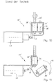
- the known additional conveyor 37 has two rollers 38' and 39 'designed as rollers.
- the rotatable roller 38 ' which is held in a fixed position, is assigned to the outside of the strapping guide frame 31 and by means of its not shown Motors can be driven in rotation.
- the second roller 39 ′ engages on the opposite side of the strapping means 14 and is consequently assigned to the inside of the strapping means guide frame 31.
- the axes 40 'and 41' of the two rollers 38 'and 39' are parallel to one another and parallel to the orbit defined by the longitudinal advance of the strapping means 14, namely on the one hand in front of and on the other hand behind the orbit. So that the strapping means 14 can be drawn in from its loading position within the strapping means guide frame 31 onto the circumference of the package, it is necessary to ventilate the roller 39 ′ which is arranged towards the inside of the guide frame.
- This ventable roller 39 ' is therefore mounted on a swivel arm 42 which can be swiveled out of the position according to FIG. 10 into the position according to FIG. 11 by means of a lifting magnet 43, which is indicated by the arrow denoted by 44.
- the roller 39 ' must be pivoted out so far that it is practically no longer in overlap with the roller 38' so that the strapping means 14 can snap towards the packaged goods 11 unhindered.
- the control of the solenoid 43 ' must be clocked depending on the machine cycle. Since, on the other hand, in the position shown in FIG. 10, the pair of rollers 38 '/ 39' must also be able to grasp the incoming end of the strapping means 24 in the nip, the particularly complex measures explained above on the roller 38 'were necessary.
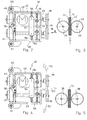
- the strip shown, which is flat in cross section, is contacted as strapping means 14 not by its broad sides, but rather by the narrow longitudinal edges 14 'of the rollers 38 and 39, which here are not designed as wide rollers but as flat, disc-shaped wheels are.
- the arrangement is such that the roller 38 is rotatably driven by a motor 45 and that on the end of the axle 40 remote from the roller 38, a pinion 46 is rotatably mounted, which meshes with a pinion 47, which at the associated end of the axis 41 sits, the other end of which carries the second roller 39.
- two receptacles 48 and 49 are used, each around an axis 50 and 51 parallel to the plane of the drawing and thus parallel to the longitudinal direction of the strapping means 14 or to the orbit of the strapping means 14 in the direction of the arrows 52 in FIG. 4 and 53 are pivotable.
- the arrangement of the pivot axes 50 and 51 is deliberately made close to the gears 46 and 47 so that they are always, ie also in the case of the pivoted apart Position according to Fig. 4 do not lose their meshing engagement.
- the two rollers 38 and 39 are tensioned against one another by means of a spring 54.
- the spring 54 is designed as a tension spring and its spring force can be adjusted via adjusting spindles 55 that can be reached from opposite sides.
- the roller gap is limited by stops 56 which can be set independently of one another and which are likewise designed as screw spindles and are supported on a central receptacle 57 which is connected to a machine-fixed console which is not shown in FIGS. 2 and 4 but is indicated in FIG. 1 by 58 .
- the free ends of the adjustable stop spindles 56 serve as stops for the central webs of the holders 48 and 49, as can be seen from FIG. 2 and also from FIG. 4. Since each receptacle 48 and 49 is assigned its own adjusting spindle 56, a lateral adjustment of the roller gap can be carried out, i.e. the rollers 38 and 39 can be aligned in their exact transverse position to the strapping means 14.
- the construction is additionally carried out so that by means of a lever mechanism 59, not shown in detail, the pivoting out, for example, of the roller 38 in the direction of arrow 52 inevitably leads to the second roller 39 being pivoted out accordingly in the direction of arrow 53, even if no force directly affects them themselves.
- rollers 38 and 39 which frictionally drive the strapping means 14 on its longitudinal edges are, as clearly illustrated in FIGS. 2 and 4, concave, in particular V-shaped arrows. This ensures an exact centering of the strapping means 14 in the roller gap and on the other hand also favors the outward movement of the rollers 38 and 39 (arrows 52 and 53) when the strapping means 14 is pulled off in the direction of the arrow 60. This situation is shown schematically in FIG. 4, and FIG. 5 shows the associated view.
- FIGS. 6 to 9 differs from the first described distinguishes that additionally folding strapping retaining plates 61 and 62 are provided, which also cover the strapping guide channel 31 in the area of the additional conveyor 37 to the inside of the frame 31.
- the essential difference from the first embodiment is that when the strapping means 14 is pulled off in the direction of the arrow 60, the strapping means 14 peels out of the flaps, opening the flaps.
- Both embodiments described have the same mode of operation in common.
- the lifting of at least one roller 38 or 39, in the exemplary embodiment the synchronous ventilation of both rollers 38 and 39 at the same time, is done either directly by accessing the strapping means 14 on the peripheral surfaces of the rollers 38 and 39 (FIGS. 2 to 5) or indirectly by the fact that Strapping means 14 directly engages the flaps 61, which in turn move the rollers 38 and 39 to the release position.
Landscapes
- Engineering & Computer Science (AREA)
- Mechanical Engineering (AREA)
- Basic Packing Technique (AREA)
Applications Claiming Priority (2)
| Application Number | Priority Date | Filing Date | Title |
|---|---|---|---|
| DE4420912A DE4420912A1 (de) | 1994-06-16 | 1994-06-16 | Vorrichtung zum Umreifen von Packgut |
| DE4420912 | 1994-06-16 |
Publications (3)
| Publication Number | Publication Date |
|---|---|
| EP0695687A2 true EP0695687A2 (fr) | 1996-02-07 |
| EP0695687A3 EP0695687A3 (fr) | 1996-03-13 |
| EP0695687B1 EP0695687B1 (fr) | 1998-12-30 |
Family
ID=6520646
Family Applications (1)
| Application Number | Title | Priority Date | Filing Date |
|---|---|---|---|
| EP95107013A Expired - Lifetime EP0695687B1 (fr) | 1994-06-16 | 1995-05-09 | Dispositif pour cercler des marchandises emballées |
Country Status (2)
| Country | Link |
|---|---|
| EP (1) | EP0695687B1 (fr) |
| DE (2) | DE4420912A1 (fr) |
Cited By (2)
| Publication number | Priority date | Publication date | Assignee | Title |
|---|---|---|---|---|
| US5809873A (en) * | 1996-11-18 | 1998-09-22 | Ovalstrapping, Inc. | Strapping machine having primary and secondary tensioning units and a control system therefor |
| US6415712B1 (en) | 1999-12-02 | 2002-07-09 | Enterprises International, Inc. | Track mechansim for guiding flexible straps around bundles of objects |
Families Citing this family (1)
| Publication number | Priority date | Publication date | Assignee | Title |
|---|---|---|---|---|
| DE19536964A1 (de) * | 1995-10-04 | 1997-04-10 | Smb Schwede Maschinenbau Gmbh | Bandantriebsvorrichtung für Umreifungsmaschinen |
Family Cites Families (3)
| Publication number | Priority date | Publication date | Assignee | Title |
|---|---|---|---|---|
| DE1586954C3 (de) * | 1967-04-08 | 1978-08-10 | Titan Verpackungssysteme Gmbh, 5830 Schwelm | Vorrichtung zum Umreifen von expansionsfähigen Gütern, wie Preßballen |
| JPS52141797A (en) * | 1976-05-19 | 1977-11-26 | Shinroku Mae | Automatic packer |
| JPS5833046Y2 (ja) * | 1980-08-19 | 1983-07-23 | 丸善工業株式会社 | 半自動バンド梱包機のバンド差込み装置 |
-
1994
- 1994-06-16 DE DE4420912A patent/DE4420912A1/de not_active Withdrawn
-
1995
- 1995-05-09 EP EP95107013A patent/EP0695687B1/fr not_active Expired - Lifetime
- 1995-05-09 DE DE59504670T patent/DE59504670D1/de not_active Expired - Lifetime
Cited By (5)
| Publication number | Priority date | Publication date | Assignee | Title |
|---|---|---|---|---|
| US5809873A (en) * | 1996-11-18 | 1998-09-22 | Ovalstrapping, Inc. | Strapping machine having primary and secondary tensioning units and a control system therefor |
| US6038967A (en) * | 1996-11-18 | 2000-03-21 | Ovalstrapping, Inc. | Strapping machine having primary and secondary tensioning units and a control system therefor |
| US6415712B1 (en) | 1999-12-02 | 2002-07-09 | Enterprises International, Inc. | Track mechansim for guiding flexible straps around bundles of objects |
| US6640700B2 (en) | 1999-12-02 | 2003-11-04 | Enterprises International, Inc. | Apparatus for applying flexible straps around bundles of objects |
| US6782679B2 (en) | 1999-12-02 | 2004-08-31 | Enterprises International, Inc. | Control mechanism for a feed and tension unit in a strapping apparatus |
Also Published As
| Publication number | Publication date |
|---|---|
| DE59504670D1 (de) | 1999-02-11 |
| EP0695687A3 (fr) | 1996-03-13 |
| DE4420912A1 (de) | 1995-12-21 |
| EP0695687B1 (fr) | 1998-12-30 |
Similar Documents
| Publication | Publication Date | Title |
|---|---|---|
| DE4100276C2 (de) | Bandumreifungsmaschine | |
| DE3119657C2 (de) | Verfahren und Maschine zur Herstellung von Verpackungseinheiten | |
| DE69208828T2 (de) | Vorrichtung zum Umwickeln von ringförmigen Gegenständen | |
| EP1829807B1 (fr) | Dispositif pour déposer des matériaux en bandes | |
| DE69309473T2 (de) | Verfahren zum verpacken von ladungen mittels einer streckfolie, maschine und folie zur ausübung des verfahrens | |
| DE19549664C2 (de) | Vorrichtung zum Verpacken einer Materialbahnrolle | |
| DE2460005A1 (de) | Bueromaschine mit einer aufgabevorrichtung fuer flache gegenstaende | |
| DE102009053155A1 (de) | Vorrichtung zum Ablegen von Blattgut in einen Einwegbehälter | |
| CH682657A5 (de) | Verfahren und Einrichtung zur Herstellung eines Wickels. | |
| DE2151548C3 (de) | Kartentransportvorrichtung | |
| EP1541470B1 (fr) | Dispositif pour appliquer une bande de cerclage longitudinale autour d'un objet, comme en particulier une pile de journaux ou magazines | |
| EP0681958B1 (fr) | Dispositif pour cercler plus spécialement des marchandises compressibles telles que des feuilles de carton ondulé ou similaires | |
| DE10146460A1 (de) | Vorrichtung zum Spannen und Verschließen von Umreifungsbändern | |
| DE69104626T2 (de) | Vorrichtung zum bündeln von schachteln, hergestellt durch eine falz-leimmaschine oder eine nähmaschine, und zum verpacken dieser bündel mittels eines bandes. | |
| EP2657150B1 (fr) | Agencement de cerclage pour fûts en palettes ou matériaux en vrac similaires à des fûts | |
| EP0481323A1 (fr) | Procédé pour alimenter une machine de production avec un centrage de précision et dispositif à cet effet | |
| EP0695687A2 (fr) | Dispositif pour cercler des marchandises emballées | |
| EP3556667B1 (fr) | Dispositif de cerclage | |
| EP1275582B1 (fr) | Appareil pour envelopper une pile de marchandises avec une housse de film étirable | |
| EP1072515A1 (fr) | Dispositif pour dérouler une bande dans une machine de liage | |
| DE9409679U1 (de) | Vorrichtung zum Umreifen von Packgut | |
| EP0703145B1 (fr) | Dispositif d'alimentation pour un lien de cerclage dans une machine de cerclage de paquets | |
| CH620720A5 (fr) | ||
| DE19824044A1 (de) | Schlauchbeutelverpackungsmaschine | |
| EP0826616A1 (fr) | Dispositif de guidage pour un ruban |
Legal Events
| Date | Code | Title | Description |
|---|---|---|---|
| PUAI | Public reference made under article 153(3) epc to a published international application that has entered the european phase |
Free format text: ORIGINAL CODE: 0009012 |
|
| PUAL | Search report despatched |
Free format text: ORIGINAL CODE: 0009013 |
|
| AK | Designated contracting states |
Kind code of ref document: A2 Designated state(s): CH DE FR GB IT LI |
|
| AK | Designated contracting states |
Kind code of ref document: A3 Designated state(s): AT BE CH DE DK ES FR GB GR IE IT LI LU NL PT SE |
|
| 17P | Request for examination filed |
Effective date: 19960718 |
|
| 17Q | First examination report despatched |
Effective date: 19970605 |
|
| GRAG | Despatch of communication of intention to grant |
Free format text: ORIGINAL CODE: EPIDOS AGRA |
|
| GRAG | Despatch of communication of intention to grant |
Free format text: ORIGINAL CODE: EPIDOS AGRA |
|
| GRAH | Despatch of communication of intention to grant a patent |
Free format text: ORIGINAL CODE: EPIDOS IGRA |
|
| RBV | Designated contracting states (corrected) |
Designated state(s): CH DE FR GB IT LI |
|
| GRAH | Despatch of communication of intention to grant a patent |
Free format text: ORIGINAL CODE: EPIDOS IGRA |
|
| GRAA | (expected) grant |
Free format text: ORIGINAL CODE: 0009210 |
|
| AK | Designated contracting states |
Kind code of ref document: B1 Designated state(s): CH DE FR GB IT LI |
|
| REG | Reference to a national code |
Ref country code: CH Ref legal event code: NV Representative=s name: E. BLUM & CO. PATENTANWAELTE Ref country code: CH Ref legal event code: EP |
|
| GBT | Gb: translation of ep patent filed (gb section 77(6)(a)/1977) |
Effective date: 19981231 |
|
| REF | Corresponds to: |
Ref document number: 59504670 Country of ref document: DE Date of ref document: 19990211 |
|
| ET | Fr: translation filed | ||
| ITF | It: translation for a ep patent filed | ||
| PLBE | No opposition filed within time limit |
Free format text: ORIGINAL CODE: 0009261 |
|
| STAA | Information on the status of an ep patent application or granted ep patent |
Free format text: STATUS: NO OPPOSITION FILED WITHIN TIME LIMIT |
|
| 26N | No opposition filed | ||
| REG | Reference to a national code |
Ref country code: GB Ref legal event code: IF02 |
|
| PGFP | Annual fee paid to national office [announced via postgrant information from national office to epo] |
Ref country code: GB Payment date: 20040505 Year of fee payment: 10 |
|
| PGFP | Annual fee paid to national office [announced via postgrant information from national office to epo] |
Ref country code: FR Payment date: 20040519 Year of fee payment: 10 |
|
| PG25 | Lapsed in a contracting state [announced via postgrant information from national office to epo] |
Ref country code: GB Free format text: LAPSE BECAUSE OF NON-PAYMENT OF DUE FEES Effective date: 20050509 |
|
| GBPC | Gb: european patent ceased through non-payment of renewal fee |
Effective date: 20050509 |
|
| PG25 | Lapsed in a contracting state [announced via postgrant information from national office to epo] |
Ref country code: FR Free format text: LAPSE BECAUSE OF NON-PAYMENT OF DUE FEES Effective date: 20060131 |
|
| REG | Reference to a national code |
Ref country code: FR Ref legal event code: ST Effective date: 20060131 |
|
| REG | Reference to a national code |
Ref country code: CH Ref legal event code: PFA Owner name: SIGNODE BERNPAK GMBH Free format text: SIGNODE BERNPAK GMBH#MAGNUSSTRASSE 18#D-46535 DINSLAKEN (DE) -TRANSFER TO- SIGNODE BERNPAK GMBH#MAGNUSSTRASSE 18#D-46535 DINSLAKEN (DE) |
|
| REG | Reference to a national code |
Ref country code: CH Ref legal event code: PFA Owner name: ITW PACKAGING SYSTEMS GROUP GMBH, DE Free format text: FORMER OWNER: SIGNODE BERNPAK GMBH, DE |
|
| REG | Reference to a national code |
Ref country code: DE Ref legal event code: R082 Ref document number: 59504670 Country of ref document: DE Representative=s name: ROCHE, VON WESTERNHAGEN & EHRESMANN, DE |
|
| REG | Reference to a national code |
Ref country code: DE Ref legal event code: R082 Ref document number: 59504670 Country of ref document: DE Representative=s name: ROCHE, VON WESTERNHAGEN & EHRESMANN, DE Effective date: 20140120 Ref country code: DE Ref legal event code: R081 Ref document number: 59504670 Country of ref document: DE Owner name: SPG PACKAGING SYSTEMS GMBH, DE Free format text: FORMER OWNER: SIGNODE BERNPAK GMBH, 46535 DINSLAKEN, DE Effective date: 20140120 Ref country code: DE Ref legal event code: R081 Ref document number: 59504670 Country of ref document: DE Owner name: ITW PACKAGING SYSTEMS GROUP GMBH, DE Free format text: FORMER OWNER: SIGNODE BERNPAK GMBH, 46535 DINSLAKEN, DE Effective date: 20140120 |
|
| PGFP | Annual fee paid to national office [announced via postgrant information from national office to epo] |
Ref country code: DE Payment date: 20140529 Year of fee payment: 20 Ref country code: IT Payment date: 20140526 Year of fee payment: 20 Ref country code: CH Payment date: 20140527 Year of fee payment: 20 |
|
| REG | Reference to a national code |
Ref country code: CH Ref legal event code: PFA Owner name: SPG PACKAGING SYSTEMS GMBH, DE Free format text: FORMER OWNER: ITW PACKAGING SYSTEMS GROUP GMBH, DE |
|
| REG | Reference to a national code |
Ref country code: DE Ref legal event code: R082 Ref document number: 59504670 Country of ref document: DE Representative=s name: ROCHE, VON WESTERNHAGEN & EHRESMANN, DE |
|
| REG | Reference to a national code |
Ref country code: DE Ref legal event code: R082 Ref document number: 59504670 Country of ref document: DE Representative=s name: ROCHE, VON WESTERNHAGEN & EHRESMANN, DE Effective date: 20140922 Ref country code: DE Ref legal event code: R081 Ref document number: 59504670 Country of ref document: DE Owner name: SPG PACKAGING SYSTEMS GMBH, DE Free format text: FORMER OWNER: ITW PACKAGING SYSTEMS GROUP GMBH, 46535 DINSLAKEN, DE Effective date: 20140922 |
|
| REG | Reference to a national code |
Ref country code: DE Ref legal event code: R071 Ref document number: 59504670 Country of ref document: DE |
|
| REG | Reference to a national code |
Ref country code: DE Ref legal event code: R071 Ref document number: 59504670 Country of ref document: DE |
|
| REG | Reference to a national code |
Ref country code: CH Ref legal event code: PL |