EP0695908B1 - Vorrichtung zur Halterung und Abdichtung eines Zuführungskabels zu einer am freien Ende eines Mastes aufgebrachten Mastleuchte - Google Patents
Vorrichtung zur Halterung und Abdichtung eines Zuführungskabels zu einer am freien Ende eines Mastes aufgebrachten Mastleuchte Download PDFInfo
- Publication number
- EP0695908B1 EP0695908B1 EP95111953A EP95111953A EP0695908B1 EP 0695908 B1 EP0695908 B1 EP 0695908B1 EP 95111953 A EP95111953 A EP 95111953A EP 95111953 A EP95111953 A EP 95111953A EP 0695908 B1 EP0695908 B1 EP 0695908B1
- Authority
- EP
- European Patent Office
- Prior art keywords
- flanged plate
- retaining clip
- legs
- housing
- projections
- Prior art date
- Legal status (The legal status is an assumption and is not a legal conclusion. Google has not performed a legal analysis and makes no representation as to the accuracy of the status listed.)
- Expired - Lifetime
Links
- 238000007789 sealing Methods 0.000 title claims 3
- 210000004907 gland Anatomy 0.000 claims description 14
- 230000001154 acute effect Effects 0.000 claims description 3
- 210000002414 leg Anatomy 0.000 description 20
- 238000000465 moulding Methods 0.000 description 3
- 230000015572 biosynthetic process Effects 0.000 description 1
- 238000006073 displacement reaction Methods 0.000 description 1
- 230000000694 effects Effects 0.000 description 1
- 238000005755 formation reaction Methods 0.000 description 1
- 210000000689 upper leg Anatomy 0.000 description 1
Images
Classifications
-
- F—MECHANICAL ENGINEERING; LIGHTING; HEATING; WEAPONS; BLASTING
- F21—LIGHTING
- F21V—FUNCTIONAL FEATURES OR DETAILS OF LIGHTING DEVICES OR SYSTEMS THEREOF; STRUCTURAL COMBINATIONS OF LIGHTING DEVICES WITH OTHER ARTICLES, NOT OTHERWISE PROVIDED FOR
- F21V21/00—Supporting, suspending, or attaching arrangements for lighting devices; Hand grips
- F21V21/10—Pendants, arms, or standards; Fixing lighting devices to pendants, arms, or standards
- F21V21/116—Fixing lighting devices to arms or standards
Definitions
- the invention relates to a device according to the preamble of claim 1.
- Mast lights have a housing on which an extension is molded into which the free end of a mast can be inserted.
- this extension which adapts to the outer contour of the mast end an inner bar is provided as a stop for the mast end, which has a breakthrough through which the cables are threaded Need to become.
- a cable gland to achieve a seal, preferably IP 54, to be provided and also through this cable gland the cables are threaded through.
- the object of the invention is a device of the aforementioned Way of creating with the assembly of a mast light at the free end of the mast and in particular the cable feed to the lamp is significantly simplified.
- means for holding and fixing are at least one plate containing an opening on the inside End of the tubular extension arranged, being in the openings the cable gland for mounting, strain relief and fixing of the inserted cable, which continues to the lamp, can be screwed in are.
- the means comprise a U-shaped retaining bracket, which has a groove on the inner edge of the U-shape, in the edge of the plate is inserted so that the bracket the Plate with at least two opposite edges embraces his thighs; the bracket is fixed in the housing.
- the cable is threaded through the extension on the lamp housing and then put the extension of the tube over the free end of the mast and attached there.
- the cable is then through the least an opening is made in the plate.
- the cable is passed through the cable gland and the cable gland attached to the plate.
- the Retaining bracket pushed over the plate so that opposite Engage the side edges in the U-shaped grooves of the legs and then the plate together with the bracket in the connection compartment fixed, with the fixation of the plate on the one hand by the mast end and on the other hand by the definition of the Retaining bracket between one on the open side of the connection space screwed on cover and the bottom of the connection space becomes.
- connection space At the bottom of the connection space are two outside of the Projections located in the assembled state, against their one, transverse to the longitudinal direction of the lamp housing Side surface the corresponding side surfaces the leg of the bracket is in contact.
- a seal is also provided around the openings, which when assembled, pressed against the front edge of the mast end is.
- a bar is provided, which in a matched recess on the plate engages so that a Avoid displacement of the plate across its plate plane becomes.
- one pre-assembled unit forms are on one side of the Plate spigot provided behind the shoulders on the legs springy grip.
- lugs on the legs lock behind the Pin, whereby the bracket is fixed to the plate.
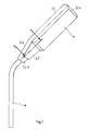
- a mast light 11 is located on a mast 10 at its free end attached.
- the mast light 11 has a light housing 32, which one elongated rectangular cross section; at its in the Fig. 1 left side is a trapezoidal extension 32a formed on the opposite of the bottom 31 (see Fig. 2) lying surface 32b has an opening, not shown, which is closed with a lid 42, the outer contour corresponds to the outer contour of the extension 32a.
- the lamp housing 32 of the mast light 11 is then transparent Cover 32c covered.
- the tubular mast 10 has an interior 12, through which cables (not shown) are threaded.
- the Projection 32a has an entry recess 32d into which the Mast end is plugged in and by means of a radially inward projecting end flange 14 is completed against which strikes the front end of the mast 10 in the assembled state and which encloses or delimits an opening 13, which an oval Cross section, see below.
- In the wall 32b there is the opening 32e which provides access to a connection space 32f releases. This connection space is in the assembled Condition closed by the cover 42.
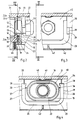
- the opening 13 is, as can be seen from FIGS. 3 and 4, by means of closed a flange plate 15, which is approximately rectangular Has cross section.
- a threaded flange 16 integrally formed, which protrudes perpendicularly to it and so formed is that it fits into opening 13.
- the threaded flange 16 is surrounded by a groove 17 in which a Seal 18 is located against the end face 19 of the end flange 14 is present.
- the groove 17 is from a bar or optionally also surrounded by two strips 20, the height of which Flange plate 15 seen from is lower than that of the threaded flange 16.
- a U-shaped bracket 23 is provided which its inner edges has a retaining groove 24, so that both the Web 25 and the two legs 26 and 27 a U-shaped Have cross-section, the open sides facing each other are.
- the U-shape is chosen so that the narrow side edges the flange plate 15 into the U-shape on the legs 26 and 27 can reach in.
- the bracket 23 has on each of its legs on a broad side, which corresponds to the plane spanned by the bracket 23, one molding 28 each, the outer surface of this plane forms an acute angle, the apex of the angle with the free end of each leg coincides; the cutting line between the broad side of each leg and the outer surface of each
- the molding runs parallel to the longitudinal extension of the web 25 at the end of each leg 26 and 27.
- the molding 28 connects to the outer edges 29 and 30 of the legs 26 and 27 on and covers about half of the legs 26, 27 both in Longitudinal direction of the web as well as in the longitudinal direction of each leg 26, 27 measured.
- the Mast facing side surfaces 35 is chamfered so that the Thickness of each projection 33, 34 on the floor in the longitudinal direction of the Mast or the mast end measured, is thicker than that of the free end of the projection.
- These side surfaces 35 are the Sloping surfaces of the projections 28 adapted so that when the Bracket 23 is mounted together with the flange plate 15, the formations 28 of the legs 26 and 27 touch the inclined surfaces 35 and run onto them and thus a jamming of the flange plate 15 with the bracket 23 on the end face of the end of the end flange 14 effect.
- the flange plate 15 has on the side on which the threaded flange 16 and the outer strips 20 are located, pins 36 and 37, which are at such a distance from one another that the inner edges the legs 26 and 27 to bear against the pins 36, 37 come. So that the bracket 23 with the flange plate 15 a manageable unit is on the side of the plate 15, on which the pins 36 and 37 are located, with lugs 38 and 39, which are at a smaller distance from one another, than the distance of the pins 36, 37 so that the pins are together form a catch with the lugs.
- the flange plate has on the edge facing the bottom 31 15 a recess 40 into which a guide projection 41 engages, thus the flange plate 15 in relation to the bottom 31 Is held in place.
- the cover 42 is located on the projection 32a of the lamp housing 32 attached by means of screws (not shown). In area 23 of the The cover 42 has a bracket running perpendicular to it Support wall 43, which against the outer edge of the web 25 in assembled state and the legs 26 and 27 of the bracket presses against the inclined surface 35 of the projections 32 and 33. Thereby is a bracing of the bracket together with the flange plate 5 ensured.
- the seal 18 serves as one Tolerance compensation.
- a stop seal is also located on the cover 42 44 so that the opening 32e of the connection space 32f seals to the outside is.
- the luminaire housing with the trapezoidal shape Projection 32a inserted over the end of the mast 10 and that Cable passed through the opening 13. Then you thread the cable through the flange plate 15 and then through the cable gland 22 through and the cable gland 22 is in screwed the flange plate so that the cable opposite the Flange plate 15 are sealed. With two cables there are two cable glands can be screwed into the prepared flange plate 15 (not shown). The unit of the flange plate 15 with the bracket 23 and the cable gland 23 is then in front of the End face of the end flange 14 set and the bracket in Pressed towards floor 31.
- connection space 32f There are terminals within the connection space 32f, to which the cables are connected and one of which is electrical Cable routing to the components of the mast light leads.
Landscapes
- Engineering & Computer Science (AREA)
- General Engineering & Computer Science (AREA)
- Arrangement Of Elements, Cooling, Sealing, Or The Like Of Lighting Devices (AREA)
- Fastening Of Light Sources Or Lamp Holders (AREA)
- Lighting Device Outwards From Vehicle And Optical Signal (AREA)
- Forklifts And Lifting Vehicles (AREA)
- Installation Of Indoor Wiring (AREA)
Description
- Fig. 1
- einen Mast mit aufgesetzter Mastleuchte,
- Fig. 2
- eine Schnittansicht gemäß Schnittlinie II-II der Fig. 1,
- Fig. 3
- eine Schnittansicht gemäß Schnittlinie III-III der Fig. 2 und
- Fig. 4
- eine Schnittansicht gemäß Schnittlinie IV-IV der Fig. 2.
Claims (8)
- Vorrichtung zur Halterung und Abdichtung eines Zuführungskabels zu einer am freien Ende eines Mastes aufgebrachten Mastleuchte, mit einer Kabelverschraubung zur Erzielung einer Dichtigkeit vorzugsweise entsprechend IP 54, welche Mastleuchte ein Leuchtengehäuse umfaßt, das an einem Ende einen rohrartigen Fortsatz zum Aufstecken auf das Mastende aufweist, dadurch gekennzeichnet, daß Mittel zur Halterung und Fixierung einer wenigstens einen Durchbruch (21) enthaltenden Flanschplatte (15) am inneren Rohrfortsatzende vorgesehen sind, in welche Durchbrechungen (21) die Kabelverschraubung (22) zur Halterung und Fixierung und Abdichtung des eingeführten, zur Leuchte weiterführenden Kabels einschraubbar ist.
- Vorrichtung nach Anspruch 1, dadurch gekennzeichnet, daß die Mittel einen U-förmigen Haltebügel (23) aufweisen, der an der Innenkante der U-Form wenigstens an den aufeinanderzuweisenden Innenflächen der Schenkel (26, 27) je eine Rille (24) aufweist, in die der Rand der Flanschplatte (15) einfügbar ist, so daß der Haltebügel (23) die Flanschplatte (15) an wenigstens zwei sich gegenüberliegenden Kanten mit seinen Schenkeln (26, 27) umfaßt, und daß der Bügel (23) im Gehäuse festgelegt ist.
- Vorrichtung nach Anspruch 2, mit einem Deckel für einen Anschlußraum für die Leuchte, dadurch gekennzeichnet, daß am Deckel (42) ein Steg (43) angeformt ist, der gegen die Außenkante des Haltebügelsteges (25) drückt.
- Vorrichtung nach Anspruch 3, dadurch gekennzeichnet, daß am Gehäuseboden (31) des Anschlußraumes (32f) zwei seitlich außerhalb der Flanschplatte (15) befindliche Vorsprünge (33, 34) angeordnet sind, gegen deren quer zur Längsrichtung verlaufenden einen Seitenfläche die entsprechenden Seitenflächen der Schenkel (26, 27) des Haltebügels (23) anliegen.
- Vorrichtung nach Anspruch 4, dadurch gekennzeichnet, daß die Seitenflächen der Vorsprünge (33, 34) und des Haltebügels (23) in einem spitzen Winkel zur Senkrechten zur Längserstreckung des Gehäuses bzw. zu dem Gehäuseboden verlaufen, so daß beim Einschieben des Haltebügels (23) und der Flanschplatte (15) eine Verklemmung zwischen den Schenkeln (26, 27) des Haltebügels (23) und den Vorsprüngen (33, 34) erzielt wird.
- Vorrichtung nach einem der vorherigen Ansprüche, dadurch gekennzeichnet, daß die Durchbrüche (22) der Flanschplatte (15) von einer Dichtung (18) umgeben sind, die im montierten Zustand gegen die Stirnkante des Mastendes oder einen als Anschlag für das Mastende vorgesehenen Anschlußflansch (14), der am trapezförmigen Rohrfortsatz (32) nach innen ragend angeformt ist, gedrückt sind.
- Vorrichtung nach einem der vorherigen Ansprüche, dadurch gekennzeichnet, daß am Boden (31) des Gehäuses eine Leiste (41) vorgesehen ist, die in eine daran angepaßte Ausnehmung (42) an der Flanschplatte (15) eingreift.
- Vorrichtung nach einem der vorherigen Ansprüche, dadurch gekennzeichnet, daß an einer Seitenfläche der Flanschplatte (15) Zapfen (36, 37) vorgesehen sind, hinter die Ansätze (38, 39) an den Schenkeln (26, 27) federnd greifen, so daß der Haltebügel (23) und die Flanschplatte (15) miteinander eine vormontierbare Einheit bilden.
Applications Claiming Priority (2)
| Application Number | Priority Date | Filing Date | Title |
|---|---|---|---|
| DE4427711 | 1994-08-05 | ||
| DE4427711A DE4427711C2 (de) | 1994-08-05 | 1994-08-05 | Vorrichtung zur Halterung und Abdichtung eines Zuführungskabels zu einer am freien Ende eines Mastes aufgebrachten Mastleuchte |
Publications (2)
| Publication Number | Publication Date |
|---|---|
| EP0695908A1 EP0695908A1 (de) | 1996-02-07 |
| EP0695908B1 true EP0695908B1 (de) | 2000-03-22 |
Family
ID=6524975
Family Applications (1)
| Application Number | Title | Priority Date | Filing Date |
|---|---|---|---|
| EP95111953A Expired - Lifetime EP0695908B1 (de) | 1994-08-05 | 1995-07-29 | Vorrichtung zur Halterung und Abdichtung eines Zuführungskabels zu einer am freien Ende eines Mastes aufgebrachten Mastleuchte |
Country Status (3)
| Country | Link |
|---|---|
| EP (1) | EP0695908B1 (de) |
| AT (1) | ATE191078T1 (de) |
| DE (2) | DE4427711C2 (de) |
Families Citing this family (1)
| Publication number | Priority date | Publication date | Assignee | Title |
|---|---|---|---|---|
| DE102010000725A1 (de) | 2010-01-07 | 2011-07-14 | ZF Friedrichshafen AG, 88046 | Parksperrenvorrichtung für Kraftfahrzeuggetriebe |
Family Cites Families (13)
| Publication number | Priority date | Publication date | Assignee | Title |
|---|---|---|---|---|
| US2279170A (en) * | 1938-09-14 | 1942-04-07 | Westinghouse Electric & Mfg Co | Insulated support for lighting units |
| US2250855A (en) * | 1939-11-21 | 1941-07-29 | Hubert Scott Paine | Mounting for electric fittings |
| US2337824A (en) * | 1940-06-18 | 1943-12-28 | Westinghouse Electric & Mfg Co | Universal street lighting luminaire |
| DE964521C (de) * | 1954-09-21 | 1957-05-23 | Hoppmann & Mulsow | Dichtungsvorrichtung zum Abdichten von Kabeln in Gewindestutzen elektrischer Geraete |
| DE1825187U (de) * | 1960-07-08 | 1961-01-19 | Deutsche Elektronik Gmbh | Kleines gehaeuse zur aufnahme von elektrischen bauelementen od. dgl. |
| DE1489544A1 (de) * | 1965-08-24 | 1969-03-06 | Schanzenbach & Co Gmbh G | Anschlussvorrichtung,insbesondere fuer Ansatzleuchten |
| DE7909210U1 (de) * | 1979-03-30 | 1979-08-02 | Deutsche Bp Ag, 2000 Hamburg | Abdichtvorrichtung für Kabelkanalrohre |
| US4639843A (en) * | 1985-04-10 | 1987-01-27 | Kidde Consumer Durables, Corporation | Luminaire |
| IT215748Z2 (it) * | 1989-03-07 | 1990-11-05 | Iguzzini Illuminazione | Apparecchiatura di illuminazione con attacco a tenuta per un elemento diffusore. |
| DE4018555A1 (de) * | 1990-06-09 | 1991-12-12 | Willi Flott Fa | Elektrische installationsdose zum einbau in leuchten |
| US5243508A (en) * | 1992-09-30 | 1993-09-07 | Holophane Company, Inc. | Modular luminaire assembly |
| DE9215653U1 (de) * | 1992-11-17 | 1993-02-04 | Briloner Leuchten GmbH, 5790 Brilon | Armatur einer Pfostenleuchte (Pollerleuchte) mit Bewegungsmelder |
| DE4300521A1 (de) * | 1993-01-12 | 1994-07-14 | Weidmueller Interface | Kabelabdichtungs- und Zugentlastungsvorrichtung für Wanddurchbrüche |
-
1994
- 1994-08-05 DE DE4427711A patent/DE4427711C2/de not_active Expired - Lifetime
-
1995
- 1995-07-29 EP EP95111953A patent/EP0695908B1/de not_active Expired - Lifetime
- 1995-07-29 DE DE59508033T patent/DE59508033D1/de not_active Expired - Lifetime
- 1995-07-29 AT AT95111953T patent/ATE191078T1/de not_active IP Right Cessation
Also Published As
| Publication number | Publication date |
|---|---|
| DE59508033D1 (de) | 2000-04-27 |
| DE4427711A1 (de) | 1996-02-15 |
| EP0695908A1 (de) | 1996-02-07 |
| ATE191078T1 (de) | 2000-04-15 |
| DE4427711C2 (de) | 1997-05-28 |
Similar Documents
| Publication | Publication Date | Title |
|---|---|---|
| DE2660162C2 (de) | Gehäuse für leitende Kontaktelemente zum Anschluß an einer elektrischen Leiter | |
| DE3812996A1 (de) | Elektromotor, insbesondere wischermotor zum antrieb einer scheibenwischeranlage in einem kraftfahrzeug | |
| EP0179453A1 (de) | Feuchtraumleuchte | |
| AT505167A4 (de) | Modulares gehäuse, insbesondere für led-signalgeber | |
| EP0695908B1 (de) | Vorrichtung zur Halterung und Abdichtung eines Zuführungskabels zu einer am freien Ende eines Mastes aufgebrachten Mastleuchte | |
| DE3312081A1 (de) | Zenerbarriere | |
| DE19646481C2 (de) | Gehäuse für elektrische Komponenten und Baugruppen | |
| DE19949508A1 (de) | Vorrichtung zur Befestigung von Schirmklemmen | |
| EP0002660B1 (de) | Schaltschrank-Heizgerät | |
| DE8119747U1 (de) | "lichtrohrleuchte" | |
| DE19726748C2 (de) | Kleingehäuse für den Wandanbau | |
| DE4038062C2 (de) | ||
| DE9406388U1 (de) | Mastverbindung für eine Mastleuchte | |
| DE8708237U1 (de) | Steckdosenbox | |
| DE1765056A1 (de) | Anschlussschiene fuer die Versorgung von Verbrauchern mit elektrischem Strom | |
| DE29823871U1 (de) | Schaltschrank mit Kabeleinführung | |
| EP0680123B1 (de) | Schaltschrank für elektrische Anlagen | |
| EP0675583B1 (de) | Aufputzmaterial für ein elektrisches Bauteil, z.B. Schalter, Steckdose und dergleichen | |
| DE29708790U1 (de) | Isolatorsystem für stromführende Leiterdrähte und/oder -bänder für elektrische Weidezäune | |
| DE1464169C (de) | Langfelddeckenleuchte mit einem über die Lange der Entladungslampe erstreckten, hohlpnsmatischen Trag und Anschlußgehause | |
| EP0677702A1 (de) | Leuchte | |
| DE2532550C3 (de) | Gehäuse fUr elektrische oder elektronische Geräte | |
| DE19904949C1 (de) | Abgangsschienenträger zum Einbau in eine elektrische Verteilanlage | |
| DE10131295A1 (de) | Elektrische Installationseinrichtung | |
| DE7424843U (de) | Klemmschellensteg für Verbindungsund Verzweigungsdosen |
Legal Events
| Date | Code | Title | Description |
|---|---|---|---|
| PUAI | Public reference made under article 153(3) epc to a published international application that has entered the european phase |
Free format text: ORIGINAL CODE: 0009012 |
|
| AK | Designated contracting states |
Kind code of ref document: A1 Designated state(s): AT DE FR GB NL |
|
| RAP1 | Party data changed (applicant data changed or rights of an application transferred) |
Owner name: CEAG SICHERHEITSTECHNIK GMBH |
|
| 17P | Request for examination filed |
Effective date: 19960731 |
|
| GRAG | Despatch of communication of intention to grant |
Free format text: ORIGINAL CODE: EPIDOS AGRA |
|
| 17Q | First examination report despatched |
Effective date: 19990601 |
|
| GRAG | Despatch of communication of intention to grant |
Free format text: ORIGINAL CODE: EPIDOS AGRA |
|
| GRAH | Despatch of communication of intention to grant a patent |
Free format text: ORIGINAL CODE: EPIDOS IGRA |
|
| GRAH | Despatch of communication of intention to grant a patent |
Free format text: ORIGINAL CODE: EPIDOS IGRA |
|
| GRAA | (expected) grant |
Free format text: ORIGINAL CODE: 0009210 |
|
| AK | Designated contracting states |
Kind code of ref document: B1 Designated state(s): AT DE FR GB NL |
|
| REF | Corresponds to: |
Ref document number: 191078 Country of ref document: AT Date of ref document: 20000415 Kind code of ref document: T |
|
| GBT | Gb: translation of ep patent filed (gb section 77(6)(a)/1977) |
Effective date: 20000324 |
|
| REF | Corresponds to: |
Ref document number: 59508033 Country of ref document: DE Date of ref document: 20000427 |
|
| ET | Fr: translation filed | ||
| PLBE | No opposition filed within time limit |
Free format text: ORIGINAL CODE: 0009261 |
|
| STAA | Information on the status of an ep patent application or granted ep patent |
Free format text: STATUS: NO OPPOSITION FILED WITHIN TIME LIMIT |
|
| 26N | No opposition filed | ||
| REG | Reference to a national code |
Ref country code: GB Ref legal event code: IF02 |
|
| REG | Reference to a national code |
Ref country code: FR Ref legal event code: CD |
|
| NLT1 | Nl: modifications of names registered in virtue of documents presented to the patent office pursuant to art. 16 a, paragraph 1 |
Owner name: COOPER CROUSE-HINDS GMBH |
|
| PGFP | Annual fee paid to national office [announced via postgrant information from national office to epo] |
Ref country code: AT Payment date: 20070615 Year of fee payment: 13 |
|
| PG25 | Lapsed in a contracting state [announced via postgrant information from national office to epo] |
Ref country code: AT Free format text: LAPSE BECAUSE OF NON-PAYMENT OF DUE FEES Effective date: 20080729 |
|
| PGFP | Annual fee paid to national office [announced via postgrant information from national office to epo] |
Ref country code: GB Payment date: 20140624 Year of fee payment: 20 |
|
| PGFP | Annual fee paid to national office [announced via postgrant information from national office to epo] |
Ref country code: NL Payment date: 20140710 Year of fee payment: 20 Ref country code: DE Payment date: 20140731 Year of fee payment: 20 |
|
| PGFP | Annual fee paid to national office [announced via postgrant information from national office to epo] |
Ref country code: FR Payment date: 20140624 Year of fee payment: 20 |
|
| REG | Reference to a national code |
Ref country code: DE Ref legal event code: R071 Ref document number: 59508033 Country of ref document: DE |
|
| REG | Reference to a national code |
Ref country code: NL Ref legal event code: V4 Effective date: 20150729 |
|
| REG | Reference to a national code |
Ref country code: GB Ref legal event code: PE20 Expiry date: 20150728 |
|
| PG25 | Lapsed in a contracting state [announced via postgrant information from national office to epo] |
Ref country code: GB Free format text: LAPSE BECAUSE OF EXPIRATION OF PROTECTION Effective date: 20150728 |