EP0695914A1 - Elément de cuisson encastrable extra-plat - Google Patents
Elément de cuisson encastrable extra-plat Download PDFInfo
- Publication number
- EP0695914A1 EP0695914A1 EP95401635A EP95401635A EP0695914A1 EP 0695914 A1 EP0695914 A1 EP 0695914A1 EP 95401635 A EP95401635 A EP 95401635A EP 95401635 A EP95401635 A EP 95401635A EP 0695914 A1 EP0695914 A1 EP 0695914A1
- Authority
- EP
- European Patent Office
- Prior art keywords
- built
- cooking element
- element according
- layer
- insulating material
- Prior art date
- Legal status (The legal status is an assumption and is not a legal conclusion. Google has not performed a legal analysis and makes no representation as to the accuracy of the status listed.)
- Granted
Links
- 238000010411 cooking Methods 0.000 title claims abstract description 33
- 238000010438 heat treatment Methods 0.000 claims abstract description 42
- 229910000831 Steel Inorganic materials 0.000 claims abstract description 19
- 239000010959 steel Substances 0.000 claims abstract description 19
- 239000012777 electrically insulating material Substances 0.000 claims abstract description 14
- 239000000919 ceramic Substances 0.000 claims description 10
- 238000001465 metallisation Methods 0.000 claims description 6
- VYZAMTAEIAYCRO-UHFFFAOYSA-N Chromium Chemical compound [Cr] VYZAMTAEIAYCRO-UHFFFAOYSA-N 0.000 claims description 5
- 229910001374 Invar Inorganic materials 0.000 claims description 4
- 229910001030 Iron–nickel alloy Inorganic materials 0.000 claims description 4
- 229910052804 chromium Inorganic materials 0.000 claims description 4
- 239000011651 chromium Substances 0.000 claims description 4
- 210000003298 dental enamel Anatomy 0.000 claims description 4
- 208000001840 Dandruff Diseases 0.000 claims description 2
- 230000005611 electricity Effects 0.000 abstract 1
- 238000007789 sealing Methods 0.000 abstract 1
- 239000011521 glass Substances 0.000 description 5
- 239000002241 glass-ceramic Substances 0.000 description 5
- WGLPBDUCMAPZCE-UHFFFAOYSA-N Trioxochromium Chemical compound O=[Cr](=O)=O WGLPBDUCMAPZCE-UHFFFAOYSA-N 0.000 description 3
- 229910000423 chromium oxide Inorganic materials 0.000 description 3
- 239000007789 gas Substances 0.000 description 3
- 229910052736 halogen Inorganic materials 0.000 description 3
- 150000002367 halogens Chemical class 0.000 description 3
- PXHVJJICTQNCMI-UHFFFAOYSA-N nickel Substances [Ni] PXHVJJICTQNCMI-UHFFFAOYSA-N 0.000 description 3
- QVGXLLKOCUKJST-UHFFFAOYSA-N atomic oxygen Chemical compound [O] QVGXLLKOCUKJST-UHFFFAOYSA-N 0.000 description 2
- 239000004020 conductor Substances 0.000 description 2
- 230000000694 effects Effects 0.000 description 2
- 229910052759 nickel Inorganic materials 0.000 description 2
- 229910052760 oxygen Inorganic materials 0.000 description 2
- 239000001301 oxygen Substances 0.000 description 2
- 208000031968 Cadaver Diseases 0.000 description 1
- 239000000853 adhesive Substances 0.000 description 1
- 230000001070 adhesive effect Effects 0.000 description 1
- 238000009434 installation Methods 0.000 description 1
- 238000009413 insulation Methods 0.000 description 1
- 239000000463 material Substances 0.000 description 1
- 238000000034 method Methods 0.000 description 1
- 238000005476 soldering Methods 0.000 description 1
- 239000002470 thermal conductor Substances 0.000 description 1
Images
Classifications
-
- H—ELECTRICITY
- H05—ELECTRIC TECHNIQUES NOT OTHERWISE PROVIDED FOR
- H05B—ELECTRIC HEATING; ELECTRIC LIGHT SOURCES NOT OTHERWISE PROVIDED FOR; CIRCUIT ARRANGEMENTS FOR ELECTRIC LIGHT SOURCES, IN GENERAL
- H05B3/00—Ohmic-resistance heating
- H05B3/68—Heating arrangements specially adapted for cooking plates or analogous hot-plates
-
- F—MECHANICAL ENGINEERING; LIGHTING; HEATING; WEAPONS; BLASTING
- F24—HEATING; RANGES; VENTILATING
- F24C—DOMESTIC STOVES OR RANGES ; DETAILS OF DOMESTIC STOVES OR RANGES, OF GENERAL APPLICATION
- F24C15/00—Details
- F24C15/10—Tops, e.g. hot plates; Rings
- F24C15/102—Tops, e.g. hot plates; Rings electrically heated
Definitions
- the present invention relates to a built-in cooking element with a heating body, in particular for domestic use.
- Such cooking elements have a thickness of around 25 mm, which allows easy installation in any type of work surface, but does not have a flat work surface due to the presence of gas burners or plates. protruding electrics.
- cooking elements with halogen heaters or radiant heaters. These cooking elements usually consist of a ceramic glass plate stuck in a frame, and one or more heating bodies, in particular halogen heating bodies or radiant heating bodies, placed under the glass ceramic plate at a distance determined from it, of the order of 10 to 20 millimeters.
- the heaters when the heaters are put into service, they emit infrared in the case of halogen heaters and an amount of energy released by the Joule effect in the case of radiant heaters, which lets through the ceramic glass plate and which heat the bottom of the containers.
- vitroceramic type cooking elements are numerous.
- the glass ceramic plate hardly expands with temperature, it lets visible and invisible infrared emitted by the heating bodies placed under it pass, and it is a poor conductor of heat, which makes it possible to isolate the areas located above the heating elements of the rest of the ceramic hob.
- these cooking elements are perfectly flat and very aesthetic.
- vitroceramic type cooking elements nevertheless have a certain number of drawbacks.
- the glass ceramic plate is easily scratched and in addition, it is relatively fragile. Indeed, if a heavy or blunt object falls on this plate, it can split and it is then necessary to replace it.
- the poor heat conduction of the ceramic hobs has the disadvantage of requiring significant energy to heat the area in contact with the bottom of the containers.
- vitroceramic type cooking elements are thicker than the so-called traditional cooking elements, owing to the distance existing between the vitroceramic glass plate and the heating elements, and also due to the very thickness of said element. glass plate.
- vitroceramic cooking elements have a thickness of the order of 45 to 50 mm, which sometimes poses a problem for fitting them flush with the work surfaces.
- the present invention relates to a built-in cooking element having the advantages of glass ceramic cooking elements, but the disadvantages of which are eliminated, and what is more, has a small thickness, of the order of 25 mm.
- the present invention relates more particularly to a built-in cooking element having at least one heating body, characterized in that it comprises a steel support table coated on both sides with a layer of an electrically insulating material, provided with openings in which the heating bodies are embedded, integral with said openings by means of a seal and assembly.
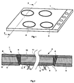
- the built-in cooking element according to the invention consists of a support table 1 and has at least one heating body 2.
- the cooking element has four circular heating bodies 2 and has on its right side a set of control and display keys of known type.
- the heaters are indeed circular, but there are heaters of different shape, for example oblong or ovoid.
- the support table 1 is provided with openings 3 in which the heating bodies 2 are embedded, integral with said openings 3 by means of a seal and assembly 4.
- the openings 3 are preferably frustoconical, the small base of which is situated on the side of the underside of the support table 1 and the periphery of the openings is slightly greater than that of the heating bodies 2.
- this seal is a special adhesive resistant to high temperature and having thermal insulation properties, which makes it possible to avoid the propagation of heat from the heating body 2 to the support table 1.
- This seal is also designed to collect any thermal expansions that the heating body 2 may undergo, and to prevent them from resulting in a deformation of the support table 1.
- the heating bodies 2 are secured to the cooking plate 1 by fixing elements (not shown) of known type, such as by example of the holding tabs integral with the support table 1 and screwed, electrically insulated, to the heating body, or vice versa.
- the support table 1 consists of a steel plate 5 coated on its two faces with a layer 6 of an electrically insulating material.
- the electrically insulating material of each layer 6 is an enamel.
- the support table 1 as shown in the figures is completely planar, but it is conceivable to give it a shape which is not entirely planar, with for example a protruding rim. This operation of conforming the support table 1 is easy due to the drawability of the steel.
- the heating bodies 2 consist of a support layer 7 made of electrically insulating material and an electrically conductive layer 8 comprising electrical supply tracks 9 for its connection to an external energy source.
- the electrically conductive layer 8 is continuous and film-like, that is to say that it covers almost all of the support layer 7 of the heating body 2.
- the electrically conductive layer 8 is located on the side of the underside of the heating body 2, which is not in contact with the containers to be heated.
- the support layer 7 consists of a steel plate 10 coated on both sides with an electrically insulating material 11, preferably an enamel or a ceramic.
- the steel constituting the support layer 7 of the heating bodies 2 is an iron-nickel alloy with a low coefficient of expansion.
- the steel constituting the support layer 7 is a steel known under the brand INVAR, that is to say an iron-nickel alloy with 36% nickel and whose coefficient of expansion is equal to approximately 1.10 ⁇ 6 / ° C.
- the electrically conductive layer 8 is deposited on the support layer 7 of the heating body 2 by vacuum metallization.
- the electrically conductive layer 8 is composed essentially of pure chromium and chromium oxide.
- the proportion of chromium oxide is chosen so as to give said layer 8 the appropriate resistivity to allow its connection to the terminals of an external energy source, generally 220 volts, and dissipate the desired power.
- the quantity of residual oxygen present in the metallization enclosure is controlled during vacuum metallization, and this quantity of oxygen is adjusted. so as to obtain a layer of chromium and chromium oxide having an appropriate resistivity.
- connection to the external energy source can be established by connections 12, 13 made by soldering the ends of appropriate conductors on the rear face of the supply tracks 9.
- This amount of heat will propagate through the support layer 7, electrically insulating but conductive of heat because of its very small thickness, and thus diffuse towards the face of the heating body in contact with the container to be heated.
- the continuous and film-like nature of the conductive layer 8 allows an exemplary heating speed, much faster than with the heating bodies of the prior art.
- the advantage of the heating body according to the invention compared to a heating body of the glass-ceramic type lies in the direct contact between the conductive layer 8 and the support layer 7, which makes it possible to be free from any phenomenon of loss of heat.
- the support layer 7 of the heating body is made of a material which is a good thermal conductor, much better than glass, which allows shorter response times and energy savings.
- the cooking element according to the invention is extra-flat. This is because, on the one hand, of the direct contact between the conductive layer 8 and the support layer 7 of the heating body 2 and, on the other hand, of the small thickness of the support layer 7 of the heating body and of the support table, since these are made from a steel plate, has a maximum total thickness of 25 mm.
- Such a thickness allows embedding in any type of work plan, while keeping the flatness of the assembly.
Landscapes
- Engineering & Computer Science (AREA)
- Chemical & Material Sciences (AREA)
- Combustion & Propulsion (AREA)
- Mechanical Engineering (AREA)
- General Engineering & Computer Science (AREA)
- Resistance Heating (AREA)
- Magnetic Heads (AREA)
- Baking, Grill, Roasting (AREA)
- Electric Stoves And Ranges (AREA)
- Cookers (AREA)
- Glass Compositions (AREA)
Abstract
Description
- La présente invention concerne un élément de cuisson encastrable à corps de chauffe en particulier à usage domestique.
- Il est connu dans le domaine des éléments de cuisson encastrables, des tables de cuisson de type traditionnel à brûleurs à gaz ou à plaques électriques.
- De tels éléments de cuisson ont une épaisseur de l'ordre de 25 mm ce qui permet un encastrement aisé dans tout type de plan de travail, mais ne présentent pas une surface de travail plane du fait de la présence des brûleurs à gaz ou des plaques électriques qui font saillie.
- L'inconvénient de ce type d'élément de cuisson est qu'il n'est pas plan et nécéssite lorsque les corps de chauffe sont des brûleurs à gaz, l'interposition d'une grille support des récipients à chauffer.
- Il est également connu des éléments de cuisson à corps de chauffe halogènes ou à corps de chauffe radiants. Ces éléments de cuisson sont habituellement constitués d'une plaque de verre vitrocéramique collée dans un encadrement, et d'un ou plusieurs corps de chauffe, notamment corps de chauffe halogènes ou corps de chauffe radiants, disposés sous la plaque de verre vitrocéramique à une distance déterminée de celle-ci, de l'ordre de 10 à 20 millimètres.
- Ainsi, lorsque l'on met en service les corps de chauffe, ceux-ci émettent des infrarouges dans le cas des corps de chauffe halogènes et une quantité d'énergie dégagée par effet Joule dans le cas des corps de chauffe radiants, que laisse passer la plaque de verre vitrocéramique et qui permettent de chauffer le fond des récipients.
- Les avantages des éléments de cuisson du type vitrocéramique sont nombreux. En effet, la plaque vitrocéramique ne se dilate quasiment pas avec la température, elle laisse passer les infrarouges visibles et invisibles émis par les corps de chauffe disposés sous elle, et elle est mauvaise conductrice de la chaleur, ce qui permet d'isoler les zones de chauffe situés au dessus des corps de chauffe du reste de la plaque vitrocéramique. De plus ces éléments de cuisson sont parfaitement plans et très esthétiques.
- Ces éléments de cuisson du type vitrocéramique présentent néanmoins un certain nombre d'inconvénients.
- La plaque de verre vitrocéramique est facilement rayable et en plus, elle est relativement fragile. En effet, si un objet lourd ou contondant tombe sur cette plaque, celle-ci peut se fendre et il est alors nécessaire de la remplacer.
- La mauvaise conduction de chaleur des plaques vitrocéramiques présente l'inconvénient de nécessiter une énergie importante pour chauffer la zone en contact avec le fond des récipients.
- De plus, les éléments de cuisson du type vitrocéramique sont plus épais que les éléments de cuisson dits traditionnels, du fait de la distance existante entre la plaque de verre vitrocéramique et les corps de chauffe, et également du fait de l'épaisseur même de ladite plaque de verre.
- De tels éléments de cuisson du type vitrocéramique ont une épaisseur de l'ordre de 45 à 50 mm, ce qui pose parfois problème pour les encastrer en affleurement sur les plans de travail.
- La présente invention a pour objet un élément de cuisson encastrable présentant les avantages des éléments de cuisson vitrocéramique, mais dont les inconvénients sont supprimés, et qui plus est, a une épaisseur faible, de l'ordre de 25 mm.
- La présente invention concerne plus particulièrement un élément de cuisson encastrable présentant au moins un corps de chauffe, caractérisé en ce qu'il comporte une table support en acier revêtu sur ses deux faces d'une couche d'un matériau isolant électriquement, pourvue d'ouvertures dans lesquels sont encastrés les corps de chauffe, solidaires desdites ouvertures au moyen d'une garniture d'étanchéité et d'assemblage.
- Selon d'autres caractéristiques de l'invention :
- les corps de chauffe sont constitués d'une couche support en acier revêtue sur ses deux faces d'un matériau isolant électriquement, et d'une couche conductrice de l'électricité comportant des pistes d'alimentation électrique pour sa connexion à une source d'énergie électrique externe,
- la couche conductrice de l'électricité (8) est continue et pelliculaire.
- la couche conductrice de l'électricité est déposée sur le support en acier revêtu par métallisation sous vide,
- la couche conductrice de l'électricité est du chrome,
- l'acier constitutif de la couche support est un alliage fer-nickel à faible coefficient de dilatation du type INVAR,
- le matériau isolant électriquement est un émail,
- le matériau isolant électriquement est une céramique,
- la céramique est déposée sous vide.
- Les caractéristiques et avantages apparaîtront au cours de la description qui va suivre, donnée uniquement à titre d'exemple, faite en référence aux dessins annexés, dans lesquels:
- la Fig. 1 est une vue en perspective d'un exemple de réalisation d'un élément de cuisson encastrable selon l'invention,
- la Fig. 2 est une vue partielle en coupe selon la ligne 2-2 de la Fig. 1.
- L'élément de cuisson encastrable selon l'invention est constitué d'une table support 1 et présente au moins un corps de chauffe 2.
- Dans l'exemple de réalisation représenté à la Fig. 1, I'élément de cuisson présente quatre corps de chauffe 2, circulaires, et présente sur sa partie droite un jeu de touches de commande et de visualisation de type connu.
- Généralement les corps de chauffe sont en effet circulaires, mais il existe des corps de chauffe de forme différente, par exemple oblongue ou ovoïde.
- La table support 1 est pourvue d'ouvertures 3 dans lesquels sont encastrés les corps de chauffe 2, solidaires desdites ouvertures 3 au moyen d'une garniture d'étanchéité et d'assemblage 4.
- Les ouvertures 3 sont de préférence tronconiques, dont la petite base est située côté de la face inférieure de la table support 1 et le pourtour des ouvertures est légèrement supérieur à celui des corps de chauffe 2.
- Ainsi, lorsque le corps de chauffe 2 est disposé à l'intérieur de l'ouverture 3, il existe un jeu entre ledit corps de chauffe 2 et les bords découpés de la table support 1 pour ménager les ouvertures 3, dans lequel on loge une garniture d'étanchéité et d'assemblage 4.
- Avantageusement, cette garniture d'étanchéité est une colle spéciale résistant à une température élevée et présentant des propriétés d'isolation thermique, ce qui permet d'éviter la propagation de la chaleur du corps de chauffe 2 vers la table support 1.
- Cette garniture d'étanchéité est également conçue pour encaisser les dilatations thermiques éventuelles que peut subir le corps de chauffe 2, et éviter que celles-ci ne se traduisent par une déformation de la table support 1.
- Les corps de chauffe 2 sont solidaires de la plaque de cuisson 1 par des éléments de fixation (non représentés) de type connus, tels que par exemple des pattes de maintien solidaires de la table support 1 et vissés, de manière électriquement isolées, au corps de chauffe, ou inversement.
- La table support 1 selon l'invention est constituée d'une plaque en acier 5 revêtue sur ses deux faces d'une couche 6 d'un matériau isolant électriquement.
- De manière préférentielle, le matériau isolant électriquement de chaque couche 6 est un émail.
- La table support 1 telle que représentée sur les figures est complètement plane, mais on peut envisager de lui conférer une forme non totalement plane, avec par exemple un rebord faisant saillie. Cette opération consistant à conformer la table support 1 est facile du fait du caractère emboutissable de l'acier.
- Les corps de chauffe 2 sont constitués d'une couche support 7 en matériau isolant électriquement et d'une couche conductrice de l'électricité 8 comportant des pistes d'alimentation électrique 9 pour sa connexion à une source d'énergie externe.
- La couche conductrice de l'électricité 8 est continue et pelliculaire, c'est à dire qu'elle recouvre quasiment la totalité de la couche support 7 du corps de chauffe 2.
- La couche conductrice de l'électricité 8 est située du côté de la face inférieure du corps de chauffe 2, qui n'est pas en contact avec les récipients à chauffer.
- La couche support 7 est constituée d'une plaque en acier 10 revêtue sur ses deux faces d'un matériau isolant électriquement 11, de préférence un émail ou une céramique.
- Dans le cas d'une céramique, celle-ci est déposée sous vide sur la plaque en acier 5.
- L'acier constitutif de la couche support 7 des corps de chauffe 2 est un alliage fer-nickel à faible coefficient de dilatation.
- A titre d'exemple, l'acier constitutif de la couche support 7 est un acier connu sous la marque INVAR, c'est à dire un alliage fer-nickel à 36 % de nickel et dont le coefficient de dilatation est égal à environ 1.10⁻⁶/°C.
- Avantageusement, la couche conductrice de l'électricité 8 est déposée sur la couche support 7 du corps de chauffe 2 par métallisation sous vide.
- De manière préferentielle, la couche conductrice de l'électricité 8 est composée essentiellement de chrome pur et d'oxyde de chrome.
- La proportion d'oxyde de chrome est choisie de façon à conférer à ladite couche 8 la résistivité appropriée pour permettre sa connexion aux bornes d'une source d'énergie extérieure , généralement 220 Volts, et dissiper la puissance souhaitée.
- Grâce au procédé de métallisation sous vide d'un support peu ou pas conducteur de l'électricité, on contrôle la quantité d'oxygène résiduelle présente dans l'enceinte de métallisation pendant la métallisation sous vide, et on ajuste cette quantité d'oxygène de façon à obtenir une couche de chrome et d'oxyde de chrome présentant une résistivité appropriée.
- La connexion électrique à la source d'énergie extérieure peut être établie par des connexions 12, 13 réalisés en soudant les extrémités de conducteurs appropriés sur la face arrière des pistes d'alimentation 9.
- Lorsque l'on fait passer le courant électrique aux bornes des connexions 12 et 13 de la couche conductrice 8 du corps de chauffe, celui-ci va circuler à l'intérieur de ladite couche et celle-ci faisant office de résistance va dégager par effet Joule une grande quantité de chaleur.
- Cette quantité de chaleur va se propager à travers la couche support 7, isolante électriquement mais conductrice de la chaleur du fait de sa très faible épaisseur, et ainsi diffuser vers la face du corps de chauffe en contact avec le récipient à chauffer.
- Le caractère continu et pelliculaire de la couche conductrice 8 permet une rapidité de chauffe exemplaire, beaucoup plus rapide qu'avec les corps de chauffe de l'état de la technique.
- L'intérêt du corps de chauffe selon l'invention par rapport à un corps de chauffe du type vitrocéramique réside dans le contact direct entre la couche conductrice 8 et la couche support 7, ce qui permet de s'affranchir de tout phénomène de déperdition de chaleur.
- La couche support 7 du corps de chauffe est réalisée en un matériau bon conducteur thermique, bien meillleur que le verre, ce qui permet des temps de réponse plus courts, et des économies d'énergie.
- L'élément de cuisson selon l'invention est extra-plat. En effet, du fait , d'une part du contact direct entre la couche conductrice 8 et la couche support 7 du corps de chauffe 2 et, d'autre part, de l'épaisseur faible de la couche support 7 du corps de chauffe et de la table support, puisque celles-ci sont réalisées à base d'une plaque en acier, présente une épaisseur totale maximale de 25 mm.
- Une telle épaisseur permet un encastrement dans tout type de plan de travail, tout en gardant la planéité de l'ensemble.
- Enfin un autre intérêt de l'utilisation aussi bien pour la table support 1 que pour les corps de chauffe 2 d'un acier émaillé permet de réaliser des éléments de cuisson de couleur, ce qui confère audit élément de cuisson un nouveau style esthétique.
Claims (9)
Applications Claiming Priority (2)
| Application Number | Priority Date | Filing Date | Title |
|---|---|---|---|
| FR9409700A FR2723430B1 (fr) | 1994-08-04 | 1994-08-04 | Element de cuisson encastrable extra-plat |
| FR9409700 | 1994-08-04 |
Publications (2)
| Publication Number | Publication Date |
|---|---|
| EP0695914A1 true EP0695914A1 (fr) | 1996-02-07 |
| EP0695914B1 EP0695914B1 (fr) | 1998-10-21 |
Family
ID=9466088
Family Applications (1)
| Application Number | Title | Priority Date | Filing Date |
|---|---|---|---|
| EP95401635A Revoked EP0695914B1 (fr) | 1994-08-04 | 1995-07-07 | Elément de cuisson encastrable extra-plat |
Country Status (6)
| Country | Link |
|---|---|
| US (1) | US5679273A (fr) |
| EP (1) | EP0695914B1 (fr) |
| AT (1) | ATE172528T1 (fr) |
| DE (1) | DE69505471T2 (fr) |
| ES (1) | ES2122475T3 (fr) |
| FR (1) | FR2723430B1 (fr) |
Cited By (3)
| Publication number | Priority date | Publication date | Assignee | Title |
|---|---|---|---|---|
| DE19612621A1 (de) * | 1996-03-29 | 1997-10-02 | Schott Glaswerke | Kochfeld mit einer Kochfläche aus Glas-/Glaskeramik |
| EP2192349A3 (fr) * | 2008-12-01 | 2012-05-30 | Wamsler Haus- und Küchentechnik GmbH | Champ de cuisson pour l'agencement sur une source de chaleur |
| EP2615378A1 (fr) * | 2012-01-13 | 2013-07-17 | Electrolux Home Products Corporation N.V. | Plaque de cuisson incluant au moins une plaque de galettière |
Families Citing this family (14)
| Publication number | Priority date | Publication date | Assignee | Title |
|---|---|---|---|---|
| EP0853444B1 (fr) * | 1997-01-10 | 2005-11-23 | E.G.O. ELEKTRO-GERÄTEBAU GmbH | Système à cuire avec une plaque de cuisson électrique, transférant la chaleur par conduction |
| DE29702418U1 (de) * | 1997-02-13 | 1997-03-27 | Schott Glaswerke, 55122 Mainz | Kochgerät mit Glaskeramikkochfläche mit Schnellkochzone |
| US5973298A (en) * | 1998-04-27 | 1999-10-26 | White Consolidated Industries, Inc. | Circular film heater and porcelain enamel cooktop |
| US6297482B1 (en) | 2000-07-26 | 2001-10-02 | Maytag Corporation | Ceramic-based downdraft cooktop having angled front face portion |
| US6501053B2 (en) | 2000-07-26 | 2002-12-31 | Maytag Corporation | Control system for an appliance cooktop |
| USD444024S1 (en) | 2000-07-26 | 2001-06-26 | Maytag Corporation | Ceramic downdraft cooktop having integral, angled front face portion |
| US6410892B1 (en) | 2001-06-19 | 2002-06-25 | Bsh Home Appliances Corporation | Cooktop having a flat glass ceramic cooking surface |
| US7041942B2 (en) * | 2002-11-15 | 2006-05-09 | Engineering Glass Products, Llc | Heating plate assembly for a cooking appliance |
| US20060225627A1 (en) * | 2005-04-08 | 2006-10-12 | Steelcase Development Corporation | Work surface, edge treatment and method for configuring work surface |
| US8814861B2 (en) | 2005-05-12 | 2014-08-26 | Innovatech, Llc | Electrosurgical electrode and method of manufacturing same |
| US7147634B2 (en) | 2005-05-12 | 2006-12-12 | Orion Industries, Ltd. | Electrosurgical electrode and method of manufacturing same |
| NL1036934C2 (nl) * | 2009-05-08 | 2010-11-09 | Abk Innovent B V | Keukeninrichting en werkwijze voor het verschaffen van een werkblad voor een keuken. |
| CN113937606A (zh) * | 2021-10-14 | 2022-01-14 | 浙江水晶光电科技股份有限公司 | 一种电路保护元件及其制备方法 |
| US20250075918A1 (en) * | 2023-09-04 | 2025-03-06 | Chia-Pin Chen | Recessed induction cooker with heat insulation protection pad structure and temperature detection device |
Citations (2)
| Publication number | Priority date | Publication date | Assignee | Title |
|---|---|---|---|---|
| DE2127555A1 (de) * | 1971-06-03 | 1972-12-14 | Siemens-Electrogeräte GmbH, 1000 Berlin u. 8000 München | Kochmulde mit einem Träger aus Glas, Glaskeramik oder Asbestzement |
| EP0229928A2 (fr) * | 1985-12-20 | 1987-07-29 | Bosch-Siemens HausgerÀ¤te GmbH | Elément de chauffage pour appareils de chauffage notamment pour cuisinières |
Family Cites Families (12)
| Publication number | Priority date | Publication date | Assignee | Title |
|---|---|---|---|---|
| US335261A (en) * | 1886-02-02 | weeks | ||
| US3406278A (en) * | 1965-10-12 | 1968-10-15 | Gen Motors Corp | Wattage controller for electrical surface heating unit |
| US3733462A (en) * | 1972-01-11 | 1973-05-15 | Raytheon Co | Heating element for flush top ranges |
| US3805023A (en) * | 1972-03-31 | 1974-04-16 | Horizons Inc | Electrical heating device having metal depositions: in a porous anodized metal layer |
| US3866018A (en) * | 1974-04-01 | 1975-02-11 | Gen Electric | Molded plastic cooktop with heated glass-ceramic plate insert |
| US4009795A (en) * | 1975-12-08 | 1977-03-01 | General Electric Company | Combined reflector pan and trim ring |
| US4237368A (en) * | 1978-06-02 | 1980-12-02 | General Electric Company | Temperature sensor for glass-ceramic cooktop |
| DE3009961C2 (de) * | 1980-03-14 | 1982-10-28 | Schott Glaswerke, 6500 Mainz | Glaskeramik-Kochfeldeinheit zum Einbau in eine Arbeitsplatte |
| CA1241050A (fr) * | 1985-03-22 | 1988-08-23 | W.S. Dominic Ng | Plan de cuisson vitreux encastre dans comptoir |
| DE3728466A1 (de) * | 1987-08-26 | 1989-03-09 | Ego Elektro Blanc & Fischer | Kochgeraet |
| US5185047A (en) * | 1989-12-01 | 1993-02-09 | Whirlpool Corporation | Frameless glass-ceramic cooktop mounting assembly |
| US5221829A (en) * | 1990-10-15 | 1993-06-22 | Shimon Yahav | Domestic cooking apparatus |
-
1994
- 1994-08-04 FR FR9409700A patent/FR2723430B1/fr not_active Expired - Fee Related
-
1995
- 1995-07-07 DE DE69505471T patent/DE69505471T2/de not_active Revoked
- 1995-07-07 AT AT95401635T patent/ATE172528T1/de not_active IP Right Cessation
- 1995-07-07 ES ES95401635T patent/ES2122475T3/es not_active Expired - Lifetime
- 1995-07-07 EP EP95401635A patent/EP0695914B1/fr not_active Revoked
- 1995-08-01 US US08/509,725 patent/US5679273A/en not_active Expired - Fee Related
Patent Citations (2)
| Publication number | Priority date | Publication date | Assignee | Title |
|---|---|---|---|---|
| DE2127555A1 (de) * | 1971-06-03 | 1972-12-14 | Siemens-Electrogeräte GmbH, 1000 Berlin u. 8000 München | Kochmulde mit einem Träger aus Glas, Glaskeramik oder Asbestzement |
| EP0229928A2 (fr) * | 1985-12-20 | 1987-07-29 | Bosch-Siemens HausgerÀ¤te GmbH | Elément de chauffage pour appareils de chauffage notamment pour cuisinières |
Cited By (4)
| Publication number | Priority date | Publication date | Assignee | Title |
|---|---|---|---|---|
| DE19612621A1 (de) * | 1996-03-29 | 1997-10-02 | Schott Glaswerke | Kochfeld mit einer Kochfläche aus Glas-/Glaskeramik |
| DE19612621C2 (de) * | 1996-03-29 | 1999-03-11 | Schott Glas | Kochfeld mit einer Kochfläche aus Glas oder Glaskeramik |
| EP2192349A3 (fr) * | 2008-12-01 | 2012-05-30 | Wamsler Haus- und Küchentechnik GmbH | Champ de cuisson pour l'agencement sur une source de chaleur |
| EP2615378A1 (fr) * | 2012-01-13 | 2013-07-17 | Electrolux Home Products Corporation N.V. | Plaque de cuisson incluant au moins une plaque de galettière |
Also Published As
| Publication number | Publication date |
|---|---|
| ATE172528T1 (de) | 1998-11-15 |
| FR2723430A1 (fr) | 1996-02-09 |
| US5679273A (en) | 1997-10-21 |
| DE69505471T2 (de) | 1999-06-02 |
| ES2122475T3 (es) | 1998-12-16 |
| FR2723430B1 (fr) | 1997-01-03 |
| DE69505471D1 (de) | 1998-11-26 |
| EP0695914B1 (fr) | 1998-10-21 |
Similar Documents
| Publication | Publication Date | Title |
|---|---|---|
| EP0695914B1 (fr) | Elément de cuisson encastrable extra-plat | |
| EP1478291B1 (fr) | Element de panneau avec une couche chauffante | |
| CH640681A5 (fr) | Ensemble electrique chauffant a rayonnement. | |
| EP1627555B1 (fr) | Element feuillete dote d'une couche chauffante | |
| EP0277075A2 (fr) | Plan de cuisson électrique à chauffage à induction | |
| EP0319079A1 (fr) | Elément chauffant en vitrocéramique | |
| FR2494403A1 (fr) | Dispositif electrique chauffant rayonnant pour une table de cuisson en vitroceramique | |
| EP2046571A1 (fr) | Eclairage au moyen de leds | |
| LU87797A1 (fr) | Miroir chauffant | |
| EP0879797A1 (fr) | Plaque vitrocéramique et son procédé de fabrication | |
| FR2948253A1 (fr) | Dispositif de chauffe par induction | |
| EP1629697B1 (fr) | Element en plaque avec un chauffage en couche | |
| CA2451297A1 (fr) | Perfectionnements a la structure d'un four a resistance graphite | |
| FR2502750A3 (fr) | Ensemble comprenant une sonde de temperature pour des elements de chauffage electriques a rayonnement | |
| FR2701545A1 (fr) | Appareil de chauffage électrique d'épaisseur réduite. | |
| WO1999009790A1 (fr) | Panneau chauffant electrique | |
| FR2499808A1 (fr) | Table de cuisson electrique munie d'un dispositif avertisseur de temperature | |
| EP3877700B1 (fr) | Système de chauffe et appareil de cuisson le comportant | |
| FR2908262A1 (fr) | "radiateur seche-serviettes electrique en verre de type echelle" | |
| FR3094171A3 (fr) | Plan de cuisson en ceramique | |
| FR2764050A1 (fr) | Dispositif a fonctions de decoration, notamment de miroir, et d'appareil de chauffage electrique | |
| FR2674318A3 (fr) | Appareil de cuisson portatif. | |
| FR2609160A1 (fr) | Appareil menager de cuisson a plaque support en materiau synthetique ou organique | |
| EP0711098B1 (fr) | Appareil de cuisson à induction | |
| FR3032587A1 (fr) | Panneau de chauffage et d'eclairage |
Legal Events
| Date | Code | Title | Description |
|---|---|---|---|
| PUAI | Public reference made under article 153(3) epc to a published international application that has entered the european phase |
Free format text: ORIGINAL CODE: 0009012 |
|
| AK | Designated contracting states |
Kind code of ref document: A1 Designated state(s): AT BE CH DE DK ES FR GB GR IE IT LI LU NL PT SE |
|
| 17P | Request for examination filed |
Effective date: 19960219 |
|
| 17Q | First examination report despatched |
Effective date: 19970130 |
|
| GRAG | Despatch of communication of intention to grant |
Free format text: ORIGINAL CODE: EPIDOS AGRA |
|
| GRAG | Despatch of communication of intention to grant |
Free format text: ORIGINAL CODE: EPIDOS AGRA |
|
| GRAH | Despatch of communication of intention to grant a patent |
Free format text: ORIGINAL CODE: EPIDOS IGRA |
|
| GRAG | Despatch of communication of intention to grant |
Free format text: ORIGINAL CODE: EPIDOS AGRA |
|
| GRAH | Despatch of communication of intention to grant a patent |
Free format text: ORIGINAL CODE: EPIDOS IGRA |
|
| GRAH | Despatch of communication of intention to grant a patent |
Free format text: ORIGINAL CODE: EPIDOS IGRA |
|
| GRAA | (expected) grant |
Free format text: ORIGINAL CODE: 0009210 |
|
| AK | Designated contracting states |
Kind code of ref document: B1 Designated state(s): AT BE CH DE DK ES FR GB GR IE IT LI LU NL PT SE |
|
| PG25 | Lapsed in a contracting state [announced via postgrant information from national office to epo] |
Ref country code: NL Free format text: LAPSE BECAUSE OF FAILURE TO SUBMIT A TRANSLATION OF THE DESCRIPTION OR TO PAY THE FEE WITHIN THE PRESCRIBED TIME-LIMIT Effective date: 19981021 Ref country code: GR Free format text: LAPSE BECAUSE OF NON-PAYMENT OF DUE FEES Effective date: 19981021 Ref country code: AT Free format text: LAPSE BECAUSE OF FAILURE TO SUBMIT A TRANSLATION OF THE DESCRIPTION OR TO PAY THE FEE WITHIN THE PRESCRIBED TIME-LIMIT Effective date: 19981021 |
|
| REF | Corresponds to: |
Ref document number: 172528 Country of ref document: AT Date of ref document: 19981115 Kind code of ref document: T |
|
| REG | Reference to a national code |
Ref country code: CH Ref legal event code: EP |
|
| REF | Corresponds to: |
Ref document number: 69505471 Country of ref document: DE Date of ref document: 19981126 |
|
| REG | Reference to a national code |
Ref country code: ES Ref legal event code: FG2A Ref document number: 2122475 Country of ref document: ES Kind code of ref document: T3 |
|
| REG | Reference to a national code |
Ref country code: IE Ref legal event code: FG4D Free format text: FRENCH |
|
| GBT | Gb: translation of ep patent filed (gb section 77(6)(a)/1977) |
Effective date: 19981222 |
|
| PG25 | Lapsed in a contracting state [announced via postgrant information from national office to epo] |
Ref country code: PT Free format text: LAPSE BECAUSE OF FAILURE TO SUBMIT A TRANSLATION OF THE DESCRIPTION OR TO PAY THE FEE WITHIN THE PRESCRIBED TIME-LIMIT Effective date: 19990121 Ref country code: DK Free format text: LAPSE BECAUSE OF FAILURE TO SUBMIT A TRANSLATION OF THE DESCRIPTION OR TO PAY THE FEE WITHIN THE PRESCRIBED TIME-LIMIT Effective date: 19990121 |
|
| NLV1 | Nl: lapsed or annulled due to failure to fulfill the requirements of art. 29p and 29m of the patents act | ||
| PLBI | Opposition filed |
Free format text: ORIGINAL CODE: 0009260 |
|
| PG25 | Lapsed in a contracting state [announced via postgrant information from national office to epo] |
Ref country code: LI Free format text: LAPSE BECAUSE OF NON-PAYMENT OF DUE FEES Effective date: 19990731 Ref country code: CH Free format text: LAPSE BECAUSE OF NON-PAYMENT OF DUE FEES Effective date: 19990731 |
|
| PLBF | Reply of patent proprietor to notice(s) of opposition |
Free format text: ORIGINAL CODE: EPIDOS OBSO |
|
| PG25 | Lapsed in a contracting state [announced via postgrant information from national office to epo] |
Ref country code: IE Free format text: LAPSE BECAUSE OF NON-PAYMENT OF DUE FEES Effective date: 19990820 |
|
| 26 | Opposition filed |
Opponent name: BSH BOSCH UND SIEMENS HAUSGERAETE GMBH Effective date: 19990721 |
|
| REG | Reference to a national code |
Ref country code: IE Ref legal event code: FD4D |
|
| REG | Reference to a national code |
Ref country code: CH Ref legal event code: PL |
|
| PGFP | Annual fee paid to national office [announced via postgrant information from national office to epo] |
Ref country code: GB Payment date: 20000614 Year of fee payment: 6 |
|
| PGFP | Annual fee paid to national office [announced via postgrant information from national office to epo] |
Ref country code: SE Payment date: 20000626 Year of fee payment: 6 Ref country code: LU Payment date: 20000626 Year of fee payment: 6 |
|
| PGFP | Annual fee paid to national office [announced via postgrant information from national office to epo] |
Ref country code: FR Payment date: 20000629 Year of fee payment: 6 Ref country code: DE Payment date: 20000629 Year of fee payment: 6 |
|
| PGFP | Annual fee paid to national office [announced via postgrant information from national office to epo] |
Ref country code: BE Payment date: 20000704 Year of fee payment: 6 |
|
| PGFP | Annual fee paid to national office [announced via postgrant information from national office to epo] |
Ref country code: ES Payment date: 20000720 Year of fee payment: 6 |
|
| RDAH | Patent revoked |
Free format text: ORIGINAL CODE: EPIDOS REVO |
|
| RDAG | Patent revoked |
Free format text: ORIGINAL CODE: 0009271 |
|
| STAA | Information on the status of an ep patent application or granted ep patent |
Free format text: STATUS: PATENT REVOKED |
|
| 27W | Patent revoked |
Effective date: 20001113 |
|
| GBPR | Gb: patent revoked under art. 102 of the ep convention designating the uk as contracting state |
Free format text: 20001113 |