EP0696362B1 - Optische vorrichtungen - Google Patents
Optische vorrichtungen Download PDFInfo
- Publication number
- EP0696362B1 EP0696362B1 EP94913745A EP94913745A EP0696362B1 EP 0696362 B1 EP0696362 B1 EP 0696362B1 EP 94913745 A EP94913745 A EP 94913745A EP 94913745 A EP94913745 A EP 94913745A EP 0696362 B1 EP0696362 B1 EP 0696362B1
- Authority
- EP
- European Patent Office
- Prior art keywords
- liquid crystal
- crystal material
- light
- wavelength
- switchable
- Prior art date
- Legal status (The legal status is an assumption and is not a legal conclusion. Google has not performed a legal analysis and makes no representation as to the accuracy of the status listed.)
- Expired - Lifetime
Links
- 230000003287 optical effect Effects 0.000 title description 4
- 239000004973 liquid crystal related substance Substances 0.000 claims abstract description 37
- 239000000463 material Substances 0.000 claims abstract description 24
- 239000000758 substrate Substances 0.000 claims abstract description 9
- 239000005262 ferroelectric liquid crystals (FLCs) Substances 0.000 claims abstract description 5
- 230000005684 electric field Effects 0.000 claims abstract 2
- 239000004990 Smectic liquid crystal Substances 0.000 claims description 3
- 238000002310 reflectometry Methods 0.000 description 6
- 238000001228 spectrum Methods 0.000 description 3
- 238000000411 transmission spectrum Methods 0.000 description 3
- 229910003437 indium oxide Inorganic materials 0.000 description 2
- PJXISJQVUVHSOJ-UHFFFAOYSA-N indium(iii) oxide Chemical compound [O-2].[O-2].[O-2].[In+3].[In+3] PJXISJQVUVHSOJ-UHFFFAOYSA-N 0.000 description 2
- 238000000926 separation method Methods 0.000 description 2
- PFNQVRZLDWYSCW-UHFFFAOYSA-N (fluoren-9-ylideneamino) n-naphthalen-1-ylcarbamate Chemical compound C12=CC=CC=C2C2=CC=CC=C2C1=NOC(=O)NC1=CC=CC2=CC=CC=C12 PFNQVRZLDWYSCW-UHFFFAOYSA-N 0.000 description 1
- 239000004988 Nematic liquid crystal Substances 0.000 description 1
- VYPSYNLAJGMNEJ-UHFFFAOYSA-N Silicium dioxide Chemical compound O=[Si]=O VYPSYNLAJGMNEJ-UHFFFAOYSA-N 0.000 description 1
- 239000000853 adhesive Substances 0.000 description 1
- 230000001070 adhesive effect Effects 0.000 description 1
- 230000005540 biological transmission Effects 0.000 description 1
- 239000000919 ceramic Substances 0.000 description 1
- 239000004020 conductor Substances 0.000 description 1
- 230000007423 decrease Effects 0.000 description 1
- 230000000694 effects Effects 0.000 description 1
- 239000003822 epoxy resin Substances 0.000 description 1
- 229910052732 germanium Inorganic materials 0.000 description 1
- GNPVGFCGXDBREM-UHFFFAOYSA-N germanium atom Chemical compound [Ge] GNPVGFCGXDBREM-UHFFFAOYSA-N 0.000 description 1
- AMGQUBHHOARCQH-UHFFFAOYSA-N indium;oxotin Chemical compound [In].[Sn]=O AMGQUBHHOARCQH-UHFFFAOYSA-N 0.000 description 1
- 230000031700 light absorption Effects 0.000 description 1
- 238000004519 manufacturing process Methods 0.000 description 1
- 239000000203 mixture Substances 0.000 description 1
- 229920000647 polyepoxide Polymers 0.000 description 1
- 229920000642 polymer Polymers 0.000 description 1
- 230000000717 retained effect Effects 0.000 description 1
- 229910052814 silicon oxide Inorganic materials 0.000 description 1
- 125000006850 spacer group Chemical group 0.000 description 1
- 238000001356 surgical procedure Methods 0.000 description 1
- 238000003466 welding Methods 0.000 description 1
Images

Classifications
-
- G—PHYSICS
- G02—OPTICS
- G02F—OPTICAL DEVICES OR ARRANGEMENTS FOR THE CONTROL OF LIGHT BY MODIFICATION OF THE OPTICAL PROPERTIES OF THE MEDIA OF THE ELEMENTS INVOLVED THEREIN; NON-LINEAR OPTICS; FREQUENCY-CHANGING OF LIGHT; OPTICAL LOGIC ELEMENTS; OPTICAL ANALOGUE/DIGITAL CONVERTERS
- G02F1/00—Devices or arrangements for the control of the intensity, colour, phase, polarisation or direction of light arriving from an independent light source, e.g. switching, gating or modulating; Non-linear optics
- G02F1/01—Devices or arrangements for the control of the intensity, colour, phase, polarisation or direction of light arriving from an independent light source, e.g. switching, gating or modulating; Non-linear optics for the control of the intensity, phase, polarisation or colour
- G02F1/21—Devices or arrangements for the control of the intensity, colour, phase, polarisation or direction of light arriving from an independent light source, e.g. switching, gating or modulating; Non-linear optics for the control of the intensity, phase, polarisation or colour by interference
- G02F1/216—Devices or arrangements for the control of the intensity, colour, phase, polarisation or direction of light arriving from an independent light source, e.g. switching, gating or modulating; Non-linear optics for the control of the intensity, phase, polarisation or colour by interference using liquid crystals, e.g. liquid crystal Fabry-Perot filters
-
- G—PHYSICS
- G02—OPTICS
- G02F—OPTICAL DEVICES OR ARRANGEMENTS FOR THE CONTROL OF LIGHT BY MODIFICATION OF THE OPTICAL PROPERTIES OF THE MEDIA OF THE ELEMENTS INVOLVED THEREIN; NON-LINEAR OPTICS; FREQUENCY-CHANGING OF LIGHT; OPTICAL LOGIC ELEMENTS; OPTICAL ANALOGUE/DIGITAL CONVERTERS
- G02F1/00—Devices or arrangements for the control of the intensity, colour, phase, polarisation or direction of light arriving from an independent light source, e.g. switching, gating or modulating; Non-linear optics
- G02F1/01—Devices or arrangements for the control of the intensity, colour, phase, polarisation or direction of light arriving from an independent light source, e.g. switching, gating or modulating; Non-linear optics for the control of the intensity, phase, polarisation or colour
- G02F1/13—Devices or arrangements for the control of the intensity, colour, phase, polarisation or direction of light arriving from an independent light source, e.g. switching, gating or modulating; Non-linear optics for the control of the intensity, phase, polarisation or colour based on liquid crystals, e.g. single liquid crystal display cells
- G02F1/137—Devices or arrangements for the control of the intensity, colour, phase, polarisation or direction of light arriving from an independent light source, e.g. switching, gating or modulating; Non-linear optics for the control of the intensity, phase, polarisation or colour based on liquid crystals, e.g. single liquid crystal display cells characterised by the electro-optical or magneto-optical effect, e.g. field-induced phase transition, orientation effect, guest-host interaction or dynamic scattering
- G02F1/139—Devices or arrangements for the control of the intensity, colour, phase, polarisation or direction of light arriving from an independent light source, e.g. switching, gating or modulating; Non-linear optics for the control of the intensity, phase, polarisation or colour based on liquid crystals, e.g. single liquid crystal display cells characterised by the electro-optical or magneto-optical effect, e.g. field-induced phase transition, orientation effect, guest-host interaction or dynamic scattering based on orientation effects in which the liquid crystal remains transparent
- G02F1/141—Devices or arrangements for the control of the intensity, colour, phase, polarisation or direction of light arriving from an independent light source, e.g. switching, gating or modulating; Non-linear optics for the control of the intensity, phase, polarisation or colour based on liquid crystals, e.g. single liquid crystal display cells characterised by the electro-optical or magneto-optical effect, e.g. field-induced phase transition, orientation effect, guest-host interaction or dynamic scattering based on orientation effects in which the liquid crystal remains transparent using ferroelectric liquid crystals
Definitions
- This invention relates to optical devices and particularly to a liquid crystal shutter for operation in the infrared or other long light wavelength region.
- Liquid crystal (LC) shutters operating in the visible region of the light spectrum are well known, and there are several alternative types, which have different characteristics.
- the simplest is the common twisted nematic shutter which has a switching time of about 30msec.
- Fast response using a nematic liquid crystal material can be obtained from the ⁇ -cell (British Patent Application No. 2184860A) which achieves a switching time of about 1msec.
- the fastest commonly available liquid crystal shutter relies on ferroelectric liquid crystal technology and switches in less than 100 usec.
- a critical parameter of the design of the device is the product of birefringence ( ⁇ n) x thickness (d) and in particular its ratio with the wavelength of operation. All of the above devices ideally require ⁇ nd to equal ⁇ /2 where ⁇ is the light wavelength of interest, normally taken as 550nm for operation in the visible light spectrum.
- Shutters can be classified into two types, namely those which operate over a broad range of wavelengths, and those which are effective over only a restricted range of wavelengths. All of the devices described above are broadband operating; although they are most efficient at the design wavelength, ⁇ 0 , they have useful performance for a range, say, ⁇ 0 ⁇ ⁇ 0 /4. However, in some cases such a broadband capability is not needed, for example when modulating a laser line. Then the shutter needs to be effective only at a single wavelength, or over a very narrow band of wavelengths. Such a device would, for example, be of great value in controlling the output of the CO 2 laser mentioned above, which is used for a variety of marking, cutting and welding operations in fields ranging from surgery to ceramic circuit board manufacture.
- an electrically-controllable liquid crystal filter device as defined in claim 1.
- Figure 1 is a schematic cross-sectional view of a liquid crystal shutter device in accordance with the invention
- Figures 2(a) and 2(b) are schematic pictorial views illustrating the operation of the device.
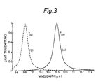
- Figure 3 comprises curves showing the transmission spectra obtained in two operating states of the device.
- a liquid crystal shutter device comprises two flat substrates 1 and 2, which are transparent to light at the required operating wavelength.
- germanium or zinc selenide may be used as the substrate material.
- the substrate 1 has a partially-reflecting mirror 3 on its lower surface (as viewed in Figure 1) and the substrate 2 has such a mirror 4 on its upper surface.
- the mirrors 3 and 4 may be multilayer dielectric stacks, which provide a reflectivity of, say, 95%. The precise value of reflectivity is preferably selected to optimise the performance of the device.
- Each mirror is then coated with an electrode layer 5,6, respectively, of transparent electrically-conductive material, although such layers may be omitted if the substrates and/or the mirrors include conductive layers.
- the layers 5 and 6 are preferably thin (for example less than 30nm thickness) layers of, for example, Indium Oxide (In 2 O 3 ) or Indium Tin Oxide (ITO), the material being selected to have minimum light absorption at the wavelength of interest.
- the electrode layers 5, 6 if provided may be disposed between the substrates 1, 2 and the mirrors 3, 4.
- the mirror surfaces, or the surfaces of the electrode layers 5, 6 if provided, are treated with thin layers 7, 8, respectively, which act to align the moleculus of a liquid crystal layer 10 which is enclosed therebetween.
- the layers 7 and 8 may be, for example, rubbed polymer layers or evaporated silicon oxide layers.
- the two halves of the structure are held apart by spacers (not shown), and the liquid crystal material 10 is retained in the space between the layers 7 and 8 by an adhesive seal 9, which may be an epoxy resin.
- the device of the present invention comprises primarily a Fabry-Perot (FP) filter.
- FP Fabry-Perot
- This comprises two parallel, partially-reflecting mirrors, separated by a small distance, d.
- the transmission spectrum is comb-like, with the peaks separated uniformly in inverse wavelength by 1/2nd, where n is the refractive index of the medium in the cavity between the mirrors. If this is a liquid crystal material, as in the present invention, transmission wavelength can be altered, because the refractive index can be controlled.
- the sharpness of the peaks is determined by the reflectivity of the mirror.
- the device is operated in a low order state, which may be the first order.
- the device of the present invention requires polarised light to operate correctly. However, the majority of lasers generate polarised light, so this is not a disadvantage.
- the material of the layer 10 is a ferroelectric smectic C liquid crystal material, selected such that the smectic C cone angle is 45°.
- An example of such material is a mixture designated CS2004 which is available from Chisso Petrochemical Corporation of Ichihara, Japan.
- the resulting device has two stable states, the optic axes of which are 90° apart. Switching between these two states is controlled by the sign of the voltage applied between the conductive electrode layers; one optic axis orientation is selected by a voltage of one polarity, the other by the opposite polarity.
- n o d When polarised light from a laser impinges on the liquid crystal layer 10, the light experiences, in one operating state of the device, a Fabry-Perot cavity of optical thickness n o d, whereas in the other state the optical thickness is n e d, where n o and n e are the ordinary and extraordinary refractive indices, respectively, of the liquid crystal material, and d is the mirror separation.
- n e and n o may vary for different liquid crystal materials over a range of, say, 0.05 to 0.2, typical values of n e and n o are about 1.6 and about 1.5, respectively, even at a wavelength of 10.6 ⁇ m. Taking the latter values, a device using a liquid crystal layer 3.313 ⁇ m thick will be light transmissive for light of wavelength 10.6 ⁇ m if the light is polarised parallel to the optic axis of the liquid crystal material.
- Figure 2(a) illustrates this situation, wherein an arrow 11 indicates the direction of polarisation of the light and an arrow 12 indicates the optic axis of the liquid crystal material.
- the transmissive peak wavelength moves to about 9.94 ⁇ m and blocks the laser beam, transmitting only a small fraction of the light at 10.6 ⁇ m. For example, if the mirror reflectivity is 95%, only 1.7% of the light is transmitted in this state, leading to a contrast ratio of 58.
- the transmission spectra of the two cases are shown in Figure 3, curves (a) and (b) showing the spectra for the Figure 2(a) and Figure 3(a) situations, respectively.
- the contrast ratio (CR) of this device depends on the mirror reflectivity and the refractive indices of the liquid crystal material, as follows:- where R is the reflectivity of the mirror. This ratio can therefore be altered by selecting the appropriate liquid crystal and mirror combination. Moreover, because the liquid crystal layer is thin, the material operates within the so-called surface-stabilised regime and switching is fast, for example much less than 100 ⁇ sec.
- the embodiment which has been described provides a fast-acting liquid crystal shutter suitable for operating on polarised light at long wavelength.
- This device would be ideally suited for use with a CO 2 laser at a light wavelength of 10.6 ⁇ m. It comprises a liquid crystal Fabry-Perot device designed to operate in low order and to exploit the effects of multiple interference to achieve rapid switching using a thin layer of ferroelectric liquid crystal material.
Landscapes
- Physics & Mathematics (AREA)
- Nonlinear Science (AREA)
- Chemical & Material Sciences (AREA)
- Crystallography & Structural Chemistry (AREA)
- General Physics & Mathematics (AREA)
- Optics & Photonics (AREA)
- Liquid Crystal (AREA)
Claims (4)
- Eine elektrisch steuerbare Flüssigkristallfiltervorrichtung, umfassend zwei teilreflektierende Substrataufbauten, die im wesentlich parallel zueinander und mit einer Entfernung d mit einem Zwischenraum dazwischen zueinander angeordnet sind, um ein Fabry-Perot Filter zu bilden; eine Schicht an ferroelektrischem Flüssigkristallmaterial, das in dem Zwischenraum angeordnet ist, wobei das Flüssigkristallmaterial durch Anwendung eines elekrischen Feldes zwischen verschiedenen Orientierungszuständen darauf schaltbar ist; wobei der gewöhnliche Index n0 und der außergewöhnliche Index ne des Reflexionsvermögens des Flüssigkristallmaterials so ausgewählt werden, daß in einem Orientierungszustand die Vorrichtung durchlässig ist und in dem anderen Orientierungszustand die Vorrichtung für Licht einer besonderen Wellenlänge reflektierend ist,
gekennzeichnet dadurch
daß die besondere Wellenlänge des Lichtes, das zu transmittieren ist, 10.6 µm ist, und die Entfernung d und der Brechungsindex n0 oder ne so ausgewählt werden, daß der Zustand 2nd = m 10.6 µm erfüllt ist, worin m = 1, 2, 3 oder 4 ist, und n entweder n0 oder ne ist. - Vorrichtung nach Anspruch 1,
gekennzeichnet dadurch
daß das Flüssigkristallmaterial ein smektisches C ferroelektrisches Flüssigkristallmaterial ist, das einen Keilwinkel von 45° hat. - Vorrichtung nach Anspruch 2,
gekennzeichnet dadurch
daß die Entfernung d so ist, daß m = 1 ist. - Vorrichtung nach einem der vorangegangenen Ansprüche,
gekennzeichnet dadurch
daß der Flüssigkristallaufbau zwischen den transmittierenden und reflektierenden Zuständen mit einer Geschwindigkeit von weniger als 100 µsec umschaltbar ist.
Applications Claiming Priority (3)
| Application Number | Priority Date | Filing Date | Title |
|---|---|---|---|
| GB9309003 | 1993-04-30 | ||
| GB939309003A GB9309003D0 (en) | 1993-04-30 | 1993-04-30 | Optical devices |
| PCT/GB1994/000931 WO1994025895A1 (en) | 1993-04-30 | 1994-04-29 | Optical devices |
Publications (2)
| Publication Number | Publication Date |
|---|---|
| EP0696362A1 EP0696362A1 (de) | 1996-02-14 |
| EP0696362B1 true EP0696362B1 (de) | 1997-08-27 |
Family
ID=10734775
Family Applications (1)
| Application Number | Title | Priority Date | Filing Date |
|---|---|---|---|
| EP94913745A Expired - Lifetime EP0696362B1 (de) | 1993-04-30 | 1994-04-29 | Optische vorrichtungen |
Country Status (8)
| Country | Link |
|---|---|
| US (1) | US5719654A (de) |
| EP (1) | EP0696362B1 (de) |
| JP (1) | JPH08510334A (de) |
| AU (1) | AU6578194A (de) |
| CA (1) | CA2161633A1 (de) |
| DE (1) | DE69405224T2 (de) |
| GB (2) | GB9309003D0 (de) |
| WO (1) | WO1994025895A1 (de) |
Families Citing this family (11)
| Publication number | Priority date | Publication date | Assignee | Title |
|---|---|---|---|---|
| US5943474A (en) * | 1997-07-09 | 1999-08-24 | Branson Ultrasonics Corporation | Welding method and apparatus |
| US5949959A (en) * | 1997-07-09 | 1999-09-07 | Branson Ultrasonics Corporation | Welding method and apparatus |
| RU2124746C1 (ru) | 1997-08-11 | 1999-01-10 | Закрытое акционерное общество "Кванта Инвест" | Дихроичный поляризатор |
| JP4513258B2 (ja) * | 2002-12-12 | 2010-07-28 | 旭硝子株式会社 | 波長可変フィルタ |
| US6867388B2 (en) * | 2003-04-08 | 2005-03-15 | Branson Ultrasonics Corporation | Electronic masking laser imaging system |
| ITTO20031054A1 (it) * | 2003-12-30 | 2005-06-30 | Ist Trentino Di Cultura | Procedimento per realizzare un dispositivo a microcavita' di fabry-perot integrato in tecnologia al silicio. |
| EP1853947A1 (de) * | 2005-02-15 | 2007-11-14 | Delphi Technologies, Inc. | Filterbaugruppe und verfahren zum filtern elektromagnetischer strahlung |
| CN102331597A (zh) * | 2011-09-22 | 2012-01-25 | 福建福晶科技股份有限公司 | 一种标准具结构 |
| CN102955279A (zh) * | 2012-06-18 | 2013-03-06 | 天津奇谱光电技术有限公司 | 一种可调谐法布里-珀罗滤波器 |
| CN102798998A (zh) * | 2012-07-30 | 2012-11-28 | 天津奇谱光电技术有限公司 | 一种单模连续可调谐光学滤波器 |
| CN115061229B (zh) * | 2022-05-20 | 2023-09-26 | 中国人民解放军火箭军工程大学 | 激光与中远红外兼容隐身膜系结构 |
Family Cites Families (5)
| Publication number | Priority date | Publication date | Assignee | Title |
|---|---|---|---|---|
| US4926177A (en) * | 1987-05-21 | 1990-05-15 | Canon Kabushiki Kaisha | Optical analog-digital converter provided with a nonlinear optical element and an optical feedback system for the output lights of said element |
| US5381253A (en) * | 1991-11-14 | 1995-01-10 | Board Of Regents Of University Of Colorado | Chiral smectic liquid crystal optical modulators having variable retardation |
| US5150236A (en) * | 1990-08-31 | 1992-09-22 | Bell Communications Research, Inc. | Tunable liquid crystal etalon filter |
| WO1992004653A1 (en) * | 1990-08-31 | 1992-03-19 | Bell Communications Research, Inc. | Tunable liquid-crystal etalon filter |
| US5510914A (en) * | 1993-11-15 | 1996-04-23 | The Regents Of The University Of Colorado | Smectic liquid crystal analog phase modulator |
-
1993
- 1993-04-30 GB GB939309003A patent/GB9309003D0/en active Pending
-
1994
- 1994-04-29 CA CA002161633A patent/CA2161633A1/en not_active Abandoned
- 1994-04-29 EP EP94913745A patent/EP0696362B1/de not_active Expired - Lifetime
- 1994-04-29 AU AU65781/94A patent/AU6578194A/en not_active Abandoned
- 1994-04-29 DE DE69405224T patent/DE69405224T2/de not_active Expired - Fee Related
- 1994-04-29 JP JP6524051A patent/JPH08510334A/ja not_active Ceased
- 1994-04-29 GB GB9408575A patent/GB2277808B/en not_active Expired - Fee Related
- 1994-04-29 WO PCT/GB1994/000931 patent/WO1994025895A1/en not_active Ceased
- 1994-04-29 US US08/535,228 patent/US5719654A/en not_active Expired - Fee Related
Also Published As
| Publication number | Publication date |
|---|---|
| JPH08510334A (ja) | 1996-10-29 |
| GB9309003D0 (en) | 1993-06-16 |
| DE69405224D1 (de) | 1997-10-02 |
| US5719654A (en) | 1998-02-17 |
| GB2277808A (en) | 1994-11-09 |
| AU6578194A (en) | 1994-11-21 |
| EP0696362A1 (de) | 1996-02-14 |
| GB2277808B (en) | 1997-01-08 |
| DE69405224T2 (de) | 1998-01-02 |
| WO1994025895A1 (en) | 1994-11-10 |
| CA2161633A1 (en) | 1994-11-10 |
| GB9408575D0 (en) | 1994-06-22 |
Similar Documents
| Publication | Publication Date | Title |
|---|---|---|
| EP1465004B1 (de) | Flüssigkristallfiltereinheit für variable wellenlängen und ansteuerverfahren dafür | |
| US5469279A (en) | Chiral smectic liquid crystal multipass optical filters including a variable retarder (and a variable isotropic spacer) | |
| EP3617793B1 (de) | Abstimmbarer elektro-optischer filter | |
| AU664402B2 (en) | Chiral smectic liquid crystal optical modulators | |
| US5710655A (en) | Cavity thickness compensated etalon filter | |
| US5552912A (en) | Chiral smectic liquid crystal optical modulators | |
| EP0696362B1 (de) | Optische vorrichtungen | |
| EP1659445A1 (de) | Optisches filter mit variabler wellenlänge | |
| EP0348141A1 (de) | Infrarot-Filter mit cholesterischen Flüssigkeiten | |
| EP0895612A1 (de) | Ein abstimmbarer filter | |
| CA2509407A1 (en) | Device and method for an optical tunable polarization interference filter | |
| GB2255193A (en) | Electrically controllable waveplate. | |
| EP1780582A1 (de) | Polarisiertes beugungsfilter und geschichtetes polarisiertes beugungsfilter | |
| US3164665A (en) | Electro-optical light shutter | |
| US7372608B2 (en) | Light control device and light control system using the same | |
| JP4269788B2 (ja) | 反射型光変調素子および可変光減衰器 | |
| Kelly | Application of liquid crystal technology to telecommunication devices | |
| KR20020079821A (ko) | 색 스위치 | |
| JPH05216075A (ja) | 光偏向装置 | |
| JP5150992B2 (ja) | 液晶素子および光減衰器 | |
| CN220381310U (zh) | 一种偏振特性可调的高对比度光栅偏振器 | |
| GB2219099A (en) | Tunable Fabry-Perot filter | |
| JPH05216076A (ja) | 光偏向装置 | |
| EP4478097A1 (de) | Kontraststarker gitterpolarisator mit einstellbarer polarisationscharakteristik | |
| US20040165266A1 (en) | Broadband polarization transformation devices |
Legal Events
| Date | Code | Title | Description |
|---|---|---|---|
| PUAI | Public reference made under article 153(3) epc to a published international application that has entered the european phase |
Free format text: ORIGINAL CODE: 0009012 |
|
| 17P | Request for examination filed |
Effective date: 19951121 |
|
| AK | Designated contracting states |
Kind code of ref document: A1 Designated state(s): BE CH DE DK ES FR GB IE IT LI NL |
|
| GRAG | Despatch of communication of intention to grant |
Free format text: ORIGINAL CODE: EPIDOS AGRA |
|
| 17Q | First examination report despatched |
Effective date: 19961121 |
|
| GRAH | Despatch of communication of intention to grant a patent |
Free format text: ORIGINAL CODE: EPIDOS IGRA |
|
| GRAH | Despatch of communication of intention to grant a patent |
Free format text: ORIGINAL CODE: EPIDOS IGRA |
|
| GRAA | (expected) grant |
Free format text: ORIGINAL CODE: 0009210 |
|
| AK | Designated contracting states |
Kind code of ref document: B1 Designated state(s): BE CH DE DK ES FR IE IT LI NL |
|
| PG25 | Lapsed in a contracting state [announced via postgrant information from national office to epo] |
Ref country code: NL Free format text: LAPSE BECAUSE OF FAILURE TO SUBMIT A TRANSLATION OF THE DESCRIPTION OR TO PAY THE FEE WITHIN THE PRESCRIBED TIME-LIMIT Effective date: 19970827 Ref country code: LI Free format text: LAPSE BECAUSE OF FAILURE TO SUBMIT A TRANSLATION OF THE DESCRIPTION OR TO PAY THE FEE WITHIN THE PRESCRIBED TIME-LIMIT Effective date: 19970827 Ref country code: ES Free format text: THE PATENT HAS BEEN ANNULLED BY A DECISION OF A NATIONAL AUTHORITY Effective date: 19970827 Ref country code: DK Free format text: LAPSE BECAUSE OF NON-PAYMENT OF DUE FEES Effective date: 19970827 Ref country code: CH Free format text: LAPSE BECAUSE OF FAILURE TO SUBMIT A TRANSLATION OF THE DESCRIPTION OR TO PAY THE FEE WITHIN THE PRESCRIBED TIME-LIMIT Effective date: 19970827 Ref country code: BE Effective date: 19970827 |
|
| REG | Reference to a national code |
Ref country code: CH Ref legal event code: EP |
|
| ET | Fr: translation filed | ||
| ITF | It: translation for a ep patent filed | ||
| REF | Corresponds to: |
Ref document number: 69405224 Country of ref document: DE Date of ref document: 19971002 |
|
| NLV1 | Nl: lapsed or annulled due to failure to fulfill the requirements of art. 29p and 29m of the patents act | ||
| REG | Reference to a national code |
Ref country code: CH Ref legal event code: PL |
|
| PG25 | Lapsed in a contracting state [announced via postgrant information from national office to epo] |
Ref country code: IE Free format text: LAPSE BECAUSE OF NON-PAYMENT OF DUE FEES Effective date: 19980429 |
|
| PLBE | No opposition filed within time limit |
Free format text: ORIGINAL CODE: 0009261 |
|
| STAA | Information on the status of an ep patent application or granted ep patent |
Free format text: STATUS: NO OPPOSITION FILED WITHIN TIME LIMIT |
|
| 26N | No opposition filed | ||
| PGFP | Annual fee paid to national office [announced via postgrant information from national office to epo] |
Ref country code: FR Payment date: 20030408 Year of fee payment: 10 |
|
| PGFP | Annual fee paid to national office [announced via postgrant information from national office to epo] |
Ref country code: DE Payment date: 20030508 Year of fee payment: 10 |
|
| PG25 | Lapsed in a contracting state [announced via postgrant information from national office to epo] |
Ref country code: DE Free format text: LAPSE BECAUSE OF NON-PAYMENT OF DUE FEES Effective date: 20041103 |
|
| PG25 | Lapsed in a contracting state [announced via postgrant information from national office to epo] |
Ref country code: FR Free format text: LAPSE BECAUSE OF NON-PAYMENT OF DUE FEES Effective date: 20041231 |
|
| REG | Reference to a national code |
Ref country code: FR Ref legal event code: ST |
|
| PG25 | Lapsed in a contracting state [announced via postgrant information from national office to epo] |
Ref country code: IT Free format text: LAPSE BECAUSE OF NON-PAYMENT OF DUE FEES;WARNING: LAPSES OF ITALIAN PATENTS WITH EFFECTIVE DATE BEFORE 2007 MAY HAVE OCCURRED AT ANY TIME BEFORE 2007. THE CORRECT EFFECTIVE DATE MAY BE DIFFERENT FROM THE ONE RECORDED. Effective date: 20050429 |