EP0696476A2 - Douche - Google Patents
Douche Download PDFInfo
- Publication number
- EP0696476A2 EP0696476A2 EP95111045A EP95111045A EP0696476A2 EP 0696476 A2 EP0696476 A2 EP 0696476A2 EP 95111045 A EP95111045 A EP 95111045A EP 95111045 A EP95111045 A EP 95111045A EP 0696476 A2 EP0696476 A2 EP 0696476A2
- Authority
- EP
- European Patent Office
- Prior art keywords
- pins
- shower
- shower according
- shower head
- jet
- Prior art date
- Legal status (The legal status is an assumption and is not a legal conclusion. Google has not performed a legal analysis and makes no representation as to the accuracy of the status listed.)
- Granted
Links
Images

Classifications
-
- B—PERFORMING OPERATIONS; TRANSPORTING
- B05—SPRAYING OR ATOMISING IN GENERAL; APPLYING FLUENT MATERIALS TO SURFACES, IN GENERAL
- B05B—SPRAYING APPARATUS; ATOMISING APPARATUS; NOZZLES
- B05B1/00—Nozzles, spray heads or other outlets, with or without auxiliary devices such as valves, heating means
- B05B1/02—Nozzles, spray heads or other outlets, with or without auxiliary devices such as valves, heating means designed to produce a jet, spray, or other discharge of particular shape or nature, e.g. in single drops, or having an outlet of particular shape
- B05B1/08—Nozzles, spray heads or other outlets, with or without auxiliary devices such as valves, heating means designed to produce a jet, spray, or other discharge of particular shape or nature, e.g. in single drops, or having an outlet of particular shape of pulsating nature, e.g. delivering liquid in successive separate quantities
- B05B1/083—Nozzles, spray heads or other outlets, with or without auxiliary devices such as valves, heating means designed to produce a jet, spray, or other discharge of particular shape or nature, e.g. in single drops, or having an outlet of particular shape of pulsating nature, e.g. delivering liquid in successive separate quantities the pulsating mechanism comprising movable parts
- B05B1/085—Nozzles, spray heads or other outlets, with or without auxiliary devices such as valves, heating means designed to produce a jet, spray, or other discharge of particular shape or nature, e.g. in single drops, or having an outlet of particular shape of pulsating nature, e.g. delivering liquid in successive separate quantities the pulsating mechanism comprising movable parts rotated by the liquid or other fluent material discharged, e.g. liquid rotated turbines
-
- B—PERFORMING OPERATIONS; TRANSPORTING
- B05—SPRAYING OR ATOMISING IN GENERAL; APPLYING FLUENT MATERIALS TO SURFACES, IN GENERAL
- B05B—SPRAYING APPARATUS; ATOMISING APPARATUS; NOZZLES
- B05B3/00—Spraying or sprinkling apparatus with moving outlet elements or moving deflecting elements
- B05B3/02—Spraying or sprinkling apparatus with moving outlet elements or moving deflecting elements with rotating elements
- B05B3/04—Spraying or sprinkling apparatus with moving outlet elements or moving deflecting elements with rotating elements driven by the liquid or other fluent material discharged, e.g. the liquid actuating a motor before passing to the outlet
-
- B—PERFORMING OPERATIONS; TRANSPORTING
- B05—SPRAYING OR ATOMISING IN GENERAL; APPLYING FLUENT MATERIALS TO SURFACES, IN GENERAL
- B05B—SPRAYING APPARATUS; ATOMISING APPARATUS; NOZZLES
- B05B15/00—Details of spraying plant or spraying apparatus not otherwise provided for; Accessories
- B05B15/50—Arrangements for cleaning; Arrangements for preventing deposits, drying-out or blockage; Arrangements for detecting improper discharge caused by the presence of foreign matter
- B05B15/52—Arrangements for cleaning; Arrangements for preventing deposits, drying-out or blockage; Arrangements for detecting improper discharge caused by the presence of foreign matter for removal of clogging particles
- B05B15/522—Arrangements for cleaning; Arrangements for preventing deposits, drying-out or blockage; Arrangements for detecting improper discharge caused by the presence of foreign matter for removal of clogging particles using cleaning elements penetrating the discharge openings
- B05B15/5223—Arrangements for cleaning; Arrangements for preventing deposits, drying-out or blockage; Arrangements for detecting improper discharge caused by the presence of foreign matter for removal of clogging particles using cleaning elements penetrating the discharge openings the cleaning element, e.g. a needle, and the discharge opening being movable relative to each other in a direction substantially parallel to the flow of liquid or other fluent material through said opening
- B05B15/5225—Arrangements for cleaning; Arrangements for preventing deposits, drying-out or blockage; Arrangements for detecting improper discharge caused by the presence of foreign matter for removal of clogging particles using cleaning elements penetrating the discharge openings the cleaning element, e.g. a needle, and the discharge opening being movable relative to each other in a direction substantially parallel to the flow of liquid or other fluent material through said opening the cleaning element being located upstream of the discharge opening or being actuated upstream therefrom
-
- B—PERFORMING OPERATIONS; TRANSPORTING
- B05—SPRAYING OR ATOMISING IN GENERAL; APPLYING FLUENT MATERIALS TO SURFACES, IN GENERAL
- B05B—SPRAYING APPARATUS; ATOMISING APPARATUS; NOZZLES
- B05B1/00—Nozzles, spray heads or other outlets, with or without auxiliary devices such as valves, heating means
- B05B1/14—Nozzles, spray heads or other outlets, with or without auxiliary devices such as valves, heating means with multiple outlet openings; with strainers in or outside the outlet opening
- B05B1/18—Roses; Shower heads
Definitions
- the invention is based on a shower head with a shower head, a spray disc and a cleaning device.
- a shower is already known (DE-PS 38 04 089), in which a plate is arranged inside the shower head and has a number of pins corresponding to the number of jet outlet openings on its side facing the jet disk. With the help of a slide led through the outer wall of the shower head, the pane can be pushed forward so that the pins get into the jet outlet openings and, if necessary, penetrate existing limescale deposits or other contaminants to the outside. This shower requires a conscious process to perform the cleaning.
- a rotary handle is provided on the side of the shower head for actuating a cleaning device.
- a shower head is known (EP-B-284 801) in which a cleaning device having pins for piercing the jet outlet openings is actuated whenever the shower is switched between two different types of jet. So there is no longer any need to consciously operate the cleaning device.
- the invention has for its object to provide a shower head that has an automatic cleaning of the jet outlet openings and other advantages.
- the invention proposes a shower head with the features listed in claim 1. Developments of the invention are the subject of dependent claims.
- the drive for the cleaning device which is driven by the flowing water, is always actuated as soon as the shower is used. It is possible to ensure that the water pressure is sufficient to operate the cleaning device by means of a corresponding reduction.
- the periodic closing and reopening of the jet outlet openings even if the openings are not completely closed, additionally causes a massage effect and ensures that the water consumption is reduced compared to a shower with the same size jet outlet openings.
- pins are arranged in the same axial position at the same time and are thereby moved simultaneously.
- the pins can be combined into groups, the groups then being able to be driven by the drive.
- the pins of at least two groups have a different position in at least one position of the drive. In this way, a massage effect can be achieved that the user perceives more or better.
- it can be ensured in this way that all jet outlet openings are not closed in any position of the drive.
- the pins are arranged along at least one circle.
- the pins can be fastened within the shower head to a ring element or to partial ring elements, for example injection molded, a circular shape being particularly suitable for a drive.
- the drive has a rotating cam guide for the pins.
- the pins or the elements to which the pins are fastened can engage with a pin in a groove of the rotating cam guide, the rotation of the rotating cam guide then leading to the axial displacement of the pins.
- Various movements can be realized.
- the curve guide has a toothing with which a turbine driven by the water is operatively connected.
- the invention can be provided that of several groups of pins only the pins of one group are arranged in the beam outlet openings. If the shower contains chalky water and if the shower is not used for a long time, it can be ensured that despite a slight sticking of the pins, the force caused by the drive is still sufficient to release the cleaning device.
- the groups each extend over an arc, and neighboring groups assume different axial positions of the pins. In this way, the massage effect can move along the arcs.
- the pins are arranged along at least two concentric circles.
- the pins of two adjacent circles can be positioned differently, so that a massage effect moved from the inside out and back is achieved.
- combinations of these two movements are also advantageously possible.
- the constant cleaning and possibly the massage effect is caused by the drive through the water flow.
- this attachment or the stiffness can be overcome by actuating the manual device. By manual intervention, a greater force is available than would be produced by the water pressure alone. As soon as the cleaning device is loosened again and the stiffness is overcome, the water-operated cleaning device can then be used again.
- the manual actuating device is actuated by attack by the user, for example by turning the jet disc.
- Such a lock can in particular be arranged between a rotating part and a non-rotating part of the shower.
- the lock can have at least one resilient tongue arranged on the one shower head part, in particular molded on, which rests resiliently on the other shower head part, which has at least one contact shoulder extending transversely to the direction of rotation.
- the resilient tongue slides over the other part, and the device is only locked when rotating in the opposite direction of rotation. This means that the manual actuating device is then actuated only by rotating the jet disc in one direction of rotation, for example.
- the contact shoulder is formed by the end of a pocket which is wedge-shaped in the direction of rotation in one of the two shower head parts.
- This pocket can be designed so that when the lock is carried out, the resilient tongue is surrounded on the side with little play, so that it cannot move sideways and also cannot break off.
- the drive can have a rotating cam guide for the pins.
- the barrier between this curve and is preferably provided a shower head part, in particular a distributor disc.
- the shower head of a hand shower shown in FIG. 1 is arranged at the end of a hollow handle 1. Through the hollow handle 1, the water gets into the shower head.
- a jet outlet disk 2 is fastened to the shower head on the lower side in FIG. 1 by means of a central screw 3.
- the screw 3 engages with its thread 4 in a socket 5 provided with an internal thread in the shower head.
- the jet exit disk 2 is sealed along its circumference with respect to the shower head housing by means of a seal 6.
- the jet outlet disk 2 contains three rows of jet outlet openings 7 extending along three concentric circles.
- the spray disc 2 has a cylindrical skirt 8 directed into the interior of the shower head.
- the inside 9 of the apron 8 forms a cylindrical surface.
- a total of eight segments 10 abut this cylindrical surface 9 with their outer surfaces, each of which extends in the circumferential direction over an eighth circle.
- the segments which are identical to one another, are fixed in their circumferential position by inwardly directed, approximately semicircular projections 11 on the inner wall 9 of the apron 8 of the jet disc 2.
- the segments 10 can slide in the direction perpendicular to the jet disk 2, ie in the axial direction along the cylinder surface 9. They contain individual pins 12 on their side facing the jet disk 2.
- the pins 12 are arranged in an axial extension of the jet outlet opening 7.
- a pin 12 on a segment 10 is assigned to each beam outlet opening 7.
- a flat disc 13 On the spray disc 2, on its side directed into the interior of the shower head, a flat disc 13 is fastened, which is perpendicular to the axis of rotation of the screw 3.
- a ring member 14 On the disc 13, a ring member 14 is rotatably supported, which can thus rotate around the screw 3.
- the ring element 14 has a toothing 15 on its inside.
- a gear wheel 18 is rotatably mounted on the inside of the jet disc 2 with the aid of a screw 17 engaging in a bushing 16.
- the gear wheel 18 meshes on the one hand with the toothing 15 of the ring element 14 and on the other hand with another toothed wheel 19.
- the toothed wheel 19 is formed by the external toothing of a bearing bush 20 of a turbine wheel 21.
- the turbine wheel 20 is rotatably supported with its bearing bush 20 on the bush 5 of the shower head. Its axial displaceability is limited by corresponding shoulders on the socket 5 or on the screw 3.
- the turbine wheel 21 has on its side facing away from the jet disk 2 individual inclined turbine blades 22.
- the water reaches the interior of the shower head through an opening 23 from the hollow handle.
- the opening is arranged so that the water hits the blades 22 of the turbine wheel 21. It flows somewhat obliquely into the shower head so that it acts on the wings 22.
- the turbine 21 is rotated by the inflowing water.
- the gear 19 integrally formed on the turbine wheel 21 rotates the gear 18 arranged on the jet disk 2, which in turn rotates the ring element 14.
- each segment 10 has on its inside of a circular arc an approximately centrally arranged pin 26 which engages in this groove 25.
- the pins 26 thus follow the shape of the groove.
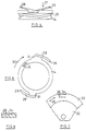
- Fig. 4a shows a possible shape of the groove 25 in the outer cylinder surface 24 of a ring member 14.
- the ring member 14 is shown in the same orientation as in Fig. 1, so that in Fig. 4a below the jet disc is to be thought.
- the groove 25 extends over most of the circumference parallel to the flat end face of the ring element 14 and contains only a section where the groove approaches the lower end face of the ring element 14 in a V-shape or a U-shape.
- the respectively assigned segment 10 is displaced in the direction of the jet disk 2, so that the pins 12 penetrate into the jet outlet openings 7. This is shown on the left in Fig. 1.
- the pins 12 are constantly moved up and down into the beam outlet openings 7 and out of them.
- the pins 12 are combined into groups, each group of pins being formed on a segment 10.
- These segments 10 can be moved individually by the curve guidance. In the embodiment shown, all segments are moved a single groove 25. It is of course also possible to arrange a plurality of grooves on the outer surface 24 of the ring element and to allow the segments to engage with their grooves 26 in different grooves. In this way, a greater degree of freedom in possible movements can be achieved.
- a pawl 27 is formed on the outside of the ring element 14, which is designed to be resilient and rests with its end against a part 21 of the shower head.
- This part 21 of the shower head has, in FIG. 1, invisible contact surfaces running transversely to the circumferential direction, against which the pawl 27 can rest.
- the pawl 27 has the shape of a resilient tongue 28 and is formed on two diametrically offset points of the ring element 14 on the upper side thereof.
- the resilient tongues 28 are located slightly further radially outward than the outer cylinder surface of the ring element. They extend under one Angles of about 15 ° to the plane of the top of the ring element and are relatively thin and narrow. They end in a flat end face 29 which is perpendicular to the plane of the top of the ring element 14 and perpendicular to the circumferential direction shown by the arrow 30.
- FIG. 6 shows the view of the ring element 14 from above, the toothing 15 indicated in FIGS. 2 and 1 being only indicated here.
- the two pawls are formed at the ends of radial projections 31 and run along an arc of a circle.
- the counter element with which the resilient tongues 28 cooperate to form a lock is a distributor disk 32 shown in FIG. 7, which is not present in the embodiment according to FIG. 1. In the embodiment according to FIG. 1, a corresponding design would be provided on the shower part 21.
- the underside of the distributor disk 32 contains a smooth, wide, circular cylindrical ring 33 which has individual pocket-like depressions 34. These pocket-like depressions are arranged at the radial point at which the resilient tongues 28 are also arranged.
- the width of the pocket-like recesses 34 measured in the radial direction, is somewhat larger than the corresponding width of the resilient tongues 28, so that when they lie in the recesses 34, they are guided through the side walls.
- the arrangement is such that the ring element 14 rotates in the opposite direction to the arrow 30 in FIG. 6.
- the resilient tongues thus move in such a way that their end faces 29 are arranged at the rear in the direction of rotation.
- the tongues 28 can thus in the direction of arrow 35 in FIG. 7 Slide over the ring 33, the ends 29 then falling into the recess 34.
Landscapes
- Nozzles (AREA)
- Massaging Devices (AREA)
- Cylinder Crankcases Of Internal Combustion Engines (AREA)
- Sewing Machines And Sewing (AREA)
- Bathtubs, Showers, And Their Attachments (AREA)
Applications Claiming Priority (4)
| Application Number | Priority Date | Filing Date | Title |
|---|---|---|---|
| DE4428788 | 1994-08-13 | ||
| DE4428788A DE4428788A1 (de) | 1994-08-13 | 1994-08-13 | Brausekopf |
| DE19509532 | 1995-03-16 | ||
| DE19509532A DE19509532A1 (de) | 1994-08-13 | 1995-03-16 | Brausekopf |
Publications (3)
| Publication Number | Publication Date |
|---|---|
| EP0696476A2 true EP0696476A2 (fr) | 1996-02-14 |
| EP0696476A3 EP0696476A3 (fr) | 1996-11-20 |
| EP0696476B1 EP0696476B1 (fr) | 1998-12-02 |
Family
ID=25939209
Family Applications (1)
| Application Number | Title | Priority Date | Filing Date |
|---|---|---|---|
| EP95111045A Expired - Lifetime EP0696476B1 (fr) | 1994-08-13 | 1995-07-14 | Douche |
Country Status (7)
| Country | Link |
|---|---|
| US (1) | US5718380A (fr) |
| EP (1) | EP0696476B1 (fr) |
| JP (1) | JPH0866326A (fr) |
| AT (1) | ATE173958T1 (fr) |
| DE (2) | DE19509532A1 (fr) |
| DK (1) | DK0696476T3 (fr) |
| ES (1) | ES2124474T3 (fr) |
Cited By (4)
| Publication number | Priority date | Publication date | Assignee | Title |
|---|---|---|---|---|
| WO1998017401A1 (fr) * | 1996-10-22 | 1998-04-30 | Newteam Limited | Pomme de douche |
| WO2007141551A1 (fr) * | 2006-06-09 | 2007-12-13 | Kohler Mira Limited | Tête de pulvérisation améliorée pour appareils destinés aux ablutions |
| CN108195095A (zh) * | 2018-01-08 | 2018-06-22 | 海宁奇瑞特光电有限公司 | 一种太阳能热水器易清洁喷头 |
| CN108296036A (zh) * | 2016-07-11 | 2018-07-20 | 南安市丽迪家居用品有限公司 | 一种带旋翼的防堵花洒 |
Families Citing this family (87)
| Publication number | Priority date | Publication date | Assignee | Title |
|---|---|---|---|---|
| DE19643199A1 (de) * | 1996-10-19 | 1998-04-23 | Grohe Kg Hans | Brausekopf |
| DE19646655A1 (de) * | 1996-11-12 | 1998-05-14 | Grohe Kg Hans | Brausekopf |
| US6991362B1 (en) | 1998-04-02 | 2006-01-31 | Seaman Anthony E | Agitators for wave-making or mixing as for tanks, and pumps and filters |
| US6488401B1 (en) * | 1998-04-02 | 2002-12-03 | Anthony E. Seaman | Agitators for wave-making or mixing as for tanks, and pumps and filters |
| USD418903S (en) * | 1998-08-26 | 2000-01-11 | Teledyne Industries, Inc. | Wall-mount shower head |
| USD422336S (en) * | 1998-08-26 | 2000-04-04 | Teledyne Industries, Inc. | Hand-held shower head with face plate |
| USD418902S (en) * | 1998-08-26 | 2000-01-11 | Teledyne Industries, Inc. | Hand-held shower head |
| USD415247S (en) * | 1998-08-26 | 1999-10-12 | Teledyne Industries, Inc. | Shower head face plate |
| HK1039083A1 (zh) | 1998-08-26 | 2002-04-12 | Water Pik Inc. | 多功能淋浴喷头 |
| GB2348615B (en) * | 1999-04-08 | 2003-07-16 | Alsons Corp | Showerhead engine assembly |
| US6607148B1 (en) | 2000-01-13 | 2003-08-19 | Kohler Co. | Shower head |
| US6736336B2 (en) | 2000-10-13 | 2004-05-18 | International Concepts, Inc. | Shower head |
| USD457937S1 (en) | 2000-12-12 | 2002-05-28 | Water Pik, Inc. | Classic large handheld shower head |
| USD451980S1 (en) | 2000-12-12 | 2001-12-11 | Water Pik, Inc. | Traditional large handheld shower head |
| USD450807S1 (en) | 2000-12-12 | 2001-11-20 | Water Pik, Inc. | Traditional standard wall-mount shower head |
| USD528631S1 (en) | 2000-12-12 | 2006-09-19 | Water Pik, Inc. | Pan head shower head |
| USD452553S1 (en) | 2000-12-12 | 2001-12-25 | Water Pik, Inc. | Euro large wall-mount shower head |
| USD451583S1 (en) | 2000-12-12 | 2001-12-04 | Water Pik, Inc. | Classic large wall-mount shower head |
| USD451172S1 (en) | 2000-12-12 | 2001-11-27 | Water Pik, Inc. | Euro standard wall-mount shower head |
| USD451169S1 (en) | 2000-12-12 | 2001-11-27 | Water Pik, Inc. | Traditional standard handheld shower head |
| AU2002235211A1 (en) | 2000-12-12 | 2002-06-24 | Water Pik, Inc. | Shower head assembly |
| USD450805S1 (en) | 2000-12-12 | 2001-11-20 | Water Pik, Inc. | Classic standard handheld shower head |
| USD453370S1 (en) | 2000-12-12 | 2002-02-05 | Water Pik, Inc. | Euro large handheld shower head |
| USD450806S1 (en) | 2000-12-12 | 2001-11-20 | Water Pik, Inc. | Modern handheld shower head |
| USD452897S1 (en) | 2000-12-12 | 2002-01-08 | Water Pik, Inc. | Pan head shower head |
| USD453551S1 (en) | 2000-12-12 | 2002-02-12 | Water Pik, Inc. | Modern wall-mount shower head |
| USD452725S1 (en) | 2000-12-12 | 2002-01-01 | Water Pik, Inc. | Euro standard handheld shower head |
| USD451170S1 (en) | 2000-12-12 | 2001-11-27 | Water Pik, Inc. | Classic standard wall-mount shower head |
| USD451171S1 (en) | 2000-12-12 | 2001-11-27 | Water Pik, Inc. | Traditional large wall-mount shower head |
| USD459437S1 (en) | 2001-01-19 | 2002-06-25 | Shower Tek, Inc. | Hand-held shower wand |
| USD450372S1 (en) | 2001-01-19 | 2001-11-13 | Showertek, Inc. | Wall-mount shower head |
| US7114666B2 (en) | 2002-12-10 | 2006-10-03 | Water Pik, Inc. | Dual massage shower head |
| USD485887S1 (en) | 2002-12-10 | 2004-01-27 | Water Pik, Inc. | Pan head style shower head |
| US7533906B2 (en) * | 2003-10-14 | 2009-05-19 | Water Pik, Inc. | Rotatable and pivotable connector |
| USD527440S1 (en) | 2004-09-01 | 2006-08-29 | Water Pik, Inc. | Drenching shower head |
| US7740186B2 (en) | 2004-09-01 | 2010-06-22 | Water Pik, Inc. | Drenching shower head |
| USD533253S1 (en) | 2004-11-03 | 2006-12-05 | Water Pik, Inc. | Elliptical shower head |
| US8733675B2 (en) | 2006-04-20 | 2014-05-27 | Water Pik, Inc. | Converging spray showerhead |
| US8020787B2 (en) | 2006-11-29 | 2011-09-20 | Water Pik, Inc. | Showerhead system |
| US7789326B2 (en) | 2006-12-29 | 2010-09-07 | Water Pik, Inc. | Handheld showerhead with mode control and method of selecting a handheld showerhead mode |
| USD577099S1 (en) | 2006-11-29 | 2008-09-16 | Water Pik, Inc. | Showerhead assembly |
| USD577793S1 (en) | 2006-11-29 | 2008-09-30 | Water Pik, Inc. | Showerhead assembly |
| US8794543B2 (en) | 2006-12-28 | 2014-08-05 | Water Pik, Inc. | Low-speed pulsating showerhead |
| US8366024B2 (en) | 2006-12-28 | 2013-02-05 | Water Pik, Inc. | Low speed pulsating showerhead |
| US7770822B2 (en) | 2006-12-28 | 2010-08-10 | Water Pik, Inc. | Hand shower with an extendable handle |
| US8371618B2 (en) | 2007-05-04 | 2013-02-12 | Water Pik, Inc. | Hidden pivot attachment for showers and method of making same |
| USD581014S1 (en) | 2007-12-20 | 2008-11-18 | Water Pik, Inc. | Hand shower |
| USD590048S1 (en) | 2007-12-20 | 2009-04-07 | Water Pik, Inc. | Hand shower |
| USD580012S1 (en) | 2007-12-20 | 2008-11-04 | Water Pik, Inc. | Showerhead |
| USD603935S1 (en) | 2007-12-20 | 2009-11-10 | Water Pik, Inc. | Hand shower |
| USD592278S1 (en) | 2007-12-20 | 2009-05-12 | Water Pik, Inc. | Showerhead |
| USD580513S1 (en) | 2007-12-20 | 2008-11-11 | Water Pik, Inc. | Hand shower |
| US20090159724A1 (en) * | 2007-12-21 | 2009-06-25 | Kacik Mark S | Turbine valve |
| USD605731S1 (en) | 2007-12-26 | 2009-12-08 | Water Pik, Inc. | Bracket for hand shower |
| USD624156S1 (en) | 2008-04-30 | 2010-09-21 | Water Pik, Inc. | Pivot ball attachment |
| CA2678769C (fr) | 2008-09-15 | 2014-07-29 | Water Pik, Inc. | Ensemble de douche avec changeur de mode radial |
| USD606623S1 (en) | 2008-09-29 | 2009-12-22 | Water Pik, Inc. | Hand shower |
| USD616061S1 (en) | 2008-09-29 | 2010-05-18 | Water Pik, Inc. | Showerhead assembly |
| USD600777S1 (en) | 2008-09-29 | 2009-09-22 | Water Pik, Inc. | Showerhead assembly |
| USD625776S1 (en) | 2009-10-05 | 2010-10-19 | Water Pik, Inc. | Showerhead |
| US8616470B2 (en) | 2010-08-25 | 2013-12-31 | Water Pik, Inc. | Mode control valve in showerhead connector |
| USD678467S1 (en) | 2012-01-27 | 2013-03-19 | Water Pik, Inc. | Ring-shaped handheld showerhead |
| USD678463S1 (en) | 2012-01-27 | 2013-03-19 | Water Pik, Inc. | Ring-shaped wall mount showerhead |
| CA2976867C (fr) | 2012-06-22 | 2021-03-02 | Water Pik, Inc. | Support pour pomme de douche avec regulation de debit integree |
| WO2014019046A1 (fr) * | 2012-08-02 | 2014-02-06 | Fabrimar S/A Indústria E Comércio | Pomme de douche |
| US9404243B2 (en) | 2013-06-13 | 2016-08-02 | Water Pik, Inc. | Showerhead with turbine driven shutter |
| USD744064S1 (en) | 2014-06-13 | 2015-11-24 | Water Pik, Inc. | Handheld showerhead |
| USD744066S1 (en) | 2014-06-13 | 2015-11-24 | Water Pik, Inc. | Wall mount showerhead |
| USD744612S1 (en) | 2014-06-13 | 2015-12-01 | Water Pik, Inc. | Handheld showerhead |
| USD744065S1 (en) | 2014-06-13 | 2015-11-24 | Water Pik, Inc. | Handheld showerhead |
| USD745111S1 (en) | 2014-06-13 | 2015-12-08 | Water Pik, Inc. | Wall mount showerhead |
| USD744614S1 (en) | 2014-06-13 | 2015-12-01 | Water Pik, Inc. | Wall mount showerhead |
| USD744611S1 (en) | 2014-06-13 | 2015-12-01 | Water Pik, Inc. | Handheld showerhead |
| US10413917B2 (en) | 2014-09-03 | 2019-09-17 | Kohler Co. | Shower |
| CN204276183U (zh) * | 2014-11-04 | 2015-04-22 | 东莞市适意洁具有限公司 | 一种自动清洁出水喷口的顶喷 |
| RU2579130C1 (ru) * | 2014-12-15 | 2016-03-27 | Закрытое акционерное общество "БЮРО ТЕХНИКИ" | Душевая насадка |
| CN104923422B (zh) * | 2015-06-29 | 2017-02-01 | 福建欣宇卫浴科技股份有限公司 | 一种圆周回转出水装置 |
| CN108883426B (zh) | 2016-02-01 | 2021-04-27 | 洁碧有限公司 | 手持式宠物用喷射棒 |
| USD803981S1 (en) | 2016-02-01 | 2017-11-28 | Water Pik, Inc. | Handheld spray nozzle |
| USD970684S1 (en) | 2016-04-15 | 2022-11-22 | Water Pik, Inc. | Showerhead |
| US10265710B2 (en) | 2016-04-15 | 2019-04-23 | Water Pik, Inc. | Showerhead with dual oscillating massage |
| CN106076678B (zh) * | 2016-07-22 | 2018-06-12 | 九牧厨卫股份有限公司 | 一种自动除垢花洒及花洒自除垢方法 |
| WO2018049213A1 (fr) | 2016-09-08 | 2018-03-15 | Water Pik, Inc. | Ensemble pause pour pommes de douche |
| USD843549S1 (en) | 2017-07-19 | 2019-03-19 | Water Pik, Inc. | Handheld spray nozzle |
| USD872227S1 (en) | 2018-04-20 | 2020-01-07 | Water Pik, Inc. | Handheld spray device |
| US12071752B2 (en) * | 2018-06-26 | 2024-08-27 | Suresh Kumar Santha | Water shower and a method to save water |
| US11192125B2 (en) | 2018-09-11 | 2021-12-07 | Kohler Co. | Showerhead with pin plate |
Citations (3)
| Publication number | Priority date | Publication date | Assignee | Title |
|---|---|---|---|---|
| US1982538A (en) | 1932-06-04 | 1934-11-27 | Mueller Co | Shower head |
| DE3804089A1 (de) | 1987-02-17 | 1988-08-25 | Armstrong World Ind Inc | Wasserbestaendiges material auf silikat- und polymerbasis und verfahren zu seiner herstellung |
| EP0284801B1 (fr) | 1987-03-12 | 1990-10-24 | Hans Grohe GmbH & Co. KG | Pomme de douche |
Family Cites Families (14)
| Publication number | Priority date | Publication date | Assignee | Title |
|---|---|---|---|---|
| DE377401C (de) * | 1923-06-18 | Carl Rothkegel | Selbsttaetige Reinigungsvorrichtung fuer Brausen | |
| US1236617A (en) * | 1915-09-17 | 1917-08-14 | Speakman Supply & Pipe Company | Self-cleaning shower-head. |
| GB486295A (en) * | 1937-03-20 | 1938-06-01 | Aage Christiansen | Improvements in roses or perforated nozzles |
| DE711583C (de) * | 1937-03-20 | 1941-10-03 | Aage Christiansen | Brause |
| US2251192A (en) * | 1938-09-08 | 1941-07-29 | Mueller Co | Shower head |
| DE804089C (de) * | 1948-12-08 | 1951-04-16 | Emil Schmidtmann | Brause fuer Massen-Badeeinrichtungen |
| DE909919C (de) * | 1951-07-05 | 1954-04-26 | Elektro Stahlbau H J Behncke | Brausekopf, insbesondere fuer sanitaere Zwecke |
| US4018385A (en) * | 1975-11-06 | 1977-04-19 | Leonard Bruno | Oscillating spray head |
| DE2911405C2 (de) * | 1979-03-23 | 1982-12-23 | Hans Grohe Gmbh & Co Kg, 7622 Schiltach | Massagebrause mit einer Einrichtung zur wahlweisen Erzeugung pulsierender und/oder nicht pulsierender Flüssigkeitsstrahlen |
| GB2210566B (en) * | 1987-10-06 | 1991-04-03 | Caradon Mira Ltd | Improved spray head for ablutionary appliances |
| DE4039329C2 (de) * | 1989-12-28 | 2000-02-24 | Grohe Armaturen Friedrich | Brausekopf |
| DE4233694A1 (de) * | 1992-10-07 | 1994-04-14 | Scheffer Ohg Franz | Duscheinrichtung mit selbstreinigendem Brausekopf |
| DE4308988A1 (de) * | 1993-03-20 | 1994-09-22 | Grohe Kg Hans | Brausekopf mit einer Reinigungseinrichtung |
| DE9310730U1 (de) * | 1993-07-17 | 1993-09-02 | Hans Grohe GmbH & Co KG, 77761 Schiltach | Handbrause |
-
1995
- 1995-03-16 DE DE19509532A patent/DE19509532A1/de not_active Withdrawn
- 1995-07-14 AT AT95111045T patent/ATE173958T1/de not_active IP Right Cessation
- 1995-07-14 DE DE59504393T patent/DE59504393D1/de not_active Expired - Fee Related
- 1995-07-14 DK DK95111045T patent/DK0696476T3/da active
- 1995-07-14 EP EP95111045A patent/EP0696476B1/fr not_active Expired - Lifetime
- 1995-07-14 ES ES95111045T patent/ES2124474T3/es not_active Expired - Lifetime
- 1995-07-28 US US08/508,927 patent/US5718380A/en not_active Expired - Fee Related
- 1995-08-09 JP JP7222744A patent/JPH0866326A/ja active Pending
Patent Citations (3)
| Publication number | Priority date | Publication date | Assignee | Title |
|---|---|---|---|---|
| US1982538A (en) | 1932-06-04 | 1934-11-27 | Mueller Co | Shower head |
| DE3804089A1 (de) | 1987-02-17 | 1988-08-25 | Armstrong World Ind Inc | Wasserbestaendiges material auf silikat- und polymerbasis und verfahren zu seiner herstellung |
| EP0284801B1 (fr) | 1987-03-12 | 1990-10-24 | Hans Grohe GmbH & Co. KG | Pomme de douche |
Cited By (6)
| Publication number | Priority date | Publication date | Assignee | Title |
|---|---|---|---|---|
| WO1998017401A1 (fr) * | 1996-10-22 | 1998-04-30 | Newteam Limited | Pomme de douche |
| WO2007141551A1 (fr) * | 2006-06-09 | 2007-12-13 | Kohler Mira Limited | Tête de pulvérisation améliorée pour appareils destinés aux ablutions |
| GB2452222A (en) * | 2006-06-09 | 2009-02-25 | Kohler Mira Ltd | Improved spray head for ablutionary appliances |
| GB2452222B (en) * | 2006-06-09 | 2011-04-27 | Kohler Mira Ltd | Improved spray head for ablutionary appliances |
| CN108296036A (zh) * | 2016-07-11 | 2018-07-20 | 南安市丽迪家居用品有限公司 | 一种带旋翼的防堵花洒 |
| CN108195095A (zh) * | 2018-01-08 | 2018-06-22 | 海宁奇瑞特光电有限公司 | 一种太阳能热水器易清洁喷头 |
Also Published As
| Publication number | Publication date |
|---|---|
| US5718380A (en) | 1998-02-17 |
| DK0696476T3 (da) | 1999-08-16 |
| JPH0866326A (ja) | 1996-03-12 |
| EP0696476B1 (fr) | 1998-12-02 |
| EP0696476A3 (fr) | 1996-11-20 |
| DE19509532A1 (de) | 1996-09-19 |
| DE59504393D1 (de) | 1999-01-14 |
| ATE173958T1 (de) | 1998-12-15 |
| ES2124474T3 (es) | 1999-02-01 |
Similar Documents
| Publication | Publication Date | Title |
|---|---|---|
| EP0696476B1 (fr) | Douche | |
| EP0284801B1 (fr) | Pomme de douche | |
| EP0436496A1 (fr) | Clé pour cylindre de fermeture, notamment pour système de verrouillage | |
| EP0836888A2 (fr) | Pomme de douche | |
| CH636518A5 (de) | Zahnaerztliches handstueck. | |
| DE3329940A1 (de) | Differential | |
| DE3522706C2 (de) | Vorrichtung für Linearantrieb | |
| DE69826809T2 (de) | Federkraftantrieb für ein Schaltgerät, insbesondere für einen Lastschalter | |
| DE7614041U1 (de) | Revolverkopf fuer werkzeugmaschinen | |
| DE1301682B (de) | Schneckengetriebe | |
| DE19928044C2 (de) | Prägestempel | |
| DE3525091A1 (de) | Saevorrichtung | |
| EP0717666B1 (fr) | Porte-brosse reglable en continu | |
| DE2626027A1 (de) | Schwenklager fuer einen kamerastativkopf | |
| EP0875069B1 (fr) | Interrupteur rotatif comportant un dispositif d'arret intermediaire entre les pas de rotation | |
| EP0841096B1 (fr) | Pomme de douche avec dispositif de nettoyage | |
| EP0621081B1 (fr) | Pomme de douche avec dispositif de nettoyage | |
| EP0901837B1 (fr) | Pomme de douche avec aiguilles de nettoyage | |
| DE1016470B (de) | Zaehlwerk | |
| DE4428788A1 (de) | Brausekopf | |
| DE3901322C2 (de) | Brausekopf mit einer Verstelleinrichtung | |
| DE4328296C1 (de) | Sicherheitsschalter | |
| EP0005236B1 (fr) | Dispositif pour le transport de diapositives à travers un projecteur | |
| DE2818479A1 (de) | Sicherheitsschloss | |
| DE1811268C3 (de) | Hydraulische Servolenkeinnchtung |
Legal Events
| Date | Code | Title | Description |
|---|---|---|---|
| PUAI | Public reference made under article 153(3) epc to a published international application that has entered the european phase |
Free format text: ORIGINAL CODE: 0009012 |
|
| AK | Designated contracting states |
Kind code of ref document: A2 Designated state(s): AT BE CH DE DK ES FR GB LI NL |
|
| PUAL | Search report despatched |
Free format text: ORIGINAL CODE: 0009013 |
|
| AK | Designated contracting states |
Kind code of ref document: A3 Designated state(s): AT BE CH DE DK ES FR GB LI NL |
|
| 17P | Request for examination filed |
Effective date: 19961116 |
|
| 17Q | First examination report despatched |
Effective date: 19970325 |
|
| GRAG | Despatch of communication of intention to grant |
Free format text: ORIGINAL CODE: EPIDOS AGRA |
|
| GRAG | Despatch of communication of intention to grant |
Free format text: ORIGINAL CODE: EPIDOS AGRA |
|
| GRAG | Despatch of communication of intention to grant |
Free format text: ORIGINAL CODE: EPIDOS AGRA |
|
| GRAH | Despatch of communication of intention to grant a patent |
Free format text: ORIGINAL CODE: EPIDOS IGRA |
|
| GRAH | Despatch of communication of intention to grant a patent |
Free format text: ORIGINAL CODE: EPIDOS IGRA |
|
| GRAA | (expected) grant |
Free format text: ORIGINAL CODE: 0009210 |
|
| AK | Designated contracting states |
Kind code of ref document: B1 Designated state(s): AT BE CH DE DK ES FR GB LI NL |
|
| PG25 | Lapsed in a contracting state [announced via postgrant information from national office to epo] |
Ref country code: NL Free format text: LAPSE BECAUSE OF FAILURE TO SUBMIT A TRANSLATION OF THE DESCRIPTION OR TO PAY THE FEE WITHIN THE PRESCRIBED TIME-LIMIT Effective date: 19981202 |
|
| REF | Corresponds to: |
Ref document number: 173958 Country of ref document: AT Date of ref document: 19981215 Kind code of ref document: T |
|
| REG | Reference to a national code |
Ref country code: CH Ref legal event code: NV Representative=s name: TROESCH SCHEIDEGGER WERNER AG Ref country code: CH Ref legal event code: EP |
|
| REF | Corresponds to: |
Ref document number: 59504393 Country of ref document: DE Date of ref document: 19990114 |
|
| REG | Reference to a national code |
Ref country code: ES Ref legal event code: FG2A Ref document number: 2124474 Country of ref document: ES Kind code of ref document: T3 |
|
| GBT | Gb: translation of ep patent filed (gb section 77(6)(a)/1977) |
Effective date: 19990125 |
|
| ET | Fr: translation filed | ||
| NLV1 | Nl: lapsed or annulled due to failure to fulfill the requirements of art. 29p and 29m of the patents act | ||
| PG25 | Lapsed in a contracting state [announced via postgrant information from national office to epo] |
Ref country code: AT Free format text: LAPSE BECAUSE OF NON-PAYMENT OF DUE FEES Effective date: 19990714 |
|
| PG25 | Lapsed in a contracting state [announced via postgrant information from national office to epo] |
Ref country code: BE Free format text: LAPSE BECAUSE OF NON-PAYMENT OF DUE FEES Effective date: 19990731 |
|
| REG | Reference to a national code |
Ref country code: DK Ref legal event code: T3 |
|
| PLBE | No opposition filed within time limit |
Free format text: ORIGINAL CODE: 0009261 |
|
| STAA | Information on the status of an ep patent application or granted ep patent |
Free format text: STATUS: NO OPPOSITION FILED WITHIN TIME LIMIT |
|
| 26N | No opposition filed | ||
| BERE | Be: lapsed |
Owner name: HANS GROHE G.M.B.H. & CO. K.G. Effective date: 19990731 |
|
| REG | Reference to a national code |
Ref country code: GB Ref legal event code: IF02 |
|
| PGFP | Annual fee paid to national office [announced via postgrant information from national office to epo] |
Ref country code: DK Payment date: 20070725 Year of fee payment: 13 |
|
| PGFP | Annual fee paid to national office [announced via postgrant information from national office to epo] |
Ref country code: CH Payment date: 20070724 Year of fee payment: 13 |
|
| PGFP | Annual fee paid to national office [announced via postgrant information from national office to epo] |
Ref country code: GB Payment date: 20070730 Year of fee payment: 13 |
|
| PGFP | Annual fee paid to national office [announced via postgrant information from national office to epo] |
Ref country code: ES Payment date: 20080723 Year of fee payment: 14 Ref country code: DE Payment date: 20080814 Year of fee payment: 14 |
|
| PGFP | Annual fee paid to national office [announced via postgrant information from national office to epo] |
Ref country code: FR Payment date: 20080718 Year of fee payment: 14 |
|
| REG | Reference to a national code |
Ref country code: CH Ref legal event code: PL |
|
| REG | Reference to a national code |
Ref country code: DK Ref legal event code: EBP |
|
| GBPC | Gb: european patent ceased through non-payment of renewal fee |
Effective date: 20080714 |
|
| PG25 | Lapsed in a contracting state [announced via postgrant information from national office to epo] |
Ref country code: LI Free format text: LAPSE BECAUSE OF NON-PAYMENT OF DUE FEES Effective date: 20080731 Ref country code: GB Free format text: LAPSE BECAUSE OF NON-PAYMENT OF DUE FEES Effective date: 20080714 Ref country code: CH Free format text: LAPSE BECAUSE OF NON-PAYMENT OF DUE FEES Effective date: 20080731 |
|
| PG25 | Lapsed in a contracting state [announced via postgrant information from national office to epo] |
Ref country code: DK Free format text: LAPSE BECAUSE OF NON-PAYMENT OF DUE FEES Effective date: 20080731 |
|
| REG | Reference to a national code |
Ref country code: FR Ref legal event code: ST Effective date: 20100331 |
|
| PG25 | Lapsed in a contracting state [announced via postgrant information from national office to epo] |
Ref country code: FR Free format text: LAPSE BECAUSE OF NON-PAYMENT OF DUE FEES Effective date: 20090731 |
|
| PG25 | Lapsed in a contracting state [announced via postgrant information from national office to epo] |
Ref country code: DE Free format text: LAPSE BECAUSE OF NON-PAYMENT OF DUE FEES Effective date: 20100202 |
|
| REG | Reference to a national code |
Ref country code: ES Ref legal event code: FD2A Effective date: 20090715 |
|
| PG25 | Lapsed in a contracting state [announced via postgrant information from national office to epo] |
Ref country code: ES Free format text: LAPSE BECAUSE OF NON-PAYMENT OF DUE FEES Effective date: 20090715 |