EP0696477A2 - Protection par flux laminaire d'un jet fluide - Google Patents
Protection par flux laminaire d'un jet fluide Download PDFInfo
- Publication number
- EP0696477A2 EP0696477A2 EP95112403A EP95112403A EP0696477A2 EP 0696477 A2 EP0696477 A2 EP 0696477A2 EP 95112403 A EP95112403 A EP 95112403A EP 95112403 A EP95112403 A EP 95112403A EP 0696477 A2 EP0696477 A2 EP 0696477A2
- Authority
- EP
- European Patent Office
- Prior art keywords
- fluid
- shielding
- stream
- turbulent flow
- passageway
- Prior art date
- Legal status (The legal status is an assumption and is not a legal conclusion. Google has not performed a legal analysis and makes no representation as to the accuracy of the status listed.)
- Ceased
Links
Images

Classifications
-
- B—PERFORMING OPERATIONS; TRANSPORTING
- B05—SPRAYING OR ATOMISING IN GENERAL; APPLYING FLUENT MATERIALS TO SURFACES, IN GENERAL
- B05B—SPRAYING APPARATUS; ATOMISING APPARATUS; NOZZLES
- B05B1/00—Nozzles, spray heads or other outlets, with or without auxiliary devices such as valves, heating means
- B05B1/28—Nozzles, spray heads or other outlets, with or without auxiliary devices such as valves, heating means with integral means for shielding the discharged liquid or other fluent material, e.g. to limit area of spray; with integral means for catching drips or collecting surplus liquid or other fluent material
-
- C—CHEMISTRY; METALLURGY
- C23—COATING METALLIC MATERIAL; COATING MATERIAL WITH METALLIC MATERIAL; CHEMICAL SURFACE TREATMENT; DIFFUSION TREATMENT OF METALLIC MATERIAL; COATING BY VACUUM EVAPORATION, BY SPUTTERING, BY ION IMPLANTATION OR BY CHEMICAL VAPOUR DEPOSITION, IN GENERAL; INHIBITING CORROSION OF METALLIC MATERIAL OR INCRUSTATION IN GENERAL
- C23C—COATING METALLIC MATERIAL; COATING MATERIAL WITH METALLIC MATERIAL; SURFACE TREATMENT OF METALLIC MATERIAL BY DIFFUSION INTO THE SURFACE, BY CHEMICAL CONVERSION OR SUBSTITUTION; COATING BY VACUUM EVAPORATION, BY SPUTTERING, BY ION IMPLANTATION OR BY CHEMICAL VAPOUR DEPOSITION, IN GENERAL
- C23C4/00—Coating by spraying the coating material in the molten state, e.g. by flame, plasma or electric discharge
- C23C4/12—Coating by spraying the coating material in the molten state, e.g. by flame, plasma or electric discharge characterised by the method of spraying
-
- B—PERFORMING OPERATIONS; TRANSPORTING
- B05—SPRAYING OR ATOMISING IN GENERAL; APPLYING FLUENT MATERIALS TO SURFACES, IN GENERAL
- B05B—SPRAYING APPARATUS; ATOMISING APPARATUS; NOZZLES
- B05B7/00—Spraying apparatus for discharge of liquids or other fluent materials from two or more sources, e.g. of liquid and air, of powder and gas
- B05B7/02—Spray pistols; Apparatus for discharge
- B05B7/08—Spray pistols; Apparatus for discharge with separate outlet orifices, e.g. to form parallel jets, i.e. the axis of the jets being parallel, to form intersecting jets, i.e. the axis of the jets converging but not necessarily intersecting at a point
- B05B7/0807—Spray pistols; Apparatus for discharge with separate outlet orifices, e.g. to form parallel jets, i.e. the axis of the jets being parallel, to form intersecting jets, i.e. the axis of the jets converging but not necessarily intersecting at a point to form intersecting jets
- B05B7/0861—Spray pistols; Apparatus for discharge with separate outlet orifices, e.g. to form parallel jets, i.e. the axis of the jets being parallel, to form intersecting jets, i.e. the axis of the jets converging but not necessarily intersecting at a point to form intersecting jets with one single jet constituted by a liquid or a mixture containing a liquid and several gas jets
Definitions
- the invention relates to fluid shielding methods and apparatuses which are useful for various industrial applications, such as plasma spray deposition.
- Fluid streams are often shielded from their surrounding environments to prevent contamination in many industrial processes.
- the shielding is normally carried out by surrounding the fluid streams with a shielding fluid, such as an inert gas.
- the shielding fluid prevents reactive gases, such as oxygen, in the fluid streams' surrounding environments from infiltrating into the fluid streams.
- U.S. Patent No. 3,470,347 discloses a method for producing a substantially oxygen-free coating on a substrate by the use of a plasma arc coating torch.
- the torch produces an arc plasma through a constricting nozzle orifice so as to provide a high velocity, high energy arc effluent which carries coating materials to be deposited onto the substrate.
- the effluent is protected from its surrounding environment by surrounding it with a uniform turbulent flow of a coaxial annular shielding gas stream having a certain width and a certain forward momentum.
- the coaxial annular shielding gas stream can only protect the effluent containing coating materials for a short distance.
- a low temperature melting material such as plastic powder
- This material needs to be blown into the effluent of the torch through a tube as the effluent emerges from the nozzle in order to prevent overheating of the material.
- blowing the material, as well as the tube disrupts and/or blocks the flow of the coaxial annular shielding gas and causes the effluent to be unprotected.
- U.S. Patent No. 4,869,936 discloses a method for shielding a particle-carrying high velocity oxyfuel flame stream.
- the shielding method involves ejecting the particle-carrying high velocity oxyfuel flame stream into a shielding cylinder and using a plurality of nozzles to produce a high velocity tangential flow around the particle-carrying high velocity oxyfuel flame stream within the shielding cylinder.
- the shielding cylinder may fail after a short period of operation due to the combination of high temperature and high gas velocity. This may necessitate frequent shut downs to replace the shielding cylinder.
- U.S. Patent No. 4,992,337 discloses an electric arc spray process for the deposition of reactive metals.
- the reactive metals are sprayed from the electric arc with compressed inert atomizing gases.
- the sprayed reactive metals would be rapidly mixed with air and would experience some oxidation before being deposited on a substrate. This process is not effective for shielding, among other things, plasma arc sprays, gas atomization of molten metals or high velocity oxyfuel flame streams.
- a process for shielding a fluid containing stream from its surrounding environment comprising:
- a fluid shielding system comprising:
- laminar flow means root means square of velocity fluctuations that are less than 0.1 times average velocity.
- turbulent flow means root means square of velocity fluctuations that are greater than 0.1 times average velocity.
- plenum means an enclosed chamber for distributing gases.
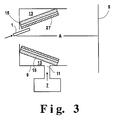
- Figures 1, 2 and 3 show cross-sectional views of preferred embodiments of the invention, which are useful for shielding a turbulent fluid with inert gas.
- a turbulent flow of a fluid containing stream is ejected from at least on nozzle having at least one opening.
- the turbulent stream (1a) may be formed from any liquid or gaseous stream including an inert gas.
- the turbulent stream may be heated, e.g., heated to about 1000 °C to about 10,000 °C as in the case of plasma spray deposition.
- the heated turbulent stream may be obtained from known thermal spray processes that use chemical combustion or electric arc heating to generate heat.
- Some chemical combustion thermal spraying techniques include powder flame spraying, wire/rod flame spraying and detonation/explosive spraying.
- Some electric heating thermal spraying techniques include wire arc spraying and plasma arc spraying.
- an inert gas such as argon
- an electric arc is subject to an electric arc and then is ejected from at least one nozzle (1) to produce a high temperature turbulent stream, e.g., a turbulent stream at a temperature of about 10,000 °C.
- the turbulent stream can be, among other things, electric arc streams, plasma arc streams, flame streams (oxy-fuel or air-fuel flame), effluent from flames, molten droplets streams (liquid spray streams produced by pressure or gas atomization) and other streams containing particles or droplets.
- Coating materials may be introduced into a hot turbulent stream after or before the hot turbulent stream is ejected from the nozzle (1).
- the coating materials may be in the form of powder, wire, or rod depending on the particular process.
- the coating materials are in powder form and are introduced into the hot turbulent stream through a conveying means (3), such as at least one tube, with a powder conveying gas.
- a conveying means (3) such as at least one tube, with a powder conveying gas.
- the coating materials are introduced into the hot turbulent stream, they are entrained in the turbulent stream and are heated to a softened or molten state.
- the coating materials are introduced in the form of wire or rod, the coating materials are atomized.
- the molten or softened coating material confined or entrained within the turbulent stream is then directed at a substrate (5) to deposit the coating, materials.
- the coating material may be selected from, among other things, plastics, metals, alloys, oxides, ceramics, hard intermetallic and metallic compounds and certain glasses.
- Shielding fluid is delivered from a source (7) to an elongated hollow body (9).
- the elongated hollow body has at least one inlet (11) for receiving the shielding fluid, at least one plenum (13) for distributing the shielding fluid and at least one porous diffusing wall (15) for emitting the shielding fluid.
- the delivered shielding fluid enters the plenum (13) through the inlet (11) and leaves the plenum (13) through at least one porous wall (15) to produce an effective laminar flow.
- the formation of the laminar flow is promoted by using the plenum (13) having the desired depth (25), e.g., 1/8 inch, or more and the porous wall (15) having a well distributed plurality of pores having a diameter in the range of about 0.2 to about 1000 micron, preferably about 2 to about 20 micron.
- the plenum (13) is deep enough to attain a fairly uniform distribution of gas through the porous internal wall (15) which in turn allows it to emit an effective laminar flow from the well or uniformly distributed plurality of pores.
- Other gas distributing means such as a screen, may also be used to produce a laminar flow even though they may be less effective.
- the laminar flow of the shielding fluid is directed transversely to the flowing direction of the turbulent stream.
- the shielding fluid By providing the laminar flow of the shielding fluid transversely, the shielding fluid is effectively entrained and distributed along the length of the turbulent stream as the turbulent stream flows toward a desired point, e.g., a substrate to be coated (5).
- the effective entrainment and distribution of the shielding fluid along the length of the turbulent stream minimizes the oxidation or contamination or degradation of materials, such as powder, droplets and/or particles, within the turbulent stream since, reactive gases, such as oxygen, in the turbulent stream's surrounding environment is prevented or substantially prevented from being entrained in the turbulent gas.
- the amount of the shielding fluid used is such that the oxygen level or other reactive gas levels at the point of the impact, e.g., the surface of a substrate to be coated (5), is less than 1%, preferably less than 0.01%.
- the laminar flow of the shielding fluid is provided at a point near where the turbulent stream is ejected, e.g., within 2 inches from a point where the turbulent stream is ejected, so that the shielding fluid is well distributed along the length of the turbulent stream.
- the shielding fluid is an inert fluid, such as nitrogen, argon, hydrogen or mixtures thereof.
- the inert fluid, such as nitrogen may contain up to 5% by volume oxygen.
- Such inert fluid can be obtained from a pressure or temperature swing adsorption system or a membrane gas separation system.
- the porous diffusing wall (15) may be made with any solid material.
- Some of the materials useful for making the porous diffusing surface include sintered alloy, ceramic particles, ceramic cloth, metal particles, plastic particles, stainless steel particles.
- the type of materials used to construct the porous diffusing wall (15) normally varies depending on the particular process involved, i.e., the end usage. However, an oxidation resisting material, e.g., stainless steel, is generally preferred as a constructing material for the porous diffusing surface especially if it is to be used in high temperature coating, e.g., plasma coating.
- the porous diffusing surface has both porosity and thickness sufficient to provide a pressure drop of about 1 to 10 psig with the shielding gas flowing in order to ensure uniform distribution of shielding gas.
- This pressure drop is also found to allow the shielding gas to cool the porous diffusing surface, e.g., reduce overheating caused by a hot plasma stream, and minimize the deposition of stray particles, or metal or chemical vapor from the turbulent stream on the porous diffusing surface. Deposition of the straying particles or vapors can be further minimized if a screen means, e.g., stainless steel screens having openings having a cross-sectional area of about 1 mm to about 10 mm, is used to cover and protect the porous diffusing surface.
- a screen means e.g., stainless steel screens having openings having a cross-sectional area of about 1 mm to about 10 mm
- the shape of the outer surface (17) of the porous diffusing wall (15) may be such that the shielding fluid is emitted transversely to the turbulent stream.
- the outer porous diffusing surface (17) may define a passageway (19) having various shapes and sizes to allow the shielding fluid to flow transversely or perpendicularly to the axis (A) of the passageway (19).
- the length (22) of the passageway (19) may vary from one particular process to another, i.e., depending on the desired objective.
- the preferred length is normally equal to or greater than 1/4 of the radius of the passageway (19) in the case of the cylindrical passageway.
- the most preferred length is equal to or greater than the radius of the passageway (19).
- the passageway formed by at least in part by the porous outer surface (17) of the diffusing wall (15) does not materially affect the ejection angle of the turbulent stream.
- the turbulent stream can be ejected at an angle in the range of about 0° to about ⁇ 70°, measured from the axis (A) of the passageway.
- the porous diffusing surface in the form of a passageway is, not only proven to be useful for providing the desired shielding fluid flow in a desired direction, but also proven to be useful for blocking a large fraction of the ultra violet lights given off by certain turbulent streams, e.g. plasma arc streams.
- the outer surface of the porous diffusing wall need not form a passageway or need not be part of a passageway to surround the turbulent stream with the shielding fluid. As long as the laminar flow of the shielding fluid can be emitted transversely from an appropriate location to the flowing direction of the turbulent stream, the turbulent stream can be reasonably effectively shielded.
- the system illustrated in Figure 1 was used to carry out a shielding process.
- a gas stream having 90% argon and 10% hydrogen flowing at about 100 normal cubic feet per hour was subjected to a 30 kilowatt electric arc to form a turbulent plasma stream.
- the turbulent plasma stream was ejected from a nozzle (1).
- the nozzle (1) has an opening or orifice which diameter is about 0.25 inch.
- the cylindrical passageway (19) defined by the outer surface (17) of the porous diffusing wall (15) has a diameter (21) of about 5 inches.
- the diameter (21) be larger than or equal to 1/4 of a plenum standoff distance (23), i.e., a distance between the outlet end of the passageway and a target or a substrate (5), to ensure that the turbulent plasma stream will remain inert until it strikes the target or substrate (5).
- the diameter (21) is normally not critical. It can be as large as convenient.
- the depth (25) of the plenum (13) was 2 inches. This depth (25), however, can be reduced to as small as 1/8 inch and still can obtain good performance. A small depth can be important in reducing the size and weight associated with the plenum (13).
- the plenum (13) need only be deep enough to attain a fairly uniform distribution of gas through the porous wall (15).
- the length (22) of the plenum was about 3 inches. It is preferably at least as long as 1/8 of the diameter (21) of the passageway (19). For smaller lengths, air is entrained into in the shielding gas flow prior the shielding gas flow being entrained into the turbulent jet. There is no upper limit on the length (22) of the plenum (13).
- the porous wall (15) had a thickness of about 0.062 inch and a porosity (a pore diameter) of about 2 microns. A thicker porous wall will have greater mechanical strength but a higher pressure drop. A larger porosity wall has a lower pressure drop, but might have a less uniform distribution of gas flow through it.
- a wire mesh screen (27) is suitable if the shielding gas is distributed uniformly within the plenum (13) by gas distributing means such as a porous tube (14).
- a removable wire mesh screen (21) can be placed on the outer surface (17) of the porous wall (15) to help prevent metal splatter from adhering to the porous wall (15). If the wire mesh (27) becomes plugged, it is easily removed and replaced.
- the porous wall was made of stainless steel, such as those sold under the tradename "316 stainless steel". It is, however, understood that other materials, such as metal alloys, ceramics, ceramic cloths and even plastics, can be used, depending upon the specific application.
- the nozzle (1) was sealed to the plenum (13) with a metal cover (29).
- This cover improves performance by helping to prevent air entrainment in the initial portion of the turbulent jet. It, however, is not required.
- the distance (31) from the opening of the nozzle (1) to the closest end of the plenum (13) was about 1.5 inches. This distance (31) is preferably less than 4 times the diameter (21) of the passageway (19) to prevent recirculation of the turbulent stream heating of the metal cover (29).
- the distance (31) is most preferably between 0.5 times the porous wall diameter and -0.5 times the length (22) of the porous wall (15) to prevent heating of the metal cover (29) by radiation from the plasma.
- the distance (31) is preferably less than 4 times the passageway diameter (21) to prevent air entrainment into the turbulent stream. It is most preferably between 0 and -0.5 times the length (22) of the porous wall (15).
- a negative distance (31) is a distance the nozzle entered into the passageway, measured from the entrance end of the passageway to the nozzle opening.
- the shield gas flow rate was about 3,000 ncfh of nitrogen. This gave an oxygen level measured at the substrate (15) of less than about 0.01%. This flow rate gives a low oxygen level at the target and gives suitable low oxide levels in the deposit.
- the flow rate of the shielding gas is normally proportional to the nozzle stand off distance (33) or to the turbulent stream flow.
- a surprising feature of this invention is that reduced oxide deposits can be obtained even when the shield gas flow rate is lower than what is required to get low oxygen levels at the substrate.
- the oxygen level at the substrate was about 10%.
- a nickel deposit had reduced oxide levels as evidenced by easy machining.
- the shielding gas was turned off, the nickel deposit had high oxide levels as evidenced by difficult to machining. It appears that the shield gas is preferentially entrained into the turbulent stream near the orifice where the temperature is highest and oxidation most rapid. If the flow rate is less than that required to get a low oxygen level in the gas at the substrate, then the metal cover (29) is preferentially employed to insure that the shield gas is entrained in the initial portion of the turbulent stream.
- High purity nitrogen (less than 10 ppm impurities) was used for the shield gas.
- Any shield gas suitable to the process can be used.
- a preferred shield gas is a flammable mixture with a flame ignited at the interface between the shield gas and the ambient air. This flame stabilizes the flow and allows for plenum standoff distances (23) to be greater than 4 times the passageway diameter (21).
- a preferred gas composition for high vapor pressure metals is a mixture containing controlled levels of oxidizing gases such as O2, CO2 and H2O. The total oxidizing potential of the mixture is less than that of air. The controlled oxidation level reduces the vapor pressure of the metals without forming excessive oxides. Zinc, magnesium and iron are three metals that have significant vapor pressures near their melting points.
- a shielding process was carried out using the shielding system illustrated in Figure 1.
- the conditions were the same as example 1 except for the following conditions: A nitrogen jet flow rate from a nozzle having an orifice diameter of about 0.25 inch is about 200 ncfh at room temperature; a nitrogen shielding gas flow rate is about 250 ncfh; the passageway formed by a porous surface has a diameter of about 1 7/8 inches and a length of about 2 inches; and the distance between a metal cover or other sealing means (29) and the closest end of the plenum (13) is about 0 inch.
- the experiment was repeated using the same conditions except that the nitrogen shielding gas was heated to about 540 °F before it was introduced into the plenum (13).
- Heating the shielding gas to 540 °F increased the 1% O2 standoff distance from 2.94 inches to 3.88 inches. This is an increase of about 32%.
- additional shielding fluid or gas is provided coaxially with respect to the turbulent stream.
- the additional shielding fluid flow is preferably laminar.
Landscapes
- Chemical & Material Sciences (AREA)
- Engineering & Computer Science (AREA)
- Mechanical Engineering (AREA)
- Plasma & Fusion (AREA)
- Chemical Kinetics & Catalysis (AREA)
- Materials Engineering (AREA)
- Physics & Mathematics (AREA)
- Metallurgy (AREA)
- Organic Chemistry (AREA)
- Nozzles (AREA)
- Application Of Or Painting With Fluid Materials (AREA)
- Arc Welding In General (AREA)
- Details Or Accessories Of Spraying Plant Or Apparatus (AREA)
Applications Claiming Priority (2)
| Application Number | Priority Date | Filing Date | Title |
|---|---|---|---|
| US286200 | 1988-12-19 | ||
| US08/286,200 US5486383A (en) | 1994-08-08 | 1994-08-08 | Laminar flow shielding of fluid jet |
Publications (2)
| Publication Number | Publication Date |
|---|---|
| EP0696477A2 true EP0696477A2 (fr) | 1996-02-14 |
| EP0696477A3 EP0696477A3 (fr) | 1996-07-17 |
Family
ID=23097532
Family Applications (1)
| Application Number | Title | Priority Date | Filing Date |
|---|---|---|---|
| EP95112403A Ceased EP0696477A3 (fr) | 1994-08-08 | 1995-08-07 | Protection par flux laminaire d'un jet fluide |
Country Status (7)
| Country | Link |
|---|---|
| US (1) | US5486383A (fr) |
| EP (1) | EP0696477A3 (fr) |
| JP (1) | JPH0857358A (fr) |
| KR (1) | KR100234574B1 (fr) |
| CN (1) | CN1142829C (fr) |
| BR (1) | BR9503570A (fr) |
| CA (1) | CA2155596C (fr) |
Cited By (1)
| Publication number | Priority date | Publication date | Assignee | Title |
|---|---|---|---|---|
| US6589263B1 (en) | 1999-07-30 | 2003-07-08 | Incept Llc | Vascular device having one or more articulation regions and methods of use |
Families Citing this family (21)
| Publication number | Priority date | Publication date | Assignee | Title |
|---|---|---|---|---|
| US5662266A (en) * | 1995-01-04 | 1997-09-02 | Zurecki; Zbigniew | Process and apparatus for shrouding a turbulent gas jet |
| US5911249A (en) | 1997-03-13 | 1999-06-15 | Jescorp, Inc. | Gassing rail apparatus and method |
| US6202388B1 (en) | 1998-11-06 | 2001-03-20 | Jescorp, Inc. | Controlled environment sealing apparatus and method |
| US6525288B2 (en) * | 2001-03-20 | 2003-02-25 | Richard B. Rehrig | Gas lens assembly for a gas shielded arc welding torch |
| KR100436540B1 (ko) * | 2001-11-23 | 2004-06-19 | 한국수력원자력 주식회사 | Co₂ 분사제염 발생 오염입자 포집방법 및 장치 |
| US20050026001A1 (en) * | 2003-07-31 | 2005-02-03 | Taylor Thomas A. | Shielded ceramic thermal spray coating |
| US7045172B2 (en) * | 2003-07-31 | 2006-05-16 | Praxair S.T. Technology, Inc. | Method of shielding effluents in spray devices |
| US11267003B2 (en) | 2005-05-13 | 2022-03-08 | Delta Faucet Company | Power sprayer |
| WO2006124721A2 (fr) * | 2005-05-13 | 2006-11-23 | Masco Corporation Of Indiana | Pulverisateur puissant |
| US8424781B2 (en) * | 2006-02-06 | 2013-04-23 | Masco Corporation Of Indiana | Power sprayer |
| GB0621388D0 (en) * | 2006-10-27 | 2006-12-06 | Rolls Royce Plc | A support matrix arrangement |
| CN101842629A (zh) * | 2007-08-28 | 2010-09-22 | 气体产品与化学公司 | 用于在低温构件上提供无冷凝液和无霜表面的设备和方法 |
| DE202007019184U1 (de) * | 2007-09-11 | 2010-12-30 | Maschinenfabrik Reinhausen Gmbh | Vorrichtung zur Behandlung oder Beschichtung von Oberflächen |
| DE102011002069A1 (de) * | 2011-04-14 | 2012-10-18 | Nordenia Deutschland Gronau Gmbh | Klebstoffdüse zum Aufbringen von Klebstoff auf eine bewegte Materialbahn |
| US20130157040A1 (en) * | 2011-12-14 | 2013-06-20 | Christopher A. Petorak | System and method for utilization of shrouded plasma spray or shrouded liquid suspension injection in suspension plasma spray processes |
| SG11201403108RA (en) * | 2011-12-14 | 2014-09-26 | Praxair Technology Inc | Reactive gas shroud or flame sheath for suspension plasma spray processes |
| KR101996433B1 (ko) * | 2012-11-13 | 2019-07-05 | 삼성디스플레이 주식회사 | 박막 형성 장치 및 그것을 이용한 박막 형성 방법 |
| CN104941844A (zh) * | 2015-07-08 | 2015-09-30 | 福建省雾精灵环境科技有限公司 | 一种风送喷雾机 |
| CN105289913B (zh) * | 2015-11-09 | 2018-01-05 | 郑州立佳热喷涂机械有限公司 | 液体燃料轴心送粉环缝塞式超音速喷枪 |
| CN105855078B (zh) * | 2016-06-15 | 2017-05-03 | 北京航空航天大学 | 一种具有多孔旋流壁的离心喷嘴和喷雾方法 |
| JP7090467B2 (ja) * | 2018-05-15 | 2022-06-24 | 東京エレクトロン株式会社 | 溶射装置 |
Citations (4)
| Publication number | Priority date | Publication date | Assignee | Title |
|---|---|---|---|---|
| US3470347A (en) | 1968-01-16 | 1969-09-30 | Union Carbide Corp | Method for shielding a gas effluent |
| US4869936A (en) | 1987-12-28 | 1989-09-26 | Amoco Corporation | Apparatus and process for producing high density thermal spray coatings |
| US4992337A (en) | 1990-01-30 | 1991-02-12 | Air Products And Chemicals, Inc. | Electric arc spraying of reactive metals |
| US5154354A (en) | 1988-02-01 | 1992-10-13 | Nova-Werke Ag | Device for the production of a protective gas mantle in plasma spraying |
Family Cites Families (15)
| Publication number | Priority date | Publication date | Assignee | Title |
|---|---|---|---|---|
| NL134583C (fr) * | 1900-01-01 | |||
| US3179783A (en) * | 1962-06-20 | 1965-04-20 | Giannini Scient Corp | Method and apparatus for treating electrically-conductive surfaces to make them hardor corrosion resistant |
| BE795891A (fr) * | 1972-02-23 | 1973-06-18 | Electricity Council | Perfectionnements aux chalumeaux a plasma |
| DE2254491C3 (de) * | 1972-11-07 | 1975-04-17 | Siemens Ag, 1000 Berlin Und 8000 Muenchen | Verfahren zum Beschichten von Oberflächen an Werkstücken durch Aufspritzen von im Lichtbogen aufgeschmolzenen Schichtstoffen, sowie Anordnung zur Durchführung des Verfahrens |
| US4104505A (en) * | 1976-10-28 | 1978-08-01 | Eaton Corporation | Method of hard surfacing by plasma torch |
| US4121082A (en) * | 1977-04-27 | 1978-10-17 | Metco, Inc. | Method and apparatus for shielding the effluent from plasma spray gun assemblies |
| USRE31018E (en) * | 1980-11-13 | 1982-08-24 | Metco Inc. | Method and apparatus for shielding the effluent from plasma spray gun assemblies |
| GB2111879B (en) * | 1981-12-04 | 1985-06-19 | Air Prod & Chem | Apparatus for shielding molten metal during teeming |
| US4634611A (en) * | 1985-05-31 | 1987-01-06 | Cabot Corporation | Flame spray method and apparatus |
| CA1261927A (fr) * | 1985-11-25 | 1989-09-26 | Hypertherm, Inc. | Chalumeau coupeur a plasma et methode d'utilisation sous et hors eau |
| US4823680A (en) * | 1987-12-07 | 1989-04-25 | Union Carbide Corporation | Wide laminar fluid doors |
| US5132512A (en) * | 1988-06-07 | 1992-07-21 | Hypertherm, Inc. | Arc torch nozzle shield for plasma |
| US5220150A (en) * | 1991-05-03 | 1993-06-15 | Regents Of The University Of Minnesota | Plasma spray torch with hot anode and gas shroud |
| US5195888A (en) * | 1991-08-19 | 1993-03-23 | Praxair Technology, Inc. | Multi-layer fluid curtains for furnace openings |
| US5285967A (en) * | 1992-12-28 | 1994-02-15 | The Weidman Company, Inc. | High velocity thermal spray gun for spraying plastic coatings |
-
1994
- 1994-08-08 US US08/286,200 patent/US5486383A/en not_active Expired - Lifetime
-
1995
- 1995-08-07 KR KR1019950024278A patent/KR100234574B1/ko not_active Expired - Fee Related
- 1995-08-07 CN CNB951098489A patent/CN1142829C/zh not_active Expired - Fee Related
- 1995-08-07 EP EP95112403A patent/EP0696477A3/fr not_active Ceased
- 1995-08-07 JP JP7219421A patent/JPH0857358A/ja not_active Withdrawn
- 1995-08-07 BR BR9503570A patent/BR9503570A/pt not_active IP Right Cessation
- 1995-08-08 CA CA002155596A patent/CA2155596C/fr not_active Expired - Fee Related
Patent Citations (4)
| Publication number | Priority date | Publication date | Assignee | Title |
|---|---|---|---|---|
| US3470347A (en) | 1968-01-16 | 1969-09-30 | Union Carbide Corp | Method for shielding a gas effluent |
| US4869936A (en) | 1987-12-28 | 1989-09-26 | Amoco Corporation | Apparatus and process for producing high density thermal spray coatings |
| US5154354A (en) | 1988-02-01 | 1992-10-13 | Nova-Werke Ag | Device for the production of a protective gas mantle in plasma spraying |
| US4992337A (en) | 1990-01-30 | 1991-02-12 | Air Products And Chemicals, Inc. | Electric arc spraying of reactive metals |
Cited By (1)
| Publication number | Priority date | Publication date | Assignee | Title |
|---|---|---|---|---|
| US6589263B1 (en) | 1999-07-30 | 2003-07-08 | Incept Llc | Vascular device having one or more articulation regions and methods of use |
Also Published As
| Publication number | Publication date |
|---|---|
| CN1119401A (zh) | 1996-03-27 |
| KR100234574B1 (ko) | 1999-12-15 |
| BR9503570A (pt) | 1996-05-28 |
| KR960007015A (ko) | 1996-03-22 |
| US5486383A (en) | 1996-01-23 |
| CN1142829C (zh) | 2004-03-24 |
| CA2155596C (fr) | 2000-07-18 |
| CA2155596A1 (fr) | 1996-02-09 |
| EP0696477A3 (fr) | 1996-07-17 |
| JPH0857358A (ja) | 1996-03-05 |
Similar Documents
| Publication | Publication Date | Title |
|---|---|---|
| US5486383A (en) | Laminar flow shielding of fluid jet | |
| US7118052B2 (en) | Method and apparatus for atomising liquid media | |
| US5662266A (en) | Process and apparatus for shrouding a turbulent gas jet | |
| KR960013922B1 (ko) | 고밀도의 열 스프레이 코팅 장치 및 방법 | |
| US4853250A (en) | Process of depositing particulate material on a substrate | |
| US5043548A (en) | Axial flow laser plasma spraying | |
| CA2947531C (fr) | Procede pour la densification et la spheroidisation de gouttelettes de precurseur solide et de solution de materiaux a l'aide d'un plasma | |
| US4370538A (en) | Method and apparatus for ultra high velocity dual stream metal flame spraying | |
| US9206085B2 (en) | Method for densification and spheroidization of solid and solution precursor droplets of materials using microwave generated plasma processing | |
| US6245390B1 (en) | High-velocity thermal spray apparatus and method of forming materials | |
| EP0049915B1 (fr) | Procédé et dispositif pour la pulvérisation au jet de flamme supersonique avec une matière concentrée en fusion | |
| US4121083A (en) | Method and apparatus for plasma flame-spraying coating material onto a substrate | |
| US5225656A (en) | Injection tube for powder melting apparatus | |
| JPH06501131A (ja) | 高速アーク溶射装置および溶射方法 | |
| CA1104003A (fr) | Traduction non-disponible | |
| Baram et al. | Pressure build-up at the metal delivery tube orifice in ultrasonic gas atomization | |
| IT9021236A1 (it) | Finestra pulita per contenitore di procedimento | |
| KR100921628B1 (ko) | 초고속 화염용사 코팅용 원형 슈라우드 노즐 | |
| JPH059513A (ja) | 流体噴射ノズルとその保護ガイドへの溶融金属の付着閉塞の防止方法 | |
| JPS6357755A (ja) | 溶射用Ni基合金粉末及びその製造方法 | |
| JPS6029309B2 (ja) | 火炎噴流方法及び装置 | |
| GB2461747A (en) | A powder injection apparatus with a shroud having a gas port opposing a powder port | |
| JPH04333557A (ja) | タングステンカーバイドの溶射方法 | |
| JPH0852389A (ja) | ガス式溶射装置 | |
| JPH04325605A (ja) | 液体アトマイズによる金属粉末の見掛密度の制御方法 |
Legal Events
| Date | Code | Title | Description |
|---|---|---|---|
| PUAI | Public reference made under article 153(3) epc to a published international application that has entered the european phase |
Free format text: ORIGINAL CODE: 0009012 |
|
| AK | Designated contracting states |
Kind code of ref document: A2 Designated state(s): BE DE ES FR IT NL |
|
| PUAL | Search report despatched |
Free format text: ORIGINAL CODE: 0009013 |
|
| AK | Designated contracting states |
Kind code of ref document: A3 Designated state(s): BE DE ES FR IT NL |
|
| 17P | Request for examination filed |
Effective date: 19960726 |
|
| 17Q | First examination report despatched |
Effective date: 19970128 |
|
| GRAG | Despatch of communication of intention to grant |
Free format text: ORIGINAL CODE: EPIDOS AGRA |
|
| STAA | Information on the status of an ep patent application or granted ep patent |
Free format text: STATUS: THE APPLICATION HAS BEEN REFUSED |
|
| 18R | Application refused |
Effective date: 20021115 |