EP0696707A2 - Regenerativ-Brenner, Verbrennungsanlage und Verbrennungsverfahren - Google Patents
Regenerativ-Brenner, Verbrennungsanlage und Verbrennungsverfahren Download PDFInfo
- Publication number
- EP0696707A2 EP0696707A2 EP95305433A EP95305433A EP0696707A2 EP 0696707 A2 EP0696707 A2 EP 0696707A2 EP 95305433 A EP95305433 A EP 95305433A EP 95305433 A EP95305433 A EP 95305433A EP 0696707 A2 EP0696707 A2 EP 0696707A2
- Authority
- EP
- European Patent Office
- Prior art keywords
- air
- chamber
- fuel
- combustion
- duct
- Prior art date
- Legal status (The legal status is an assumption and is not a legal conclusion. Google has not performed a legal analysis and makes no representation as to the accuracy of the status listed.)
- Granted
Links
Images




Classifications
-
- F—MECHANICAL ENGINEERING; LIGHTING; HEATING; WEAPONS; BLASTING
- F23—COMBUSTION APPARATUS; COMBUSTION PROCESSES
- F23L—SUPPLYING AIR OR NON-COMBUSTIBLE LIQUIDS OR GASES TO COMBUSTION APPARATUS IN GENERAL ; VALVES OR DAMPERS SPECIALLY ADAPTED FOR CONTROLLING AIR SUPPLY OR DRAUGHT IN COMBUSTION APPARATUS; INDUCING DRAUGHT IN COMBUSTION APPARATUS; TOPS FOR CHIMNEYS OR VENTILATING SHAFTS; TERMINALS FOR FLUES
- F23L15/00—Heating of air supplied for combustion
- F23L15/02—Arrangements of regenerators
-
- Y—GENERAL TAGGING OF NEW TECHNOLOGICAL DEVELOPMENTS; GENERAL TAGGING OF CROSS-SECTIONAL TECHNOLOGIES SPANNING OVER SEVERAL SECTIONS OF THE IPC; TECHNICAL SUBJECTS COVERED BY FORMER USPC CROSS-REFERENCE ART COLLECTIONS [XRACs] AND DIGESTS
- Y02—TECHNOLOGIES OR APPLICATIONS FOR MITIGATION OR ADAPTATION AGAINST CLIMATE CHANGE
- Y02E—REDUCTION OF GREENHOUSE GAS [GHG] EMISSIONS, RELATED TO ENERGY GENERATION, TRANSMISSION OR DISTRIBUTION
- Y02E20/00—Combustion technologies with mitigation potential
- Y02E20/34—Indirect CO2mitigation, i.e. by acting on non CO2directly related matters of the process, e.g. pre-heating or heat recovery
Definitions
- the present invention is directed to a regenerative burner, a combustion system and a method of burning using the regenerative burner.
- a known combustion system is shown in Figure 1 and comprises a furnace 22 equipped with a pair of regenerative burners each having an integrated structure consisting of a combustion section 20 and a regenerative section 21.
- the burners are used alternately for supplying fuel and air to the furnace and for receiving exhaust gases from it. More specifically, in use, air passes through the regenerative section of one burner where it is pre-heated while the exhaust gas passes through the regenerative section of the other burner where the heat is stored, to be used in turn to pre-heat the intake air. This results in the recovery of waste heat, thereby achieving a high degree of thermal efficiency.
- the regenerative burners shown in Figure 1 require that the combustion sections and the regenerative sections of the burners be lined with a refractory material for heat insulation since they are subject to the flow of high temperature exhaust gas and the generation of high temperature flames. Furthermore, since the fuel supply ducts are also exposed to high temperatures at their tips, they deteriorate due to high temperature oxidation. To avoid this, air cooling or water cooling must be used. Moreover, the complicated and large structure of the entire apparatus makes the overall furnace equipment expensive and combustion in the presence of pre-heated air at high temperatures causes large quantities of nitrogen oxides (NOx) to be produced.
- NOx nitrogen oxides
- An object of the present invention is to provide a burner for a combustion chamber, such as a furnace, which mitigates the above problems.
- a regenerative burner for a combustion chamber comprising a fuel duct for supplying fuel to the chamber, a regenerative preheater containing heat storage material for preheating air for supply to the chamber and alternately for receiving hot exhaust gases from the chamber to reheat its storage material, and at least one duct for supplying air heated in the regenerative preheater to the chamber, characterised in that the burner is connectable to the combustion chamber, in use, with the fuel duct and the preheated-air supply duct opening directly into the chamber at mutually spaced positions, and in that the burner further includes a cool-air supply duct which opens around the outlet of the fuel supply duct for supplying cool-air for mixing with the fuel to form a relatively low-temperature flame in the combustion chamber in use.
- fuel is supplied to a combustion chamber, usually a furnace, and burns first with cool air, conveniently a room-temperature supply, at the inlet to the chamber at a relatively low temperature at which NOx production is inhibited.
- cool air conveniently a room-temperature supply
- the cool air and low flame temperature also slow the deterioration of the fuel duct outlet due to oxidation compared with prior art burners.
- a flame stabiliser preferably being provided adjacent the fuel duct outlet, combustion of unused fuel continues in the chamber with the aid of the preheated air supplied through the separate duct, preferably several ducts arranged around the fuel outlet but spaced therefrom.
- These preheated air supplies preferably injected at high velocities into the furnace, entrain gases, largely inert gas, in the chamber so that they become diluted before mixing with the fuel. This reduces the reaction rate and again lowers the flame temperature compared with that in known furnaces, and again inhibits Nox production.
- the cool-air supply may be stopped and the stabilising flame extinguished, combustion continuing solely in the body of the furnace, or the stabilising flame may be sustained.
- the requisite air flows to the supply ducts may be regulated by switching means which control the intake air flow to the regenerator and to the cool-air duct and can direct the air wholly to one or the other or can divide the flow between them.
- the invention also provides a combustion system comprising a combustion chamber equipped with a pair, possibly several pairs, of regenerative burners as described above, each burner being connected to the chamber with its fuel duct and at least one preheated-air supply duct opening directly into the combustion chamber at spaced positions and the cool-air supply duct opening into the chamber around the fuel supply duct outlet therein, the burners being operable in alternation each to supply air heated in its preheater to the chamber to mix with fuel therein for combustion and to receive exhaust gases therefrom to reheat its heat-storage material,
- the regenerative burners are preferably fitted with their heat storage material at least partly located in the combustion chamber wall so that heat from the exhaust gases passing therethrough in the regenerative mode also yields heat to the chamber, increasing the heat-exchange efficiency.
- the chambers for the heat storage material preferably open into a manifold which serves the plurality of preheated-air supply ducts and is, at least in some embodiments, tapered towards their inlets.
- the heat storage chamber may itself be tapered to facilitate its packing with the heat storage material when this is in loose form, for example comprising loose balls of ceramics or metal.
- Suitable inlets and outlets may be provided for the heat-storage material, preferably enabling the material to be changed without dismantling of the burners from the furnace.
- the burner of the invention may include means for providing a pilot light, or burner, in which case it preferably has an auxiliary fuel duct located in the cool-air supply duct and opening near the stabiliser.
- a further aspect of the invention comprises a method of achieving fuel-in-air combustion in a combustion chamber which preferably uses the combustion system described above. More particularly, the invention comprises a method of achieving fuel in-air combustion in a combustion chamber, including the steps of supplying fuel and preheated air to a combustion chamber and enabling them to mix and burn within the chamber, characterised in that it further includes the steps of supplying the fuel and the preheated-air to the chamber at mutually spaced positions such that the flows mix and burn within the body of the chamber and, at least when the combustion chamber is below a temperature at which the fuel and air therein burn spontaneously, suppling cool air to the chamber immediately around the fuel outlet into the chamber and igniting the fuel in the cool air to form a relatively low-temperature flame, a stabiliser preferably being provided adjacent the fuel outlet to stabilise the flame.
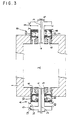
- Figures 2 to 6 show a furnace indicated 2 with a wall 1 and a burner system including a pair of regenerative burners A, B.
- These burners A, B each include an air supply duct 5 for supplying cool air, at room temperature, which opens directly into the furnace 2 and a fuel supply duct 3 arranged coaxially within the room-temperature supply duct 5 and opening through a flame stabiliser 4 into the furnace 2.
- the room temperature supply duct 5 are a plurality of ducts 6 for supplying preheated air at a high temperature, these opening directly into the furnace 2 through apertures separate from the room temperature supply outlet.
- the high temperature ducts 6 receive air through a common manifold 7 from a regenerative heating section, or regenerator, 10 which also surrounds the room temperature supply duct 5 and is packed with heat storage material 8, such as ceramic or metal balls, honeycomb, fins, meshes or any combination thereof; balls are shown by way of example in the drawings.
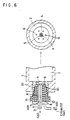
- the manifold 7 preferably tapers towards its respective outlets to the high temperature ducts 6 while the regenerative section 10 may also taper to its outlet to the manifold 7 as shown in the embodiment of Figure 6.
- the regenerative section 10 is preferably located at least partly within the furnace wall 1, as shown in the drawings.
- An inlet 11 for the heat storage material 8 may be provided, preferably at the top of the regenerator 10 and at a position remote from the furnace 2, as shown in Figure 6 while an outlet 12 for this material may be provided at the bottom.
- the room temperature supply duct 5 and the regenerator 10 of each regenerative burner A, B have adjacent air-inlet sections 13, 14 in which flow-switching means 9, such as a valve, operate to allow air to be introduced wholly or partially into the room temperature air supply duct 5 and into the regenerator 10.
- flow-switching means 9 such as a valve
- the regenerators 10 of the two regenerative burners A, B of the burner system are operated in alternation to supply preheated air to the furnace 2 to effect combustion of fuel supplied through a duct 3 and to receive hot exhaust products from the furnace to reheat their heat-storage material 8. More particularly, when fuel is introduced into the fuel supply duct 3 of the regenerative burner A (in combustion mode), it is mixed with the air injected through the room temperature air supply duct 5 near the flame stabiliser 4 and downstream thereof to initiate combustion. This combustion takes place with the fuel surrounded by fresh air and, since the furnace combustion products (an inert gas) are not mixed with the initial combustion mixture, the combustion is very stable and forms a stable flame region.
- the flame temperature is kept low.
- NOx production is inhibited and the fuel supply duct 3 and the flame stabiliser 4 are protected from deterioration due to high temperature oxidation.
- the remaining air necessary for complete fuel combustion is injected into the furnace 2 through the plurality of high temperature air supply ducts 6.
- the air is ejected from these ducts into the furnace at a high velocity and entrains the combustion products in the furnace before mixing with the fuel in the region of the stable flame formed adjacent the flame stabiliser 4 so as to sustain combustion.
- the flow-switching means 9 if present, is operated to stop the flow of air into the room temperature air supply duct 5, switching it completely to the regenerator inlet 14.
- air is fed solely through the heat storage material 8 and equilibrated in the manifold 7 before reaching the high temperature air supply ducts 6 to be injected into the furnace 2 where it interacts with the furnace gas.
- the air and entrained furnace gas then mix with the fuel which has been injected through the fuel supply duct 3 and which is no longer mixed with room temperature air: the fuel ignites spontaneously at the furnace temperature and combustion is sustained.
- the post-combustion exhaust gas in the furnace is discharged through the high temperature air supply ducts 6 of the regenerative burner B which is in exhaust mode, pre-heating its storage material 8.
- the above combustion and exhaust cycle is alternated through the regenerative burners A and B, for example at a rate of every tens of seconds to every several minutes.
- the temperature of the furnace 2 is kept sufficiently high, for example above about 800°C, combustion stability is ensured by the high temperature and it is not necessary to introduce any more air through the room temperature air supply ducts 5.
- the refractory materials used in ordinary burners to surround the flame are not required.
- the heat storage material 8 is partially or wholly located in the furnace wall, no refractory heat-insulating lining is required in the regenerator.
- Figures 4 and 5 show an embodiment of the present invention which does not use flow-switching means 9.
- fuel when fuel is introduced through the fuel supply duct 3 into the regenerative burner A, it is mixed with air supplied through the room temperature air supply duct 5 near the flame stabiliser 4 and downstream thereof to form a stable flame 18 in the furnace.
- the amount of room temperature air supplied is preferably small, accounting for less than 15% of the total air introduced into the furnace. The combustion caused by the small amount of room temperature air takes place at low temperatures.
- the major combustion reaction then takes place subsequently in the furnace 2 and is a slow combustion involving a large amount of furnace gas 16 before producing high furnace temperatures. This reduces the production of NOx effectively.
- the high temperature air heated by the heat storage material 8 is injected at a high velocity through the plurality of high temperature air supply ducts 6.
- the pre-heated air sucks in and mixes with a large amount of furnace combustion gas which results in a low oxygen partial pressure while combustion takes place; the flame is stabilised by slow combustion and low NOx forming combustion is sustained.
- the equipment of Figures 4 and 5 further includes a pilot burner supplied through a pilot duct 15 extending through the room temperature air supply duct 5 and terminating near the flame stabiliser 4.
- the room temperature air is injected continuously into the furnace 2 irrespective of whether the regenerative burner is in combustion mode or exhaust mode and the pilot burner and the flame stabiliser are therefore always cooled by the room temperature air and protected from deterioration due to high temperature oxidation.
- the pilot burner is located in a region in which the pressure fluctuation is very small so that a stable pilot flame can be formed.
- a flame detector 19 installed in the room temperature air supply duct 5 can give a cooling effect similar to that achieved by the pilot burner 15.
- this shows a regenerator 10 which, as mentioned above, is tapered toward the furnace.
- This enables the heat storage material 8 to be removed easily from the regenerator 10 simply by removal of the cover over the outlet 12 which allows the material to flow out.
- the cover of the outlet 12 is replaced and the cover of the inlet 11 is opened allowing the regenerator 10 to be packed easily with the heat storage material 8 even while the burners are installed in the furnace, without leaving any excessive spaces in the material.
- the regenerator 10 can be packed right to the top so that no channel is left here as in some prior art arrangements and the waste heat recovery is made much more efficient.
- the various embodiments of the present invention have a number of advantages.
- (1) The method results in the recirculation of furnace gas before any flames are generated in the furnace interior and while the continuous combustion occurs; as a result, no local hot spots are formed and NOx emission is kept at a low level.
- (2) A stabilised flame can be maintained with the use of a small amount of air at room temperature and this interacts with the furnace combustion gas before it encounters pre-heated, high temperature air in the furnace.
- the pre-heated high temperature air jets encounter and mix with the furnace combustion gas as the air is injected into the furnace which lowers the oxygen partial pressure.
- the combustion method of the present invention is not a two-stage combustion method which requires minor combustion in a primary combustion chamber prior to combustion in the furnace proper and therefore no such chamber is required, allowing the total structure to be reduced in size compared with prior art structures. Furthermore, since the stable flame is formed by cold air combustion with a small amount of room temperature air, the flame temperature is kept low and the flame stabiliser and the fuel supply duct outlet are protected from deterioration due to high temperature oxidation.
Landscapes
- Engineering & Computer Science (AREA)
- Chemical & Material Sciences (AREA)
- Combustion & Propulsion (AREA)
- Mechanical Engineering (AREA)
- General Engineering & Computer Science (AREA)
- Air Supply (AREA)
Applications Claiming Priority (9)
| Application Number | Priority Date | Filing Date | Title |
|---|---|---|---|
| JP188013/94 | 1994-08-10 | ||
| JP18801394 | 1994-08-10 | ||
| JP6188013A JPH0849836A (ja) | 1994-08-10 | 1994-08-10 | 蓄熱燃焼装置 |
| JP25368394 | 1994-10-19 | ||
| JP253683/94 | 1994-10-19 | ||
| JP6253683A JPH08121712A (ja) | 1994-10-19 | 1994-10-19 | 蓄熱燃焼方法及び装置 |
| JP314772/94 | 1994-12-19 | ||
| JP31477294A JP3397915B2 (ja) | 1994-12-19 | 1994-12-19 | リジェネレイティブバ−ナ装置 |
| JP31477294 | 1994-12-19 |
Publications (3)
| Publication Number | Publication Date |
|---|---|
| EP0696707A2 true EP0696707A2 (de) | 1996-02-14 |
| EP0696707A3 EP0696707A3 (de) | 1996-03-13 |
| EP0696707B1 EP0696707B1 (de) | 2001-07-04 |
Family
ID=27325982
Family Applications (1)
| Application Number | Title | Priority Date | Filing Date |
|---|---|---|---|
| EP95305433A Expired - Lifetime EP0696707B1 (de) | 1994-08-10 | 1995-08-03 | Regenerativ-Brenner Verbrennungssystem und Verbrennungsverfahren |
Country Status (3)
| Country | Link |
|---|---|
| EP (1) | EP0696707B1 (de) |
| CA (1) | CA2155173C (de) |
| DE (1) | DE69521572T2 (de) |
Cited By (1)
| Publication number | Priority date | Publication date | Assignee | Title |
|---|---|---|---|---|
| US11920786B2 (en) | 2017-11-06 | 2024-03-05 | Ngk Insulators, Ltd. | Regenerative burner, industrial furnace and method for producing a fired article |
Family Cites Families (4)
| Publication number | Priority date | Publication date | Assignee | Title |
|---|---|---|---|---|
| US4378205A (en) * | 1980-04-10 | 1983-03-29 | Union Carbide Corporation | Oxygen aspirator burner and process for firing a furnace |
| GB8618924D0 (en) * | 1986-08-02 | 1986-09-10 | Stordy Combustion Eng Ltd | Supply heat |
| DE59007772D1 (de) * | 1990-06-29 | 1995-01-05 | Wuenning Joachim | Verfahren und Vorrichtung zum Verbrennen von Brennstoff in einem Verbrennungsraum. |
| JPH081287B2 (ja) * | 1992-06-24 | 1996-01-10 | 中外炉工業株式会社 | 蓄熱式燃焼装置 |
-
1995
- 1995-08-01 CA CA002155173A patent/CA2155173C/en not_active Expired - Fee Related
- 1995-08-03 DE DE69521572T patent/DE69521572T2/de not_active Expired - Lifetime
- 1995-08-03 EP EP95305433A patent/EP0696707B1/de not_active Expired - Lifetime
Non-Patent Citations (1)
| Title |
|---|
| None |
Cited By (1)
| Publication number | Priority date | Publication date | Assignee | Title |
|---|---|---|---|---|
| US11920786B2 (en) | 2017-11-06 | 2024-03-05 | Ngk Insulators, Ltd. | Regenerative burner, industrial furnace and method for producing a fired article |
Also Published As
| Publication number | Publication date |
|---|---|
| EP0696707A3 (de) | 1996-03-13 |
| DE69521572T2 (de) | 2002-06-13 |
| CA2155173A1 (en) | 1996-02-11 |
| CA2155173C (en) | 1999-04-06 |
| DE69521572D1 (de) | 2001-08-09 |
| EP0696707B1 (de) | 2001-07-04 |
Similar Documents
| Publication | Publication Date | Title |
|---|---|---|
| RU2082915C1 (ru) | Способ сжигания топлива в камере сгорания и устройство для его осуществления | |
| EP0987508B1 (de) | Feuerungssystem für ein Kalzinationsverfahren mit Gegenstrom eines mineralischen Gutes | |
| EP1211458B1 (de) | Vormischbrenner mit niedrigem NOx-Ausstoss und Verfahren dafür | |
| CN100381755C (zh) | 具有辅助点火燃料喷管的分段燃烧系统 | |
| US4797087A (en) | Method and apparatus for generating highly luminous flame | |
| EP0432153B1 (de) | Vorrichtung und verfahren zur herstellung einer hochlichtgebenden flamme | |
| US2828813A (en) | Gas-fueled heating apparatus | |
| US5571006A (en) | Regenerative burner, burner system and method of burning | |
| JP3359284B2 (ja) | ガラス溶融炉内のNOxのエミッションを減少する方法 | |
| JPS62500044A (ja) | 復熱炉壁 | |
| CN101776260B (zh) | 一种水平移动式炉排气化炉 | |
| JP2013513084A (ja) | 製鋼施設用バーナー装置 | |
| CN105143804A (zh) | 一种端口回热炉 | |
| US4140480A (en) | Hot cupola gas burner | |
| KR20010114175A (ko) | 다공성 벽 로에서의 연소 | |
| EP0696707B1 (de) | Regenerativ-Brenner Verbrennungssystem und Verbrennungsverfahren | |
| RU2099661C1 (ru) | Способ сжигания природного газа в высокотемпературной промышленной печи | |
| JPH0611121A (ja) | 蓄熱式燃焼装置 | |
| CA2490637C (en) | Method and burner for rotary kilns | |
| JPH06241431A (ja) | 超低発熱量ガス燃焼装置 | |
| US1253342A (en) | Heat-developing apparatus. | |
| RU2813936C1 (ru) | Коаксиальная ступенчатая горелка факельного сжигания топливовоздушной смеси | |
| JP3305506B2 (ja) | 蓄熱燃焼装置 | |
| SU1520120A1 (ru) | Нагревательна печь | |
| US148531A (en) | Improvement in the modes and apparatus for utilizing waste gases |
Legal Events
| Date | Code | Title | Description |
|---|---|---|---|
| PUAI | Public reference made under article 153(3) epc to a published international application that has entered the european phase |
Free format text: ORIGINAL CODE: 0009012 |
|
| PUAL | Search report despatched |
Free format text: ORIGINAL CODE: 0009013 |
|
| AK | Designated contracting states |
Kind code of ref document: A2 Designated state(s): BE DE FR GB IT NL |
|
| AK | Designated contracting states |
Kind code of ref document: A3 Designated state(s): BE DE FR GB IT NL |
|
| 17P | Request for examination filed |
Effective date: 19960723 |
|
| 17Q | First examination report despatched |
Effective date: 19970707 |
|
| GRAG | Despatch of communication of intention to grant |
Free format text: ORIGINAL CODE: EPIDOS AGRA |
|
| RTI1 | Title (correction) |
Free format text: A REGENERATIVE BURNER COMBUSTION SYSTEM AND METHOD OF COMBUSTION |
|
| RTI1 | Title (correction) |
Free format text: A REGENERATIVE BURNER COMBUSTION SYSTEM AND METHOD OF COMBUSTION |
|
| GRAG | Despatch of communication of intention to grant |
Free format text: ORIGINAL CODE: EPIDOS AGRA |
|
| GRAH | Despatch of communication of intention to grant a patent |
Free format text: ORIGINAL CODE: EPIDOS IGRA |
|
| GRAH | Despatch of communication of intention to grant a patent |
Free format text: ORIGINAL CODE: EPIDOS IGRA |
|
| GRAA | (expected) grant |
Free format text: ORIGINAL CODE: 0009210 |
|
| AK | Designated contracting states |
Kind code of ref document: B1 Designated state(s): BE DE FR GB IT NL |
|
| REF | Corresponds to: |
Ref document number: 69521572 Country of ref document: DE Date of ref document: 20010809 |
|
| ITF | It: translation for a ep patent filed | ||
| ET | Fr: translation filed | ||
| REG | Reference to a national code |
Ref country code: GB Ref legal event code: IF02 |
|
| PLBE | No opposition filed within time limit |
Free format text: ORIGINAL CODE: 0009261 |
|
| STAA | Information on the status of an ep patent application or granted ep patent |
Free format text: STATUS: NO OPPOSITION FILED WITHIN TIME LIMIT |
|
| 26N | No opposition filed | ||
| PGFP | Annual fee paid to national office [announced via postgrant information from national office to epo] |
Ref country code: NL Payment date: 20130730 Year of fee payment: 19 Ref country code: DE Payment date: 20130731 Year of fee payment: 19 |
|
| PGFP | Annual fee paid to national office [announced via postgrant information from national office to epo] |
Ref country code: GB Payment date: 20130731 Year of fee payment: 19 Ref country code: FR Payment date: 20130808 Year of fee payment: 19 |
|
| PGFP | Annual fee paid to national office [announced via postgrant information from national office to epo] |
Ref country code: IT Payment date: 20130821 Year of fee payment: 19 |
|
| PGFP | Annual fee paid to national office [announced via postgrant information from national office to epo] |
Ref country code: BE Payment date: 20130819 Year of fee payment: 19 |
|
| REG | Reference to a national code |
Ref country code: DE Ref legal event code: R119 Ref document number: 69521572 Country of ref document: DE |
|
| REG | Reference to a national code |
Ref country code: NL Ref legal event code: V1 Effective date: 20150301 |
|
| GBPC | Gb: european patent ceased through non-payment of renewal fee |
Effective date: 20140803 |
|
| PG25 | Lapsed in a contracting state [announced via postgrant information from national office to epo] |
Ref country code: BE Free format text: LAPSE BECAUSE OF NON-PAYMENT OF DUE FEES Effective date: 20140831 Ref country code: NL Free format text: LAPSE BECAUSE OF NON-PAYMENT OF DUE FEES Effective date: 20150301 Ref country code: IT Free format text: LAPSE BECAUSE OF NON-PAYMENT OF DUE FEES Effective date: 20140803 |
|
| REG | Reference to a national code |
Ref country code: FR Ref legal event code: ST Effective date: 20150430 |
|
| REG | Reference to a national code |
Ref country code: DE Ref legal event code: R119 Ref document number: 69521572 Country of ref document: DE Effective date: 20150303 |
|
| PG25 | Lapsed in a contracting state [announced via postgrant information from national office to epo] |
Ref country code: DE Free format text: LAPSE BECAUSE OF NON-PAYMENT OF DUE FEES Effective date: 20150303 Ref country code: GB Free format text: LAPSE BECAUSE OF NON-PAYMENT OF DUE FEES Effective date: 20140803 |
|
| PG25 | Lapsed in a contracting state [announced via postgrant information from national office to epo] |
Ref country code: FR Free format text: LAPSE BECAUSE OF NON-PAYMENT OF DUE FEES Effective date: 20140901 |