EP0696811A1 - Fusible amélioré monté dans le thermostat d'un appareil électroménager - Google Patents
Fusible amélioré monté dans le thermostat d'un appareil électroménager Download PDFInfo
- Publication number
- EP0696811A1 EP0696811A1 EP95500119A EP95500119A EP0696811A1 EP 0696811 A1 EP0696811 A1 EP 0696811A1 EP 95500119 A EP95500119 A EP 95500119A EP 95500119 A EP95500119 A EP 95500119A EP 0696811 A1 EP0696811 A1 EP 0696811A1
- Authority
- EP
- European Patent Office
- Prior art keywords
- terminal
- thermostat
- strip
- box
- fitted
- Prior art date
- Legal status (The legal status is an assumption and is not a legal conclusion. Google has not performed a legal analysis and makes no representation as to the accuracy of the status listed.)
- Granted
Links
- 230000008018 melting Effects 0.000 claims description 3
- 238000002844 melting Methods 0.000 claims description 3
- 238000003466 welding Methods 0.000 claims 1
- 239000000463 material Substances 0.000 description 4
- 230000009471 action Effects 0.000 description 1
- 239000000919 ceramic Substances 0.000 description 1
- 239000004020 conductor Substances 0.000 description 1
- 230000008878 coupling Effects 0.000 description 1
- 238000010168 coupling process Methods 0.000 description 1
- 238000005859 coupling reaction Methods 0.000 description 1
- 230000004927 fusion Effects 0.000 description 1
- 230000006872 improvement Effects 0.000 description 1
- 239000011810 insulating material Substances 0.000 description 1
- 239000000155 melt Substances 0.000 description 1
- 239000002184 metal Substances 0.000 description 1
- 230000004048 modification Effects 0.000 description 1
- 238000012986 modification Methods 0.000 description 1
Images


Classifications
-
- H—ELECTRICITY
- H01—ELECTRIC ELEMENTS
- H01H—ELECTRIC SWITCHES; RELAYS; SELECTORS; EMERGENCY PROTECTIVE DEVICES
- H01H37/00—Thermally-actuated switches
- H01H37/002—Thermally-actuated switches combined with protective means
-
- H—ELECTRICITY
- H01—ELECTRIC ELEMENTS
- H01H—ELECTRIC SWITCHES; RELAYS; SELECTORS; EMERGENCY PROTECTIVE DEVICES
- H01H37/00—Thermally-actuated switches
- H01H37/74—Switches in which only the opening movement or only the closing movement of a contact is effected by heating or cooling
- H01H37/76—Contact member actuated by melting of fusible material, actuated due to burning of combustible material or due to explosion of explosive material
Definitions
- the present invention relates to a safety fuse for home electrical appliances of all kinds, fitted at one of the available thermostat terminals in order that when the thermostat stops working properly, either because the connections are welded together or the bimetallic strip is deformed or otherwise whatsoever, and the temperature of the appliance rises alarmingly, the conductor joined to the thermostat through the fuse will be broken off by fusion of the latter.
- such device In home electrical and appliances of any other kind whatsoever which require a safety thermal device, such device usually comprises a fuse mounted independently of the thermostat, i.e. connected to a terminal other than the thermostat terminals.
- One such device which is the least used and known as the minimet, is mounted inside an insulating ceramic box having a fixing plate.
- Devices of this kind work well but their high cost renders them rather unsuitable to be used in small appliances in which the end prices and hence profit margins are not very high.
- the device that is currently used most is mounted inside a cylindrically-shaped metal cartridge. This device costs less than the above-mentioned device but is shorter-lived and is moreover inconvenient in that if not suitably insulated dielectric strength problems ensue.
- the application of the system subject of the invention brings down the cost of the appliance and extends its life for it transmits the temperature at points that are far less critical than pure connection points.
- the present invention lies in the use of a safety fuse mounted at one of the thermostat connections, which fuse comprises an insulating box and a conducting strip that is welded at one end to the connection by means of a material that melts at a suitable temperature, whereas the other end stays free and constitutes a fast connection.
- the insulating box is made of a self-extinguishing material, is mounted directly on the thermostat terminal, and internally comprises two parallel channels that are respectively designed to house the two ends of the conducting strip.
- the upper channel houses the thermostat terminal and one of the ends of said strip, and thus for the two to be connected, the strip end is bent until it contacts the terminal and is then welded with a material having a suitable melting point.
- the lower channel houses the other end of the strip, that passes through the said channel to leave its end free for connection to be made as appropriate to the terminal used.
- the strip end welded to the thermostat terminal is therefore live, housed inside the insulating material box, and so when the weld is worn down by action of the heat the strips comes off the terminal and its end folds up to contact with the roof of the insulating plastic box, moving back to its initial position and hence breaking off the passage of current through it, ensuring that the appliance is switched off forthwith.
- Figure 1. Shows three views of a thermostat without the fuse subject of the invention.
- Figure 2. Shows three views of a thermostat with the fuse subject of the invention fitted.
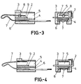
- Figure 3. Shows two cross-sections of the fuse subject of the invention, where it can be seen with the contact made.
- Figure 4.- Shows two cross-sections of the fuse subject of the invention, where it can be seen with the contact broken off.
- the fuse subject of the invention is arranged at one of the thermostat terminals and comprises a conducting strip and an insulating member (3), forming a sort of hollow box, with a mid-wall (4) that defines two parallel channels inside the box (3), an upper (5) and a lower (6) channel, for the said strip to be housed.
- This box (3) has a slot (9) designed to be fitted directly onto the terminal (2), the said terminal being arranged inside the upper channel (5) and slightly above the mid-wall (4), passing through the box (3) and ending (2) in an upwardly folded extension entwined about the box (3) locking it in such position.
- the conducting strip (7) is arranged inside the box (3), folded, as shown in figure 3, to achieve a better spring effect between its ends, and thus it defines a short end (7') and a long end (7'') with longitudinal grooves to make up a fast coupling.
- the long end (7'') of the strip (7) is housed in the lower channel (6) and passes through the same to leave its end free, thereby to allow an easy connection thereto.
- the short end (7') of the strip (7) is arranged inside the upper channel (5) and locked to the terminal by means of a weld (8) having a suitable melting point, thereby allowing the passage of current when the thermostat makes connection between terminal (1) and terminal (2).
Landscapes
- Fuses (AREA)
- Thermally Actuated Switches (AREA)
Applications Claiming Priority (2)
| Application Number | Priority Date | Filing Date | Title |
|---|---|---|---|
| ES9402202 | 1994-08-12 | ||
| ES9402202 | 1994-08-12 |
Publications (2)
| Publication Number | Publication Date |
|---|---|
| EP0696811A1 true EP0696811A1 (fr) | 1996-02-14 |
| EP0696811B1 EP0696811B1 (fr) | 1997-12-17 |
Family
ID=8287787
Family Applications (1)
| Application Number | Title | Priority Date | Filing Date |
|---|---|---|---|
| EP19950500119 Expired - Lifetime EP0696811B1 (fr) | 1994-08-12 | 1995-08-10 | Fusible amélioré monté dans le thermostat d'un appareil électroménager |
Country Status (2)
| Country | Link |
|---|---|
| EP (1) | EP0696811B1 (fr) |
| DE (1) | DE69501236T2 (fr) |
Citations (4)
| Publication number | Priority date | Publication date | Assignee | Title |
|---|---|---|---|---|
| US3611235A (en) * | 1970-07-01 | 1971-10-05 | American Thermostat Corp | Thermostat with built-in circuit breaker |
| DE2339674A1 (de) * | 1973-08-04 | 1975-02-20 | Thermostat & Schaltgeraetebau | Kombinierter temperaturregler mit schmelzmetallsicherung |
| GB1540088A (en) * | 1977-04-04 | 1979-02-07 | Beswick Ltd K | Fusible power resistors |
| US4720759A (en) * | 1986-05-15 | 1988-01-19 | Tobu Electric Co., Ltd. | Compact protector utilizing a bimetal and an excessive rise prevention portion |
-
1995
- 1995-08-10 DE DE1995601236 patent/DE69501236T2/de not_active Expired - Fee Related
- 1995-08-10 EP EP19950500119 patent/EP0696811B1/fr not_active Expired - Lifetime
Patent Citations (4)
| Publication number | Priority date | Publication date | Assignee | Title |
|---|---|---|---|---|
| US3611235A (en) * | 1970-07-01 | 1971-10-05 | American Thermostat Corp | Thermostat with built-in circuit breaker |
| DE2339674A1 (de) * | 1973-08-04 | 1975-02-20 | Thermostat & Schaltgeraetebau | Kombinierter temperaturregler mit schmelzmetallsicherung |
| GB1540088A (en) * | 1977-04-04 | 1979-02-07 | Beswick Ltd K | Fusible power resistors |
| US4720759A (en) * | 1986-05-15 | 1988-01-19 | Tobu Electric Co., Ltd. | Compact protector utilizing a bimetal and an excessive rise prevention portion |
Also Published As
| Publication number | Publication date |
|---|---|
| DE69501236D1 (de) | 1998-01-29 |
| EP0696811B1 (fr) | 1997-12-17 |
| DE69501236T2 (de) | 1998-04-30 |
Similar Documents
| Publication | Publication Date | Title |
|---|---|---|
| US3725972A (en) | Fire link and method of actuating same | |
| CN101563819B (zh) | 能插塞的过电压放电器 | |
| US6483420B1 (en) | Circuit breaker | |
| KR100948223B1 (ko) | 열 퓨즈를 가지는 유체 가열 기기 | |
| CN101770906B (zh) | 脱扣装置 | |
| US6184601B1 (en) | Thermally responsive protection apparatus | |
| GB2290169A (en) | Double safety thermostat | |
| AU6172099A (en) | Thermal fuse | |
| JPH0145931B2 (fr) | ||
| CN1988284B (zh) | 和电流输出端连接的安全插座 | |
| US4885560A (en) | Thermal relay | |
| EP1513172B1 (fr) | Interrupteur de coupure de courant continu | |
| JP3568824B2 (ja) | 回路遮断装置 | |
| EP0696811B1 (fr) | Fusible amélioré monté dans le thermostat d'un appareil électroménager | |
| JP4128250B2 (ja) | 電源用サーマルプロテクタ | |
| CN219046544U (zh) | 一种ptc加热器过流保护装置 | |
| DE10032888B4 (de) | Schaltkreisunterbrecher | |
| EP0573430B1 (fr) | Element de chauffage electrique tubulaire avec un regulateur de temperature | |
| TWI275224B (en) | Circuit protector of dual temperature sensing cutoff | |
| JPH05234496A (ja) | 回路遮断制御装置 | |
| EP0259926A1 (fr) | Fusible | |
| CN215527583U (zh) | 一种新型结构热保护器 | |
| EP1180844B1 (fr) | Appareil de protection thermosensible pour moteurs électriques | |
| CN101165836B (zh) | 温度保险丝连接结构 | |
| CN213277992U (zh) | 控制柜熔断保护器 |
Legal Events
| Date | Code | Title | Description |
|---|---|---|---|
| PUAI | Public reference made under article 153(3) epc to a published international application that has entered the european phase |
Free format text: ORIGINAL CODE: 0009012 |
|
| AK | Designated contracting states |
Kind code of ref document: A1 Designated state(s): DE FR IT PT |
|
| 17P | Request for examination filed |
Effective date: 19960322 |
|
| GRAG | Despatch of communication of intention to grant |
Free format text: ORIGINAL CODE: EPIDOS AGRA |
|
| 17Q | First examination report despatched |
Effective date: 19970411 |
|
| GRAG | Despatch of communication of intention to grant |
Free format text: ORIGINAL CODE: EPIDOS AGRA |
|
| GRAG | Despatch of communication of intention to grant |
Free format text: ORIGINAL CODE: EPIDOS AGRA |
|
| GRAH | Despatch of communication of intention to grant a patent |
Free format text: ORIGINAL CODE: EPIDOS IGRA |
|
| GRAH | Despatch of communication of intention to grant a patent |
Free format text: ORIGINAL CODE: EPIDOS IGRA |
|
| GRAA | (expected) grant |
Free format text: ORIGINAL CODE: 0009210 |
|
| AK | Designated contracting states |
Kind code of ref document: B1 Designated state(s): DE FR IT PT |
|
| REF | Corresponds to: |
Ref document number: 69501236 Country of ref document: DE Date of ref document: 19980129 |
|
| ET | Fr: translation filed | ||
| ITF | It: translation for a ep patent filed | ||
| REG | Reference to a national code |
Ref country code: PT Ref legal event code: SC4A Free format text: AVAILABILITY OF NATIONAL TRANSLATION Effective date: 19980310 |
|
| PLBE | No opposition filed within time limit |
Free format text: ORIGINAL CODE: 0009261 |
|
| STAA | Information on the status of an ep patent application or granted ep patent |
Free format text: STATUS: NO OPPOSITION FILED WITHIN TIME LIMIT |
|
| 26N | No opposition filed | ||
| PGFP | Annual fee paid to national office [announced via postgrant information from national office to epo] |
Ref country code: PT Payment date: 20020722 Year of fee payment: 8 |
|
| PGFP | Annual fee paid to national office [announced via postgrant information from national office to epo] |
Ref country code: DE Payment date: 20020827 Year of fee payment: 8 |
|
| PGFP | Annual fee paid to national office [announced via postgrant information from national office to epo] |
Ref country code: FR Payment date: 20020830 Year of fee payment: 8 |
|
| PG25 | Lapsed in a contracting state [announced via postgrant information from national office to epo] |
Ref country code: PT Free format text: LAPSE BECAUSE OF NON-PAYMENT OF DUE FEES Effective date: 20040229 |
|
| PG25 | Lapsed in a contracting state [announced via postgrant information from national office to epo] |
Ref country code: DE Free format text: LAPSE BECAUSE OF NON-PAYMENT OF DUE FEES Effective date: 20040302 |
|
| PG25 | Lapsed in a contracting state [announced via postgrant information from national office to epo] |
Ref country code: FR Free format text: LAPSE BECAUSE OF NON-PAYMENT OF DUE FEES Effective date: 20040430 |
|
| REG | Reference to a national code |
Ref country code: PT Ref legal event code: MM4A Free format text: LAPSE DUE TO NON-PAYMENT OF FEES Effective date: 20040229 |
|
| REG | Reference to a national code |
Ref country code: FR Ref legal event code: ST |
|
| PG25 | Lapsed in a contracting state [announced via postgrant information from national office to epo] |
Ref country code: IT Free format text: LAPSE BECAUSE OF NON-PAYMENT OF DUE FEES Effective date: 20050810 |