EP0696877B1 - Verfahren und Einrichtung zur Steuerung von Empfangsunterbrechungen in Funkgeräten - Google Patents
Verfahren und Einrichtung zur Steuerung von Empfangsunterbrechungen in Funkgeräten Download PDFInfo
- Publication number
- EP0696877B1 EP0696877B1 EP95112402A EP95112402A EP0696877B1 EP 0696877 B1 EP0696877 B1 EP 0696877B1 EP 95112402 A EP95112402 A EP 95112402A EP 95112402 A EP95112402 A EP 95112402A EP 0696877 B1 EP0696877 B1 EP 0696877B1
- Authority
- EP
- European Patent Office
- Prior art keywords
- error
- signal
- detecting
- radio
- detected
- Prior art date
- Legal status (The legal status is an assumption and is not a legal conclusion. Google has not performed a legal analysis and makes no representation as to the accuracy of the status listed.)
- Expired - Lifetime
Links
- 238000000034 method Methods 0.000 title claims description 40
- 238000001514 detection method Methods 0.000 claims description 27
- 230000004044 response Effects 0.000 claims description 9
- 238000007493 shaping process Methods 0.000 claims description 6
- 230000002401 inhibitory effect Effects 0.000 claims description 5
- 230000009471 action Effects 0.000 description 21
- 230000008569 process Effects 0.000 description 20
- 230000008859 change Effects 0.000 description 4
- 238000010586 diagram Methods 0.000 description 3
- 230000005540 biological transmission Effects 0.000 description 1
- 230000000694 effects Effects 0.000 description 1
- 230000004048 modification Effects 0.000 description 1
- 238000012986 modification Methods 0.000 description 1
Images


Classifications
-
- H—ELECTRICITY
- H04—ELECTRIC COMMUNICATION TECHNIQUE
- H04W—WIRELESS COMMUNICATION NETWORKS
- H04W52/00—Power management, e.g. Transmission Power Control [TPC] or power classes
- H04W52/02—Power saving arrangements
- H04W52/0209—Power saving arrangements in terminal devices
- H04W52/0225—Power saving arrangements in terminal devices using monitoring of external events, e.g. the presence of a signal
- H04W52/0229—Power saving arrangements in terminal devices using monitoring of external events, e.g. the presence of a signal where the received signal is a wanted signal
-
- H—ELECTRICITY
- H04—ELECTRIC COMMUNICATION TECHNIQUE
- H04W—WIRELESS COMMUNICATION NETWORKS
- H04W88/00—Devices specially adapted for wireless communication networks, e.g. terminals, base stations or access point devices
- H04W88/02—Terminal devices
- H04W88/022—Selective call receivers
-
- Y—GENERAL TAGGING OF NEW TECHNOLOGICAL DEVELOPMENTS; GENERAL TAGGING OF CROSS-SECTIONAL TECHNOLOGIES SPANNING OVER SEVERAL SECTIONS OF THE IPC; TECHNICAL SUBJECTS COVERED BY FORMER USPC CROSS-REFERENCE ART COLLECTIONS [XRACs] AND DIGESTS
- Y02—TECHNOLOGIES OR APPLICATIONS FOR MITIGATION OR ADAPTATION AGAINST CLIMATE CHANGE
- Y02D—CLIMATE CHANGE MITIGATION TECHNOLOGIES IN INFORMATION AND COMMUNICATION TECHNOLOGIES [ICT], I.E. INFORMATION AND COMMUNICATION TECHNOLOGIES AIMING AT THE REDUCTION OF THEIR OWN ENERGY USE
- Y02D30/00—Reducing energy consumption in communication networks
- Y02D30/70—Reducing energy consumption in communication networks in wireless communication networks
Definitions
- the present invention relates to an apparatus and a method for controlling an intermittent reception time in radio equipment and particularly to an apparatus and a method for controlling an intermittent reception time in a selective-calling receiver.
- Radio equipment of this kind for example, a selective-calling receiver (hereinafter referred to as a receiver) receives a radio signal composed of plural frames.
- Each frame includes plural code words each of which a synchronizing signal or an identification number is assigned to.
- a predetermined own identification number is assigned to a receiver in advance; and a received identification signal coinciding with a predetermined own identification number is inserted into some code words of some frames.
- a frame containing a code word having an identification signal inserted in it which coincides with the own identification number is called a self-frame.
- the receiver supplies power to its radio circuit at the time to receive its self-frame, but does not supply power to the radio circuit when receiving any frame other than the self-frame.
- This power supply control system is called an intermittent reception system, which can make longer lifetime of the battery used in it.
- a receiver for making such an intermittent reception as this is described for example in Japan Patent Application Laid-open Heisei 4-213229.
- This receiver is provided with a reference clock generator for generating a reference clock and a counter for counting the reference clock.
- the receiver judges a time to receive a synchronizing signal in its self-frame by counting the reference clock with the counter, turns on the radio circuit at the time, and receives the synchronizing signal.
- a receiver which receives a radio signal having a long period in transmission of frames has a long period in reception of self-frames and also has a long period in reception of synchronizing signals. Therefore, when the reference clock generator is poor in accuracy, difference between a count value of the counter and a time to receive a frame containing a synchronizing signal is great.
- the receiver compensates the value of one period of the intermittent receiving action by compensating a count value of the counter when detecting a synchronizing signal.
- the receiver surely receives its self-frame by adjusting the time to receive a synchronizing signal of the next self-frame with a time corresponding to the detected error as disclosed for instance in US Patent Application US 5 309 153.
- the receiver described above compensates the value of one period of the intermittent receiving action each time a synchronizing signal contained in a self-frame is detected, the receiver has a problem that its power consumption is made greater and its battery life is made shorter in comparison with a receiver not making such compensation as this.
- the receiver of this patent application varies greatly in count values of the counter when the reference clock frequency coming from the reference clock generator is greatly changed because of a sudden change in the temperature. Therefore, since the receiver, which detects an error between a count value and a code word each time a synchronizing signal is detected, also detects a synchronization error between a suddenly changed count value and a code word and adjusts a point of time to receive a self-frame, it may incorrectly adjust a point of time to receive the next self-frame.
- An object of the invention is to provide an apparatus and a method for controlling an intermittent reception time in radio equipment which makes longer lifetime of the battery used in it.
- Another object of the invention is to provide an apparatus and a method for controlling an intermittent reception time which can correctly adjust a point of time to receive a self-frame even in case that a count value of its counter is suddenly changed.
- Another object of the invention is to provide an apparatus and a method for controlling an intermittent reception time which adjusts a point of time to receive a frame assigned to the radio equipment when a synchronization error between a count value of the counter and a code word of a radio signal is consecutively detected at a predetermined number of times.
- An apparatus for controlling an intermittent reception time in radio equipment of the invention is provided with an oscillator for generating a reference clock, a counter for counting the reference clock, a receiving circuit which receives a radio signal composed of plural frames and outputs the received signal, a synchronizing signal detecting means for detecting a synchronizing signal out of the received signal, a detector for detecting an error between a word value of the received signal and a count value of the counter in response to detection of the synchronizing signal, and an adjusting circuit which adjusts a margin time for starting the receiving circuit to receive a frame assigned to the receiver in case that the detector has consecutively detected the error at a predetermined number of times.
- the apparatus may be also provided with an inhibiting circuit which inhibits the detecting circuit from making an error detection after a margin time for starting the receiving circuit has been adjusted by the adjusting circuit.
- a controlling method for controlling an intermittent reception time in radio equipment of the invention is provided with a process of supplying power to a receiving circuit for receiving a radio signal, a detecting a synchronizing signal out of the radio signal, a judging whether or not a compensation value to be used for adjusting a point of time to supply power to the receiving circuit has been stored in a compensation value storing circuit, setting a point of time to supply power to the receiving circuit on the basis of a compensation value when the compensation value has been stored in the compensation value storing circuit, of detecting an error between the radio signal and a count value of the internal counter of the selective-calling radio receiver when no compensation value has been stored in the compensation value storing circuit, judging whether or not an already stored error exists in response to detection of an error, storing the detected error in an error storing circuit when no already stored error exists, judging whether or not a detected error coincides with an already stored error when the already stored error exists in the error storing circuit, rewriting an error stored in the error storing circuit with a detected error when
- the controlling method of the invention may be also provided with a inhibiting detection of an error between a radio signal and a count value of the internal counter of the radio equipment after storing a compensation value into the compensation value storing circuit.
- the apparatus or method according to the invention adjusts a margin time for starting the receiving circuit to receive a frame assigned to the receiver on the basis of an error between a word value of a received signal and a count value of the counter when the error is consecutively detected at a predetermined number of times. Therefore, even when a count value of the counter is suddenly changed because of a sudden change in the temperature or the like, the invention makes it possible to exactly adjust a margin time for starting the receiving circuit without adjusting the margin time for starting the receiving circuit on the basis of an error at this time between the count value of the counter and the word value of the received signal.
- the invention inhibits detection of an error between a radio signal and a count value of the counter or internal counter of the radio equipment after storing a compensation value in a memory or after adjusting a margin time for starting a receiving circuit by means of an adjusting circuit, lifetime of the battery used in it can be made longer.
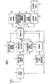
- Figure 1 is a functional block diagram of a selective-calling receiver showing an embodiment of the invention.
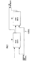
- Figure 2 is a functional block diagram of the counter shown in Figure 1.
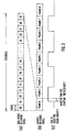
- Figures 3(a) and 3(b) show a signal format showing an example of signals used in the embodiment.
- Figure 3(c) is a timing chart for explaining a margin time for starting the radio circuit shown in Figure 1 to receive a self-frame.
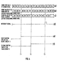
- Figure 4(a) shows code words having the signal format shown in Figure 3(a).
- Figures 4(b) and 4(c) shows count values of the word counter shown in Figure 2.
- Figure 4(d) is a timing chart of an interrupt signal outputted from the synchronizing signal detector to the controller shown in Figure 1.
- Figures 4(e) and 4(f) are timing charts for explaining the first starting time and the second starting time to start the radio circuit shown in Figure 1.
- Figures 5(a) and 5(b) show code words and frames having the signal format shown in Figures 3(a) and 3(b).
- Figure 5(c) shows count values of the word counter shown in Figure 2.
- Figure 5(d) is a timing chart for explaining an on-off action of the radio circuit shown in Figure 1.
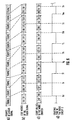
- Figures 6(a) and 6(b) shows code words and frames having the signal format shown in Figures 3(a) and 3(b).
- Figure 6(c) shows count values of the word counter shown in Figure 2.
- Figure 6(d) is a timing chart for explaining an on-off action of the radio circuit shown in Figure 1.
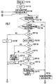
- Figure 7 is a flowchart for explaining a method for setting a point of time to start the radio circuit shown in Figure 1.
- Figure 8 is a flowchart for explaining another embodiment having another method for setting a point of time to start the radio circuit shown in Figure 1.
- an antenna 1 receives a radio signal and outputs the received signal.
- a radio circuit 2 is controlled in an on-off mode by a radio circuit controlling signal from a controller 9.
- the radio circuit 2 amplifies the received signal, demodulates the amplified received signal, and outputs the demodulated signal.
- a waveform shaping circuit 3 outputs a digital signal obtained by shaping waveform of the demodulated signal to a synchronizing signal detector 4 and a coincidence detector 6.
- the synchronizing signal detector 4 which is controlled in an on-off mode by the controller 9, detects a synchronizing signal out of the digital signals.
- the synchronizing signal detector 4 When detecting a word synchronizing signal out of a synchronizing signal contained in a self-frame, the synchronizing signal detector 4 outputs a synchro-detection signal to the controller 9. And the synchronizing signal detector 4 outputs a synchro-establishment signal to a counter 8 through responding to detection of a word synchronizing signal and a frame synchronizing signal out of a synchronizing signal.
- An identification number memory 5 outputs a predetermined own identification number at an address specified by the controller 9 to the coincidence detector 6.
- the coincidence detector 6, which is controlled in an on-off mode by the controller 9, detects an identification signal out of the digital signals.
- the coincidence detector 6 judges whether or not the detected identification signal and the predetermined own identification number obtained from the identification number memory 5 coincide with each other.
- the coincidence detector 6 outputs a coincidence signal to the controller 9 in case of coincidence of both of them, but outputs no signal in case of no coincidence of them.
- a reference clock generator 7 generates a reference clock and supplies it to the counter 8.
- the counter 8 counts the reference clock and compensates its count value by means of input of a synchro-establishment signal from the synchronizing signal detector 4.
- the controller 9 responds to a synchro-detection signal from the synchronizing signal detector 4, detects an error between a count value of the counter 8 and a code word value and frame value of a received radio signal, and stores the detected error Z as an error Z0 in an error memory 10.
- the controller 9 judges whether or not the error Z0 stored in the error memory 10 has been consecutively detected at k times where k is the number of times stored in a number-of-consecutive-error-occurrences memory 11, and stores the error Z0 as a compensation value Z1 in a compensation value memory 12 when the error Z0 has been consecutively detected at k times.
- the controller 9 judges whether or not the compensation value Z1 is stored in the compensation'value memory 12, and turns on the radio circuit 2 by supplying a radio circuit controlling signal to the radio circuit 2 at a point of time as described later on the basis of this judgement and a count value of the counter 8.
- the controller 9 outputs an alarting-driver signal to an alarting driver 13 in response to a cooncidence signal from the coincidence detector 6, and turns off the radio circuit 2 by supplying a radio circuit controlling signal to the radio circuit 2 after outputting the alarting driver signal. And the controller 9 turns off the radio circuit 2 by supplying a radio circuit controlling signal to the radio circuit 2 when inputting no coincidence signal from the coincidence detector 6 by the time when reception of a self-frame is finished.
- the error memory 10, the number-of-consecutive-error-occurrences memory 11, and the compensation value memory 12 are composed of RAM's.
- the error memory 10 stores an error Z0 from the controller 9 in it and outputs the stored error Z0 to the controller 9 according to an instruction from the controller 9.
- the number-of-consecutive-error-occurrences memory 11 stores the number k of consecutive error occurrences as described above in it and outputs the stored number k of consecutive error occurrences to the controller 9 according to an instruction from the controller 9.
- the compensation value memory 12 stores a compensation value Z1 from the controller 9 in it and outputs the stored compensation value Z1 to the controller 9 according to an instruction from the controller 9.
- the alarting driver 13 outputs an alarting signal in response to a alarting driver signal.
- An alarting circuit 14 makes an alarting operation in response to the alarting signal.
- the counter 8 is provided with a word counter 801 and a frame counter 802.
- the word counter 801 counts codes 00 to 99 corresponding to code words of one frame through input of the reference clock from the reference clock generator 7.
- the frame counter 802 counts frames 0 to 8 corresponding to frame values of one sequence in linkage with a carry of the word counter 801.
- a synchro-establishment signal from the synchronizing signal detector 4 is inputted into the word counter 801 and the frame counter 802
- their count values are respectively set as a word value and a frame value which have been predetermined and contain a word synchronizing signal. In this manner, a word synchronization and a frame synchronization are established.
- the count values of the word counter 801 and the frame counter 802 are supplied to the controller 9.
- Figure 3(a) shows code words contained in one of frames composing a radio signal
- Figure 3(b) shows frames of the radio signal
- Figure 3(c) shows a margin time for starting the radio circuit 2.
- one sequence of a radio signal is composed of nine frames 0 to 8 and each frame is composed of 100 code words 00 to 99.
- a synchronizing signal is composed of a word synchronizing signal, a frame synchronizing signal, and a frame information signal, and for example a word synchronizing signal is contained in code words 00 to 01.
- a frame synchronizing signal is contained in code words 02 to 04 and a frame information signal is contained in code words 05 to 08.
- An identification signal is contained in code words on and after code word 09.
- frames 1, 4, and 7 are frames assigned to a receiver.
- the receiver starts the radio circuit 2 at a point of time earlier than the time to receive a frame assigned to the receiver itself.
- Figure 4(a) shows code words composing one frame
- Figures 4(b) and 4(c) show count values of the word counter 801, respectively, before and after establishing synchronization
- Figure 4(d) shows a point of time for the synchronizing signal detector 4 to output a synchronization detecting signal when detecting a word synchronizing signal
- Figures 4(e) and 4(f) show points of time to start the radio circuit 2.
- the count value of the word counter 801 after establishing synchronization as.shown in Figure 4(c) is set as code word 02 to which a word synchronizing signal has been in advance assigned when inputting the synchronizing signal shown in Figure 4(d) into the controller 9, namely, when establishing a word synchronization at the time T3.
- the radio circuit 2 when the first starting time to start the radio circuit 2, namely, a point of time to start the radio circuit 2 on the basis of a compensation value Z1 stored in the compensation value memory 12 has not been adjusted, the radio circuit 2 is started at the time T1 when the frame counter 802 counts a frame which is one frame before a self-frame and the count value of the word counter 801 becomes 88 in consideration of an expectable maximum error so that the radio circuit 2 may surely receive a synchronizing signal. In this embodiment, the radio circuit 2 is started at a point of time when a count value of the word counter 801 is eight code words earlier than the synchronizing signal.
- the radio circuit 2 when the second starting time to start the radio circuit 2, namely, a point of time to start the radio circuit 2 on the basis of the compensation value Z1 is set, the radio circuit 2 is started at the time T2, for example, when the frame counter 802 counts a frame which is one frame before a self-frame and the count value of the word counter 801 becomes 92 in consideration of property of an error between the reference clock outputted from the reference clock generator 7 and the code words.
- the receiver stores this error as a compensation value Z1, and after judging this as an error to the radio signal depending upon accuracy of the reference clock generator 7, the receiver starts the radio circuit 2 as considering a count value corresponding to the compensation value Z1 as a margin time for starting the radio circuit 2.
- the second starting time to start the radio circuit 2 improves a battery saving effect by a time of (T2 - T1).
- the number k of consecutive error occurrences stored in the number-of-consecutive-error-occurrences memory 11 is set as 2.
- the receiver When the radio circuit 2 is started by turning power on, the receiver receives a radio signal through the antenna 1 and amplifies it, demodulates it, and shapes its waveform by means of the radio circuit 2 and the waveform shaping circuit 3. The receiver detects a word synchronizing signal contained in a synchronizing signal by means of the synchronizing signal detector 4.
- the synchronizing signal detector 4 outputs a synchro-detection signal to the controller 9 when detecting a word synchronizing signal from code words 00 to 01 of a self-frame 7 ( Figure 5(b)). In response to this, the controller 9 detects a count value 68 of the word counter 802 at the time Tb ( Figure 5(c)).
- the synchronizing signal detector 4 After outputting the synchro-detection signal, the synchronizing signal detector 4 outputs a synchro-establishment signal to the word counter 802 and establishes a word synchronization immediately after the time Tb. By this operation, the count value of the word counter 802 is changed from 68 to 02 to be equal to the code word value of the radio signal.
- the synchronizing signal detector 4 detects a frame synchronizing signal following the word synchronizing signal and detects that the code word being currently received is frame 7 on the basis of a fact that this frame. synchronizing signal shows the frame 7. By this detection the synchronizing signal detector 4 outputs a synchro-establishment signal to the counter 8, sets a count value of the frame counter 802 as "0", and establishes a frame synchronization with the radio signal.
- the coincidence detector 6 reads the own identification call number addressed by the controller 9 from the identification number memory 5 and compares it with an identification signal at the time Tc. In case that both of them coincide with each other in this comparison, the coincidence detector 6 outputs a coincidence signal to the alarting driver 13. In response to this alarting driver signal, the alarting driver 13 outputs an alarting signal and the paging circuit 14 makes an alarting operation. In case that a coincidence signal is not inputted into the controller 9 even after a frame assigned to the receiver itself has finished to be received, the controller 9 outputs a radio circuit controlling signal and turns off the radio circuit 2 ( Figure 5(d)).
- the word counter 801 After synchronization between the counter 8 and a radio signal has been established, the word counter 801 begins counting the reference clock sent from the reference clock generator 7 with a count value 02. When the word counter 801 counts up to 99, its count value returns to 00 and at the same time a count value of the frame counter 802 becomes 8 from 7 because of a carry. Still after this, the word counter 801 keeps counting the reference clock and the controller 9 detects the first starting time to start the radio circuit 2, namely, the time when a count value of the word counter 801 becomes 88 and a count value of the frame counter 802 becomes 0, and the controller 9 starts the radio circuit 2 at the time Td.
- a radio signal is inputted into the synchronizing signal detector 4 turned on by the controller 9 through the antenna 1, the radio circuit 2, and the waveform shaping circuit 3.
- the synchronizing signal detector 4 After outputting a synchro-detection signal, the synchronizing signal detector 4 sets a count value of the word counter 801 as 02 immediately after the time Te and establishes a word synchronization.
- the synchronizing signal detector 4 detects a frame detecting signal, sets a count value of the frame counter 802 as 01 immediately after the time Te, and establishes a frame synchronization. In Figure 5, though not shown, an error between a count value and a frame value of the frame counter 802 does not occur.
- the controller 9 After establishing a frame synchronization, the controller 9 turns off the synchronizing signal detector 4 and turns on the coincidence detector 6.
- the coincidence detector 6 reads the own identification number addressed by the controller 9 from the identification number memory 5 and compares it with an identifidation signal at the time Tf. In case that both of them coincide with each other in this comparison, the coincidence detector 6 outputs a coincidence signal to the alarting driver 13.
- the alarting driver 13 In response to this alarting driver signal, the alarting driver 13 outputs an alarting signal and the alarting circuit 14 makes an alarting operation.
- the controller 9 In case that a coincidence signal is not inputted into the controller 9 even after a frame assigned to the receiver itself has finished to be received, the controller 9 outputs a radio circuit controlling signal and turns off the radio circuit 2.
- the controller 9 After judging that the detected identification sitnal and the own identification number coincide with each other, the controller 9 outputs a radio circuit controlling signal and turns off the radio circuit 2.
- the receiver In receiving a frame assigned to the receiver itself at the next time, namely, in receiving the frame 4, the receiver starts the radio circuit 2 at the time Tg, when a count value of the frame counter is 3 and a count value of the word counter is 88 at the time to start the radio circuit 2 equivalent to the time to receive the frame 1.
- the controller 9 starts the radio circuit 2 when the word counter 801 counts 95 and the frame counter 802 counts a value which is one frame before the self-frame to receive.
- Figures 6(a) to 6(d) are timing charts for explaining a starting operation of the radio circuit 2 showing an embodiment of the invention, respectively, in the same manner as Figures 5(a) to 5(d), where the number k of consecutive occurrences of an error is set as 2 in the same manner as Figures 5(a) to 5(d). While Figures 5(a) to 5(d) explain a case that errors detected by the controller 9 for the first time and the second time are equal to each other, Figures 6(a) to 6(d) show a case that the first detected error and the second detected error are different from each other and the second detected error and the third detected error coincide with each other.
- the time to start the radio circuit 2 for receiving a self-frame for the first time, namely, for receiving frame 1 is the time Td when a count value of the word counter 801 is 88 and a count value of the frame counter 802 is 0.
- Reception of the next frame 4 is made at the time Tg when a count value of the word counter 801 is 88 and a count value of the frame counter 802 is 3.
- the controller 9 reads the number k of consecutive occurrences of an error having the same value which is stored in the number-of-consecutive-error-occurrences memory 11 and compares the number k with the number of consecutive occurrences of the error Z having the same value.
- the receiver of this embodiment can start the radio circuit 2 by means of the controller 9 on the basis of a compensation value Z1 stored in the compensation value memory 12, but the receiver can be also made so that data stored in the compensation value memory 12 may not be eliminated even when the power of the receiver is turned off and the radio circuit 2 may be started on the basis of the compensation value Z1 when power is turned on at the next time.
- This first intermittent receiving action means an intermittent receiving action where the radio circuit 2 is started at the above-mentioned first starting time of the radio circuit 2 when the intermittent receiving action is finished.
- Step 104 When the radio circuit 2 is started at the first starting time, the receiver makes a detection of a synchronizing signal (Step 104). When no synchronizing signal is detected, the receiver returns to a process of Step 104.
- the controller 9 makes a detection of an error Z (Step 108).
- Step 112 the controller 9 judges whether or not the value Z0 stored in the error memory 10 coincides with the detected error Z.
- the controller 9 proceeds to a process of the above-mentioned Step 110.
- the controller 9 increments the internal flag I by 1 (Step 113) and judges whether or not a value of "I - 1" in relation with the internal flag I and the number k of consecutive occurrences of an error stored in the number-of-consecutive-error-occurrences memory 11 coincide with each other (Step 114).
- the controller 9 When they coincide with each other, the controller 9 writes an error Z at this time as a compensation value Z1 into the compensation value memory 12 (Step 115) and performs the above-mentioned second intermittent receiving action (Step 116). And after this second intermittent receiving action, the controller 9 starts the radio circuit 2 at the second starting time of the radio circuit 2 and proceeds to a process of Step 104. On the other hand, when both of them do not coincide with each other in a process of Step 114, the controller 9 proceeds to a process of the above-mentioned Step 103 and repeats this action until a compensation value Z1 is stored in the compensation value memory 12.
- Step 105 when a compensation value Z1 is stored in the compensation value memory 12 in a process of Step 105, the controller 9 proceeds to a process of the above-mentioned Step 116.
- the second embodiment makes a detection of an error Z even after a compensation value Z1 is stored in the compensation value memory 12, and rewrites the compensation value Z1 at any time.
- the receiver makes a detection of a synchronizing signal (Step 204). When no synchronizing signal is detected, the receiver returns to a process of Step 204.
- Step 212 the controller 9 performs the second intermittent receiving action on the basis of the stored compensation value Z1 (Step 212) and proceeds to a process of the above-mentioned Step 204.
- the controller 9 proceeds to a process of the above-mentioned Step 211, and when they coincide with each other, the controller 9 stores the error Z as a compensation value Z1 in the compensation value memory 12 (Step 216), and then proceeds to a process of the above-mentioned Step 212.
- the embodiment shown in Figure 8 continues a detecting action of an error Z even after a compensation value Z1 has been stored in the compensation value memory 12. And even if the value of error Z is changed in the middle of a receiving process, unless the changed value is consecutively repeated by a predetermined number of times k, this embodiment starts the radio circuit 2, keeping a margin time for starting the radio circuit 2 as the same value as the last receiving action. And if the changed value is repeated consecutively at k times, each time it is, the controller 9 determines the starting time of the radio circuit 2 for receiving the next self-frame. Therefore, this embodiment makes it possible to dynamically compensate a frame length to some degree.
- the invention makes it possible to not only compensate a frame length in words but also detect an error between a radio signal and a count value in bits and compensate the starting time of the radio circuit 2 in bits.
- the invention can be applied to any system which has a signal format for a selective-calling receiver of any system such as a POCSAG, ERMES, or NTT system.
- an apparatus and a method for controlling an intermittent reception time of a radio equipment detect a synchronization error between a count value of the word counter and a code word of a radio signal, judge that the detected error is definite only in case that it occurs consecutively at a predetermined number of times, and compensate a margin time for starting the radio circuit. Therefore, even in case that the reference clock from the reference clock generator is greatly changed in frequency and a count value of the word counter is greatly changed because of a sudden change in the temperature, the invention does not set. the time to receive a self-frame on the basis of such a sudden change in the count value as this and therefore the invention can correctly set the time to receive the self-frame.
- an intermittent receiving circuit and an intermittent receiving method of a selective-calling receiver can reduce the power consumption, since they compensate a margin time for starting the radio circuit when a detected error occurs consecutively at a predetermined number of times and make no error detection after this compensation.
- the invention can be applied to any radio equipment which establishes synchronization with a radio signal and makes an intermittent receiving action.
Landscapes
- Engineering & Computer Science (AREA)
- Computer Networks & Wireless Communication (AREA)
- Signal Processing (AREA)
- Mobile Radio Communication Systems (AREA)
- Synchronisation In Digital Transmission Systems (AREA)
- Circuits Of Receivers In General (AREA)
Claims (9)
- Einrichtung zum Steuern von Empfangsunterbrechungen in Funkgeräten, mit Oszillatormitteln zum Erzeugen eines Referenztaktes (7), einem Zähler zum Zählen des Referenztaktes (8), Empfangsmitteln zum Empfangen eines Funksignals (2), das aus einer Anzahl von Rahmen zusammengesetzt ist und Ausgeben des empfangenen Signals, Synchronisiersignaldetektormitteln (4) zum Detektieren eines Synchronisiersignals aus dem empfangenen Signal und Detektormittel (6) zum Detektieren eines Fehlers zwischen einem Wortwert des empfangenen Signals und einem Zählwert des Zählers, in Antwort auf das Detektieren des Synchronisiersignals,
dadurch gekennzeichnet, dass die Einrichtung ferner aufweist Einstellmittel (9) zum Einstellen einer Randzeit zum Starten der Empfangsmitteln zum Empfangen eines Rahmens, der dem Funkgerät zugewiesen ist, für den Fall, dass die Detektormittel den Fehler mit einer vorbestimmten Anzahl von Malen aufeinanderfolgend detektiert haben. - Einrichtung zum Steuern der Empfangsunterbrechungen in Funkgeräten nach Anspruch 1,
dadurch gekennzeichnet, dass die Einrichtung ferner Sperrmittel aufweist, um zu verhindern, dass die Detektiermittel einen Fehler detektieren, nachdem die Einstellmittel die Randzeit zum Starten der Empfangsmittel eingestellt haben. - Einrichtung zum Steuern der Empfangsunterbrechungen in Funkgeräten nach Anspruch 1,
dadurch gekennzeichnet, dass die Einstellmittel aufweisen Fehlerspeichermittel zum Speichern des Fehlers, der durch die Detektormittel detektiert worden ist, Folgefehlerauftrittszahlspeichermittel zum Speichern der Anzahl von Malen, mit welchen der Fehler aufeinanderfolgend detektiert wird, Wiedereinschreibmitteln zum erneuten Wiedereinschreiben eines Fehlers, der in den Speichermitteln gespeichert ist, wenn dieser Fehler, der in den Fehlerspeichermitteln gespeichert ist, und der Fehler, der durch die Detektormittel detektiert worden ist, nicht miteinander übereinstimmen, Fehlerübereinstimmungsdetektormittel zum Detektieren der Übereinstimmung zwischen dem Fehler, der in den Fehlerspeichermitteln gespeichert ist, und dem Fehler, der durch die Detektiermittel detektiert worden ist, Auftrittsanzahlübereinstimmungsmitteln zum Ausgeben eines Auftrittsanzahlübereinstimmungssignals durch Detektieren der Übereinstimmung zwischen der Anzahl von Übereinstimmungen, die durch die Fehlerübereinstimmungsdetektormittel detektiert worden sind, und der Anzahl von aufeinanderfolgenden Fehlerauftritten, die in der Folgefehlerauftrittszahlspeichermitteln gespeichert sind, und Mittel zum Starten der Randzeiteinstellung zum Einstellen der Randzeit zum Starten der Empfangsmittel zum Empfangen eines Rahmens, der dem Funkgerät zugewiesen ist, in Antwort auf die Auftrittsanzahlübereinstimmungsmittel. - Einrichtung zum Steuern von Empfangsunterbrechungen in Funkgeräten nach Anspruch 1,
dadurch gekennzeichnet, dass der Zähler einen Wortzähler zum Zählen des Referenztaktes und einen Rahmenzähler, der durch einen Übertrag des Wortzählers betrieben wird, aufweist. - Einrichtung zum Steuern von Empfangsunterbrechungen in Funkgeräten nach Anspruch 1,
dadurch gekennzeichnet, dass die Einrichtung ein selektiver Anrufempfänger ist. - Einrichtung zur Steuerung von Empfangsunterbrechungen in Funkgeräten nach Anspruch 5,
dadurch gekennzeichnet, dass der selektive Anrufempfänger eine Antenne zum Empfangen des Funksignals, Verstärkungsmittel zur Verwendung des Ausgangs von der Antenne zum Verstärken des Funksignals und Ausgeben eines verstärkten Signals, Demodulatormittel zum Demodulieren des verstärkten Signals und Ausgeben eines demodulierten Signals, Signalformmittel zum Formen der Signalform des demodulierten Signals und Ausgeben eines digitalen Signals als dem empfangenen Signal, Energiesteuermittel zum Durchführen einer Ein-/Aus-Steuerung der Energiezufuhr zu den Empfangsmitteln, gesteuert durch die Einstellmittel,
Identifikationszahlübereinstimmungsdetektormittel zum Detektieren eines Identifikationssignals aus dem empfangenen Signal, die die Übereinstimmung zwischen dem Identifikationssignal und einer vorbestimmten eigenen Identifikationszahl detektieren und ein Übereinstimmungssignals ausgeben, und Alarmmittel aufweist, um in Antwort auf das Übereinstimmungssignal einen Alarmvorgang durchzuführen. - Verfahren zum Steuern von Empfangsunterbrechungen in Funkgeräten mit den Schritten:dadurch gekennzeichnet, dass das Verfahren weiterhin aufweist Entscheiden, ob ein Kompensationswert zum Einstellen einer Zeit zum Zuführen von Energie zu den Empfangsmitteln in einer Kompensationswertspeichereinrichtung gespeichert ist oder nicht, Setzen der Zeit zum Zuführen der Energie zu den Empfangsmitteln auf der Basis des Kompensationswerts, der in der Kompensationswertspeichereinrichtung gespeichert ist, Detektieren eines Fehlers zwischen dem Funksignal und einem Zählwert eines internen Zählers des Funkgerätes, wenn der Kompensationswert nicht in der Kompensationswertspeichereinrichtung gespeichert ist, Entscheiden ob ein bereits gespeicherter Fehler existiert oder nicht, Antworten auf das Detektieren des Fehlers, Speichern des detektierten Fehlers in den Fehlerspeichermitteln, wenn der bereits gespeicherte Fehler nicht existiert, Entscheiden ob der detektierte Fehler und bereits gespeicherte Fehler miteinander übereinstimmen oder nicht, wenn der bereits gespeicherte Fehler in den Fehlerspeichermitteln existiert, Überschreiben des Fehlers, der in den Fehlerspeichermitteln gespeichert ist, mit dem detektierten Fehler, wenn der bereits gespeicherte Fehler nicht mit dem detektierten Fehler übereinstimmt, Entscheiden, ob eine vorbestimmte Anzahl von aufeinanderfolgenden Fehlerauftritten und eine Anzahl von Fehlerübereinstimmungen miteinander übereinstimmen oder nicht, wenn der bereits gespeicherte Fehler und der detektierte Fehler miteinander übereinstimmen, und Speichern des Fehlers, der in den Fehlerspeichermitteln gespeichert ist, in die Kompensationswertspeichereinrichtung als Kompensationswert, wenn die beiden, eine vorbestimmte Anzahl von aufeinanderfolgenden Fehlerauftritten und die Anzahl der Fehlerübereinstimmungen, beim Entscheiden der Übereinstimmung von beiden Zahlen miteinander übereinstimmen.Zuführen von Energie zu Empfangsmitteln zum Empfangen eines Funksignals und Detektieren eines Synchronisiersignals aus dem Funksignal,
- Verfahren zur Steuerung von Empfangsunterbrechungen in Funkgeräten nach Anspruch 7,
dadurch gekennzeichnet, dass das Verfahren ferner den Schritt Unterbinden des Detektierens des Fehlers zwischen dem Funksignal und dem Zählwert des internen Zählers des Funkgerätes nach dem Speichern des Kompensationswertes in die Kompensationswertspeichereinrichtung, aufweist. - Verfahren zur Steuerung von Empfangsunterbrechungen in Funkgeräten nach Anspruch 7,
dadurch gekennzeichnet, dass das Verfahren ferner die Schritte Detektieren einer Identifikationsnummer aus dem Funksignal, Entscheiden, ob das detektierte Identifikationssignal und eine vorbestimmte eigenen Identifikationsnummer miteinander übereinstimmen oder nicht, und Durchführen eines Alarmvorganges aufweist, wenn die detektierte Identifikationsnummer und die eigene Identifikationsnummer miteinander übereinstimmen.
Applications Claiming Priority (3)
| Application Number | Priority Date | Filing Date | Title |
|---|---|---|---|
| JP18557494 | 1994-08-08 | ||
| JP185574/94 | 1994-08-08 | ||
| JP6185574A JP2647010B2 (ja) | 1994-08-08 | 1994-08-08 | 無線選択呼出受信機の間欠受信回路 |
Publications (3)
| Publication Number | Publication Date |
|---|---|
| EP0696877A2 EP0696877A2 (de) | 1996-02-14 |
| EP0696877A3 EP0696877A3 (de) | 1999-03-24 |
| EP0696877B1 true EP0696877B1 (de) | 2003-10-22 |
Family
ID=16173196
Family Applications (1)
| Application Number | Title | Priority Date | Filing Date |
|---|---|---|---|
| EP95112402A Expired - Lifetime EP0696877B1 (de) | 1994-08-08 | 1995-08-07 | Verfahren und Einrichtung zur Steuerung von Empfangsunterbrechungen in Funkgeräten |
Country Status (4)
| Country | Link |
|---|---|
| US (1) | US5765104A (de) |
| EP (1) | EP0696877B1 (de) |
| JP (1) | JP2647010B2 (de) |
| DE (1) | DE69531978T2 (de) |
Families Citing this family (15)
| Publication number | Priority date | Publication date | Assignee | Title |
|---|---|---|---|---|
| US5878336A (en) * | 1996-03-22 | 1999-03-02 | Motorola, Inc. | Apparatus and method for discontinuously operating a receiver |
| GB2313253B (en) * | 1996-05-13 | 2000-08-09 | Nokia Mobile Phones Ltd | Radio telephone |
| JPH10313273A (ja) * | 1997-05-12 | 1998-11-24 | Matsushita Electric Ind Co Ltd | 選択呼出受信装置 |
| JP2988445B2 (ja) * | 1997-07-25 | 1999-12-13 | 日本電気株式会社 | 移動無線システム |
| JP4001686B2 (ja) * | 1997-11-19 | 2007-10-31 | 株式会社日立国際電気 | 受信機及び間欠フレーム同期方法及び携帯端末 |
| US6101173A (en) * | 1998-03-16 | 2000-08-08 | Qualcomm Incorporated | Adaptive reacquisition time in a slotted paging environment |
| US6501969B1 (en) * | 1999-05-05 | 2002-12-31 | Agere Systems Inc. | Extended power savings for electronic devices |
| US6628675B1 (en) * | 2000-03-31 | 2003-09-30 | Qualcomm Incorporated | Symbol combiner synchronization after a jump to a new time alignment |
| JP3876799B2 (ja) * | 2002-09-09 | 2007-02-07 | 株式会社デンソー | タイヤ空気圧監視システム |
| KR100556842B1 (ko) * | 2003-04-17 | 2006-03-10 | 엘지전자 주식회사 | 이동 통신 단말기의 전력 제어 방법 |
| US7415002B2 (en) * | 2003-10-24 | 2008-08-19 | Brocade Communications, Inc. | Circuit synchronization over asynchronous links |
| JP5067074B2 (ja) * | 2006-10-06 | 2012-11-07 | パナソニック株式会社 | 無線通信方法及びプログラム |
| JP4674587B2 (ja) * | 2007-01-17 | 2011-04-20 | パナソニック電工株式会社 | 無線伝送システム |
| JP4718595B2 (ja) * | 2007-12-27 | 2011-07-06 | パナソニック株式会社 | 無線通信システム及び携帯端末装置 |
| EP2343814B1 (de) * | 2010-01-11 | 2013-10-02 | Elster | Funkfrequenzempfänger und Verfahren zur dynamischen Anpassung eines Empfangssignalstärkenanzeigemoduls |
Family Cites Families (10)
| Publication number | Priority date | Publication date | Assignee | Title |
|---|---|---|---|---|
| JPS57109437A (en) * | 1980-12-26 | 1982-07-07 | Nec Corp | Selective call receiver |
| US5159713A (en) * | 1985-11-27 | 1992-10-27 | Seiko Corp. | Watch pager and wrist antenna |
| US4804954A (en) * | 1987-04-30 | 1989-02-14 | Motorola, Inc. | Battery saving method for portable communications receivers |
| EP0513017B1 (de) * | 1990-01-04 | 2001-10-10 | Motorola, Inc. | Verfahren und Vorrichtung zur Verlängerung der Lebensdauer von Batterien in einem Selektivrufempfänger. |
| JP2501245B2 (ja) * | 1990-12-07 | 1996-05-29 | 日本電信電話株式会社 | 無線呼出用受信機の間欠受信回路 |
| GB9202249D0 (en) * | 1992-02-03 | 1992-03-18 | Philips Electronics Uk Ltd | Battery power conservation in a selective call system |
| US5406559A (en) * | 1992-11-02 | 1995-04-11 | National Semiconductor Corporation | Isochronous link protocol |
| US5428820A (en) * | 1993-10-01 | 1995-06-27 | Motorola | Adaptive radio receiver controller method and apparatus |
| US5542117A (en) * | 1994-06-03 | 1996-07-30 | Motorola, Inc. | Method and apparatus for batery saving in a communication receiver |
| US5678227A (en) * | 1994-07-29 | 1997-10-14 | Motorola, Inc. | Apparatus and method for minimizing the turn on time for a receiver operating in a discontinuous receive mode |
-
1994
- 1994-08-08 JP JP6185574A patent/JP2647010B2/ja not_active Expired - Fee Related
-
1995
- 1995-08-07 EP EP95112402A patent/EP0696877B1/de not_active Expired - Lifetime
- 1995-08-07 DE DE69531978T patent/DE69531978T2/de not_active Expired - Fee Related
- 1995-08-07 US US08/512,203 patent/US5765104A/en not_active Expired - Fee Related
Also Published As
| Publication number | Publication date |
|---|---|
| JPH0851653A (ja) | 1996-02-20 |
| JP2647010B2 (ja) | 1997-08-27 |
| EP0696877A2 (de) | 1996-02-14 |
| DE69531978T2 (de) | 2004-07-29 |
| EP0696877A3 (de) | 1999-03-24 |
| US5765104A (en) | 1998-06-09 |
| DE69531978D1 (de) | 2003-11-27 |
Similar Documents
| Publication | Publication Date | Title |
|---|---|---|
| EP0696877B1 (de) | Verfahren und Einrichtung zur Steuerung von Empfangsunterbrechungen in Funkgeräten | |
| EP0717510B1 (de) | Schaltung und Verfahren zur Synchronisationssteuerung eines unterbrochenen Empfangs in einer Funkanordnung | |
| US5838720A (en) | Transceiver control with sleep mode operation | |
| KR860001461B1 (ko) | 페이징 수신기용 바테리 절약 회로 | |
| US6633753B1 (en) | Radio communication apparatus with power consumption reduced | |
| JPH0412052B2 (de) | ||
| US5430437A (en) | Transmission and reception of pager signals without useless sampling operation | |
| US4720710A (en) | Paging receiver having a plurality of test modes | |
| US6215980B1 (en) | Apparatus and method for saving battery power of a paging receiver | |
| US5487090A (en) | Selectively called radio receiver in which bit rate detection is controlled with a predetermined range | |
| HK1002248B (en) | Transmission and reception of pager signals without useless sampling operation | |
| US6104710A (en) | Radio selective paging receiver with time setting which avoids receiver noise | |
| US5410734A (en) | Quick charging battery saving control circuit and method for a paging receiver | |
| EP0649209B1 (de) | Stromversorgungsregelung für einen Empfänger | |
| US5526379A (en) | Method of selecting the most desirable code search mode in a pager in the case of frame async | |
| EP0726684B1 (de) | Intermittierende Empfangssteuereinrichtung für einen Selektivrufempfänger und entsprechendes Verfahren | |
| EP0513017B1 (de) | Verfahren und Vorrichtung zur Verlängerung der Lebensdauer von Batterien in einem Selektivrufempfänger. | |
| US6028529A (en) | Clock correction function for a radio selective call receiver with an intermittent receiver | |
| EP0607037A2 (de) | Personenrufempfänger | |
| JPH11341534A (ja) | 無線呼出受信機 | |
| KR0140798B1 (ko) | 디코더 기능을 갖는 중앙처리장치를 내장한 페이저 및 이를 이용한 페이저의 호출수신방법 | |
| US6377789B2 (en) | Wireless selective call receiver with reduced power consumption at times of abnormal reception | |
| JP2982515B2 (ja) | 無線選択呼出受信機 | |
| JP2773583B2 (ja) | 選択呼出受信機のビットレート検出率自動調整方式 | |
| EP0717573A2 (de) | Energiesparfunktion in einem Funkrufempfänger |
Legal Events
| Date | Code | Title | Description |
|---|---|---|---|
| PUAI | Public reference made under article 153(3) epc to a published international application that has entered the european phase |
Free format text: ORIGINAL CODE: 0009012 |
|
| AK | Designated contracting states |
Kind code of ref document: A2 Designated state(s): DE FR GB IT NL |
|
| PUAL | Search report despatched |
Free format text: ORIGINAL CODE: 0009013 |
|
| AK | Designated contracting states |
Kind code of ref document: A3 Designated state(s): DE FR GB IT NL |
|
| 17P | Request for examination filed |
Effective date: 19990311 |
|
| GRAH | Despatch of communication of intention to grant a patent |
Free format text: ORIGINAL CODE: EPIDOS IGRA |
|
| GRAS | Grant fee paid |
Free format text: ORIGINAL CODE: EPIDOSNIGR3 |
|
| GRAA | (expected) grant |
Free format text: ORIGINAL CODE: 0009210 |
|
| AK | Designated contracting states |
Kind code of ref document: B1 Designated state(s): DE FR GB IT NL |
|
| PG25 | Lapsed in a contracting state [announced via postgrant information from national office to epo] |
Ref country code: NL Free format text: LAPSE BECAUSE OF FAILURE TO SUBMIT A TRANSLATION OF THE DESCRIPTION OR TO PAY THE FEE WITHIN THE PRESCRIBED TIME-LIMIT Effective date: 20031022 Ref country code: IT Free format text: LAPSE BECAUSE OF FAILURE TO SUBMIT A TRANSLATION OF THE DESCRIPTION OR TO PAY THE FEE WITHIN THE PRE;WARNING: LAPSES OF ITALIAN PATENTS WITH EFFECTIVE DATE BEFORE 2007 MAY HAVE OCCURRED AT ANY TIME BEFORE 2007. THE CORRECT EFFECTIVE DATE MAY BE DIFFERENT FROM THE ONE RECORDED.SCRIBED TIME-LIMIT Effective date: 20031022 |
|
| REG | Reference to a national code |
Ref country code: GB Ref legal event code: FG4D |
|
| REF | Corresponds to: |
Ref document number: 69531978 Country of ref document: DE Date of ref document: 20031127 Kind code of ref document: P |
|
| NLV1 | Nl: lapsed or annulled due to failure to fulfill the requirements of art. 29p and 29m of the patents act | ||
| ET | Fr: translation filed | ||
| PLBE | No opposition filed within time limit |
Free format text: ORIGINAL CODE: 0009261 |
|
| STAA | Information on the status of an ep patent application or granted ep patent |
Free format text: STATUS: NO OPPOSITION FILED WITHIN TIME LIMIT |
|
| 26N | No opposition filed |
Effective date: 20040723 |
|
| PGFP | Annual fee paid to national office [announced via postgrant information from national office to epo] |
Ref country code: DE Payment date: 20080821 Year of fee payment: 14 |
|
| PGFP | Annual fee paid to national office [announced via postgrant information from national office to epo] |
Ref country code: FR Payment date: 20080818 Year of fee payment: 14 |
|
| PGFP | Annual fee paid to national office [announced via postgrant information from national office to epo] |
Ref country code: GB Payment date: 20080820 Year of fee payment: 14 |
|
| GBPC | Gb: european patent ceased through non-payment of renewal fee |
Effective date: 20090807 |
|
| REG | Reference to a national code |
Ref country code: FR Ref legal event code: ST Effective date: 20100430 |
|
| PG25 | Lapsed in a contracting state [announced via postgrant information from national office to epo] |
Ref country code: FR Free format text: LAPSE BECAUSE OF NON-PAYMENT OF DUE FEES Effective date: 20090831 Ref country code: DE Free format text: LAPSE BECAUSE OF NON-PAYMENT OF DUE FEES Effective date: 20100302 |
|
| PG25 | Lapsed in a contracting state [announced via postgrant information from national office to epo] |
Ref country code: GB Free format text: LAPSE BECAUSE OF NON-PAYMENT OF DUE FEES Effective date: 20090807 |