EP0697081B1 - Robinet-vanne monte sur rouleaux, notamment robinet-vanne a double opercule - Google Patents
Robinet-vanne monte sur rouleaux, notamment robinet-vanne a double opercule Download PDFInfo
- Publication number
- EP0697081B1 EP0697081B1 EP95906974A EP95906974A EP0697081B1 EP 0697081 B1 EP0697081 B1 EP 0697081B1 EP 95906974 A EP95906974 A EP 95906974A EP 95906974 A EP95906974 A EP 95906974A EP 0697081 B1 EP0697081 B1 EP 0697081B1
- Authority
- EP
- European Patent Office
- Prior art keywords
- slide
- housing
- plate
- bearing rollers
- sliding plate
- Prior art date
- Legal status (The legal status is an assumption and is not a legal conclusion. Google has not performed a legal analysis and makes no representation as to the accuracy of the status listed.)
- Expired - Lifetime
Links
- 239000012530 fluid Substances 0.000 claims abstract description 14
- 238000007789 sealing Methods 0.000 claims description 36
- 238000005096 rolling process Methods 0.000 claims description 5
- 238000003892 spreading Methods 0.000 description 8
- 238000010276 construction Methods 0.000 description 7
- 238000009434 installation Methods 0.000 description 5
- 239000007789 gas Substances 0.000 description 3
- 239000002184 metal Substances 0.000 description 3
- 238000004519 manufacturing process Methods 0.000 description 2
- 238000003860 storage Methods 0.000 description 2
- 239000000126 substance Substances 0.000 description 2
- 206010010774 Constipation Diseases 0.000 description 1
- 239000003245 coal Substances 0.000 description 1
- 238000011109 contamination Methods 0.000 description 1
- 239000000428 dust Substances 0.000 description 1
- 238000002309 gasification Methods 0.000 description 1
- 239000011521 glass Substances 0.000 description 1
- 239000007788 liquid Substances 0.000 description 1
- 238000012423 maintenance Methods 0.000 description 1
- 230000036316 preload Effects 0.000 description 1
- 230000002265 prevention Effects 0.000 description 1
Images
Classifications
-
- F—MECHANICAL ENGINEERING; LIGHTING; HEATING; WEAPONS; BLASTING
- F16—ENGINEERING ELEMENTS AND UNITS; GENERAL MEASURES FOR PRODUCING AND MAINTAINING EFFECTIVE FUNCTIONING OF MACHINES OR INSTALLATIONS; THERMAL INSULATION IN GENERAL
- F16K—VALVES; TAPS; COCKS; ACTUATING-FLOATS; DEVICES FOR VENTING OR AERATING
- F16K3/00—Gate valves or sliding valves, i.e. cut-off apparatus with closing members having a sliding movement along the seat for opening and closing
- F16K3/30—Details
- F16K3/316—Guiding of the slide
Definitions
- the invention relates to a slide for shutting large Fluid lines, especially double plate gate valve, according to the Preamble of claim 1.
- Such sliders in particular double-plate or eyeglass sliders, are generally known, in particular through the applicant. It will refer to the prospectus sheet No. 103, I / 85 - Brillenschieber II, the Zimmermann & Jansen GmbH, and referred to DE-C-40 11 274.
- the well-known Double knife gate valves are used when in the Open position of the slide a seal of its flow space towards the environment and especially towards the Interior of the valve body is required. This is particularly so then the case when it involves a gas flow Contamination from sublimating substances is because otherwise they accumulate in incomplete housing parts and to total constipation and thus prevention the slide actuation can lead.
- Such sliders are also used for similar reasons for gases containing dust, but also heavily contaminated liquid media used, e.g. B. in coal gasification plants, incineration plants, chemical Plants, pipelines or the like.
- slide plate guide be designed so that they can be installed in any position, d. H. standing vertically, hanging vertically, horizontally lying, is fully functional without separate constructive changes must be made.
- the present invention is therefore based on the object to create a slide, in particular double-plate slide, whose slide plate is smoothly guided, whereby the function of the slide plate guide in any Installation position is ensured.
- the above task is characterized by the characteristics of claim 1 solved. Accordingly, the slide plate inside the slide housing, and in such a way that the bearing rollers radially close the slide plate keep moving in all directions.
- the Roller bearing of the slide plate ensures its smooth operation.
- the arrangement of the bearing rollers allows any Installation position of the slide or the slide plate, namely either upright, hanging vertically or horizontally or lying at an angle.
- the functional reliability is through the arrangement of the bearing rollers according to the invention in any installation position guaranteed.
- the bearing rollers are preferably each individually assigned Longitudinal guide surface can be set on the slide plate, to a play-free longitudinal guidance of the slide plate guarantee. Above all, it also allows manufacturing tolerances compensate.
- the slide plate by a rack or chain wheel drive can be moved back and forth, wherein with a sprocket drive this one on one side, preferably narrow side of the slider plate attached chain as well as one that engages in it and is operatively connected to a drive Has sprocket.
- a drive Has sprocket Preferably serves as a drive an electric or hydraulic motor.
- the sprocket is in one mounted on the valve housing in a gas-tight flange-mounted housing, the drive shaft geared to the sprocket is brought out gas-tight from the sprocket housing. This allows the sprocket drive to be flanged and flanged, without the gas tightness of the slide and sprocket housing get lost.
- a slide in particular a double plate slide, has its pipe bridge two through a compensator interconnected sealing rings in the open position of the slide against corresponding sealing seats of the Slider housing by means of a spreading device (elastic Preload) can be pressed.
- the gate's shut-off plate comprises two shut-off disks, which are in the closed position of the Slider also by means of a spreading device against the mentioned sealing seats of the valve body are pressable.
- Spreading device can be elastic elements as well can be used for the mentioned sealing rings of the pipe bridge.
- the double plate slide can even without a compensator and without a spreader be designed for the shut-off plate.
- a housing sealing seat be designed to be movable, in particular with the help an annular compensator.
- the special of the aforementioned and already known Double knife gate valve construction is that the sealing rings the pipe bridge and / or the shut-off discs of the shut-off plate with radially and axially directed adjusting screws inside a frame of the slide plate are held.
- the radially directed adjusting screws its screw head on the frame of the slide plate on.
- This is an axial plain bearing for the spreading movement the pipe bridge sealing rings or the shut-off washers, in this regard, it is a particularly simple one and adjustable construction at the installation site.
- the axially directed adjusting screws are advantageously located between the sealing rings and / or shut-off discs. They form a stop for the maximum axial approach the sealing rings or washers. They also serve in the axially retracted state of the sealing rings or shut-off discs an axial centering of the same.
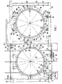
- the double-plate slide 10 shown in FIGS. 1 to 3 has a flat cuboid valve body 11 with a central passage 13 and two flanged on the flat sides and each delimiting the central passage 13 Pipe socket 12, on the inside of each one is not Housing sealing seat shown in detail arranged or formed is. There is one between these housing sealing seats Slide plate 14 slidably mounted, namely within the valve housing 11 transversely to the not shown Fluid line or transverse to the longitudinal axis of the passage 13.
- the slide plate 14 is designed like glasses. It includes a shut-off plate 15 and a pipe bridge 16, wherein in Closed position, the shut-off plate 15 and in the open position Pipe bridge 16 into the fluid line or into the passage 13 is moved into it. The latter position is shown in Fig. 1.
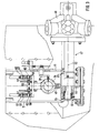
- the pipe bridge 16 has two by a compensator, e.g. B. in the form of a corrugated tube or the like together connected sealing rings 17, which in the open position of the Slider according to Fig. 1 against corresponding sealing seats of the slide housing 11 can be pressed, by spreading elements evenly distributed over the circumference, in particular spring expansion elements 18, which if necessary mechanically, pneumatically or in particular hydraulically compressed can be so that the sealing rings from the Lift off the seal seats of the valve body.
- a compensator e.g. B. in the form of a corrugated tube or the like together connected sealing rings 17, which in the open position of the Slider according to Fig. 1 against corresponding sealing seats of the slide housing 11 can be pressed, by spreading elements evenly distributed over the circumference, in particular spring expansion elements 18, which if necessary mechanically, pneumatically or in particular hydraulically compressed can be so that the sealing rings from the Lift off the seal seats of the valve body.
- spring expansion elements 18 which if necessary mechanically, pneumatically or in particular hydraulically compressed can be
- the shut-off plate 15 consists of two axially spaced apart Shut-off disks 19 which are in the closed position of the Slider also by means of the aforementioned spreading elements 18th can be pressed against the sealing seats of the valve housing 11 mentioned are.
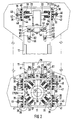
- the sealing rings 17 and shut-off disks 19 are within one Rectangular frame 20 stored.
- This rectangular frame 20 or the slide plate 14 is inside the slide housing 11 roller-bearing, in such a way that the bearing rollers 21, 22nd the slide plate 14 or its frame radially to its direction of movement corresponding to the double arrow 23 in Fig. 1 hold on all sides.
- the slide plate 14 is specific or their frame 20 parallel to the direction of movement 23 two opposite narrow sides, namely in Fig. 1 the lower and upper narrow side with roller bearings.
- On the bottom is the slide plate 14 or the frame 20 by a Pipe profile 24 limited.
- the tube profile 24 On this tube profile 24 are in Slider housing 11 rotatably arranged bearing rollers 21 can be unrolled, the bearing rollers with respect to the longitudinal axis of the profile 28 are arranged in a star shape according to FIG. 2.
- the pipe profile 24 represents in the illustrated embodiment also represents the lower side of the rectangular frame 20 further, the tubular profile 24 is two in the direction of movement 23 the slide plate 14 spaced roller bearing units 25, of which only one is visible in FIG. 1 is shown.
- the roller bearing units 25 each have two sets 26, 27 of star-shaped bearing rollers 21 on.
- Each set of bearing rollers 26 and 27 comprises accordingly Fig. 2 four evenly over the circumference of the tubular profile 24 arranged bearing rollers 21 so that they in two lying perpendicular to each other, where these levels each with the slide plate level 29 Include an angle of approximately 45 °.
- the tubular profile 24 can alternatively to that described Embodiment on the upper narrow side or on one Be flat side of the slide plate attached.
- the slide plate On the upper narrow side, the slide plate is through on the flat side rolling bearing rollers 22 held. They are concrete flat rolling rollers 22 a guide bar in Assigned shape of a rectangular hollow profile 30. The axes of rotation the bearing rollers 22 extend parallel to the slide plate plane 29.
- the upper rectangular hollow section 30 two bearing roller units associated with two pairs of bearing rollers 31, 32, respectively the bearing roller units in the direction of movement 23 also are spaced from each other, namely each in the corner area the valve housing 11 are. Even the tube profile 24 associated roller bearing units 25 are located in each case in the opposite corner area of the valve body 11.
- the bearing rollers are 21 as well as the bearing rollers 22 each individually assigned Longitudinal guide surfaces of the tubular profile 24 and Rectangular hollow profile 30 deliverable, so that manufacturing tolerances can be compensated.
- the bearing rollers 21 are also how the bearing rollers 22 in bearing blocks 33 and 34 rotatably held.
- the bearing blocks 33, 34 are in the illustrated Embodiment over four at the corners of one imaginary square arranged adjusting screws 35 and 36 supported on the associated wall of the slide housing 11.
- the counter of the by means of the adjusting screw 35 and 36th Relative position is set using a between the Adjustment screws, especially centrally between them arranged lock screw 37 or 38.
- the adjusting screws 35 and 36 are screwed through the valve housing wall, until the distal end abuts the associated one Bearing block 33 or 34 comes.
- the screw depth of the Adjusting screws 35, 36 can be used in a conventional manner hold on with lock nuts 39 or 40.
- the adjusting and counter screws are on the outside of the slide housing by a detachably attached hood 41 or 42 covered in a fluid-tight manner, provided that it is fluid-tight trained slide valve 11 is.
- the fluid tight cover is incorporated by on the edge of the cover hood Ring seals 43 and 44, for. B. in the form of O-rings, guaranteed.
- the attachment of the covers 41 or 42 is carried out by fastening screws 45 or 46, which each passed through the hoods and in the valve housing wall is screwed in.
- the slide plate 14 is in the illustrated embodiment by a chain wheel drive 47 in the direction of the double arrow 23 reciprocable.
- the chain wheel drive 47 has one on the lower narrow side in FIGS. 1 and 3 the slide plate 14, specifically on the underside of Pipe profile 24 attached chain 48 and an engaging in this, with a drive, in particular hydraulic motor 49 operatively connected sprocket 50.
- the sprocket 50 is in one on the valve housing 11, namely on its lower narrow side Mounted fluid-tight housing 51, wherein the drive shaft geared to the sprocket 50 52 is led out of the sprocket housing 51 in a fluid-tight manner.
- the valve body 11 has flanges on its lower narrow side the sprocket housing 51 has a passage 53 in the under Interposition of an annular seal 54, in particular in the form an O-ring, the sprocket housing 51 is fitted, then compared to the slide housing 11 by means of adjusting and fastening screws 55 (see Fig. 1) adjusted and fixed will.
- adjusting and fastening screws 55 There are preferably four adjusting and fastening screws provided such that they are in top view of the Sprocket housing 51 form the corners of an imaginary rectangle.
- the sprocket housing is by means of the adjusting and fastening screws 51 and thus also the valve body side sprocket 50 protruding from sprocket housing 51 while maintaining the fluid tightness between the inside of the Slider housing 11 and the area around at the bottom of the tubular profile 24 attached drive chain 48 more or less adjustable, so that a practically backlash-free Engagement between sprocket 50 and drive chain 48 guaranteed is.
- the shut-off plate 15 also consists of two axially adjustable shut-off disks 19 which in the closed position of the slide also by means of the mentioned Spreading elements 18 against the sealing seats mentioned Slider housing 11 are pressed.
- the sealing rings 17 of the Pipe bridge 16 and the shut-off disks 19 of the shut-off plate 15 are according to FIGS. 1 to 3 by radial and axial directional adjusting screws 56 and 57 within the frame 20 of the slide plate 14 held.
- the radially directed Adjusting screws 56 rest on their screw heads 58 Frame 20 of the slide plate 14 on a sliding bearing. To this Way is within the frame 20 of the slide plate 14 axial guidance of the sealing rings 17 and shut-off disks 19 ensured; because as stated above, the sealing rings are 17 of the pipe bridge 16 and the shut-off disks 19 of the shut-off plate 15 axially apart by the expansion elements 18 or movable towards each other.
- the corresponding tour is carried out the aforementioned adjusting screws 56 with the frame 20 Obtain screw heads 58.
- the axially directed adjusting screws 57 are each between the two sealing rings 17 of the pipe bridge 16 or between the two shut-off disks 19 of the shut-off plate 15 are arranged. They form an axial stop for the maximum axial approach of the sealing rings 17 or shut-off disks 19.
- the axially directed Adjustment screws are in between between the metal blocks arranged in both sealing rings or shut-off disks 59 screwed in, in the axial direction on the each diametrically opposite sides.
- the metal blocks 59 are each part of the frame 20 of the slide plate 14 or firmly connected to the slide plate frame 20.
- Each sealing ring 17 and each shut-off disk 19 has radial directed tabs 60 on each other in the axial direction swear. Between the tabs 60 of the associated Sealing rings or mutually associated shut-off discs are the above-mentioned expansion elements 18 are effective. Furthermore are the radially directed adjusting screws on the tabs 60 56 arranged, namely on the rectangular sides of the Frame 20 facing tabs 60. For this purpose are on the corresponding tabs 60 threaded sleeves 61 arranged, welded in particular, in which then the radially directed Adjusting screws 56 can be screwed in. The fixation of the radially directed adjusting screws 56 are carried out in the usual way Way by lock nuts 62.
Landscapes
- Engineering & Computer Science (AREA)
- General Engineering & Computer Science (AREA)
- Mechanical Engineering (AREA)
- Sliding Valves (AREA)
- Details Of Valves (AREA)
- Rolling Contact Bearings (AREA)
Claims (17)
- Robinet-vanne pour grosses conduites de fluides, en particulier robinet-vanne à double opercule, comportant une vanne (14) du type lunette qui est mobile à l'intérieur du corps (11) du robinet perpendiculairement à la conduite de fluide et comprend d'une part un obturateur (15) et d'autre part un pont tubulaire (16), en position fermée, l'obturateur (15), et en position ouverte, le pont tubulaire (16), étant engagé dans la conduite de fluide, caractérisé par le fait que la vanne (14) est appuyée sur des galets à l'intérieur du corps (11) de façon telle que les galets (21, 22) la tiennent radialement par rapport à sa direction de mouvement (23) de tous les côtés.
- Robinet-vanne selon la revendication 1, caractérisé par le fait que la vanne (14) est appuyée sur des galets parallèlement à la direction de mouvement (23) sur deux petits côtés opposés.
- Robinet-vanne selon la revendication 2, caractérisé par le fait que la vanne (14) est limitée sur un petit côté s'étendant parallèlement à la direction de mouvement (23) par un profilé de guidage, en particulier un profilé polygonal, rond plein ou tubulaire (24), sur lequel peuvent rouler des galets (21) montés tournants dans le corps (11) du robinet, ces galets (21) étant disposés à peu près en étoile par rapport à l'axe longitudinal (28) du profilé.
- Robinet-vanne selon la revendication 3, caractérisé par le fait qu'au profilé de guidage (24) sont associés au moins deux ensembles d'appui à galets (25) espacés dans la direction de mouvement (23) de la vanne (14) qui présentent chacun au moins un groupe, en particulier deux groupes (26, 27), de galets (21) disposés en étoile.
- Robinet-vanne selon la revendication 4, caractérisé par le fait que chaque groupe de galets (26, 27) présente au moins trois, en particulier quatre, galets (21) disposés régulièrement sur la circonférence du profilé de guidage, en particulier du profilé tubulaire (24), les galets, dans le second cas, étant situés dans deux plans perpendiculaires qui font chacun un angle d'environ 45° avec le plan (29) de la vanne.
- Robinet-vanne selon l'une des revendications 3 à 5, caractérisé par le fait que la vanne (14) est tenue sur l'autre petit côté parallèle à la direction de mouvement (23) par des galets roulant du côté plat (22).
- Robinet-vanne selon la revendication 6, caractérisé par le fait qu'aux galets roulant du côté plat (22) est associée une nervure de guidage, en particulier formée d'un profilé creux rectangulaire (30), sur laquelle les galets (22) peuvent rouler.
- Robinet-vanne selon la revendication 7, caractérisé par le fait qu'à la nervure de guidage, en particulier formée d'un profilé creux rectangulaire (30), sont associés au moins deux ensembles de galets (63) espacés dans la direction de mouvement (23) de la vanne (14) et comprenant au moins une, en particulier deux, paires de galets (31, 32).
- Robinet-vanne selon l'une des revendications 3 à 8, caractérisé par le fait que les galets (21; 22) peuvent être approchés individuellement des surfaces de guidage longitudinales associées du profilé de guidage (24) et de la nervure de guidage (30).
- Robinet-vanne selon la revendication 9, caractérisé par le fait qu'à chaque support de galet (33 ; 34) sont associées au moins une vis de réglage, en particulier au moins deux vis de réglage (35 ; 36) espacées et appuyées sur le corps (11) du robinet et une contre-vis (37 ; 38) placée entre les précédentes et appuyée sur le support (33 ; 34).
- Robinet-vanne selon la revendication 10, caractérisé par le fait que les vis de réglage (35 ; 36) et les contre-vis (37 ; 38) sont couvertes sur le côté extérieur du corps du robinet, de manière étanche aux fluides (joints annulaires 43 ; 44), par un capuchon fixé de manière amovible (41 ; 42) ou un élément semblable.
- Robinet-vanne selon l'une des revendications 1 à 11, dans lequel un dispositif moteur à crémaillère ou à roue à chaíne (47) peut faire aller et venir la vanne (14), le dispositif moteur à roue à chaíne (47) présentant une chaíne (48) fixée à un petit côté de la vanne (14) s'étendant parallèlement à la direction de mouvement (23) et une roue (50) s'engageant dans cette chaíne et entraínée par un organe moteur (49), caractérisé par le fait que la roue à chaíne (50) est montée dans une boíte (51) pouvant être bridée de manière étanche aux fluides au corps (11) du robinet, l'arbre moteur (52) qui entraíne la roue à chaíne (50) sortant de manière étanche aux fluides de la boíte à roue à chaíne (51).
- Robinet-vanne selon la revendication 12, caractérisé par le fait que la boíte à roue à chaíne (51) et avec elle la roue à chaíne (50) qui en fait saillie du côté du corps du robinet peuvent être approchées de la chaíne motrice (48), fixée à la vanne (14), au moyen de vis de réglage et de fixation (55) avec maintien de l'étanchéité aux fluides entre l'intérieur du corps (11) du robinet et le milieu environnant.
- Robinet-vanne selon la revendication 13, caractérisé par le fait que son corps (11) présente pour le bridage de la boíte à roue à chaíne (51) un passage (53) dans lequel on peut faire entrer celle-ci avec intercalation d'un joint annulaire (54), en particulier d'un joint torique, pour pouvoir ensuite l'ajuster par rapport au corps (11) et la fixer à celui-ci au moyen des vis de réglage et de fixation (55).
- Robinet-vanne selon l'une des revendications 1 à 14, dans lequel le pont tubulaire (16) présente deux joints annulaires (17) reliés par un compensateur qui peuvent, lorsque le robinet est ouvert, être serrés contre des sièges correspondants du corps (11) au moyen d'un dispositif d'écartement (18), et l'obturateur (15) comprend deux disques (19) qui peuvent, lorsque le robinet est fermé, être serrés également au moyen d'un dispositif d'écartement (18) contre les sièges précités du corps (11), caractérisé par le fait que les joints annulaires (17) du pont tubulaire (16) et/ou les disques (19) de l'obturateur (15) sont tenus à l'intérieur d'un cadre (20) de la vanne (14) par des vis de réglage dirigées radialement (56) et des vis de réglage dirigées axialement (57).
- Robinet-vanne selon la revendication 15, caractérisé par le fait que les vis de réglage dirigées à peu près radialement (56) sont en appui glissant par leur tête (58) sur le cadre (20) de la vanne (14).
- Robinet-vanne selon l'une des revendications 15 et 16, caractérisé par le fait que les vis de réglage dirigées axialement (57) sont placées entre les deux joints annulaires (17) du pont tubulaire (16) et/ou les deux disques (19) de l'obturateur (15) et forment une butée pour le rapprochement axial maximal des joints annulaires (17) ou des disques (19).
Applications Claiming Priority (3)
| Application Number | Priority Date | Filing Date | Title |
|---|---|---|---|
| DE4405836 | 1994-02-23 | ||
| DE4405836A DE4405836A1 (de) | 1994-02-23 | 1994-02-23 | Schieber zum Absperren großer Fluidleitungen, insbesondere Doppelplattenschieber |
| PCT/EP1995/000185 WO1995023306A1 (fr) | 1994-02-23 | 1995-01-19 | Robinet-vanne monte sur rouleaux, notamment robinet-vanne a double opercule |
Publications (2)
| Publication Number | Publication Date |
|---|---|
| EP0697081A1 EP0697081A1 (fr) | 1996-02-21 |
| EP0697081B1 true EP0697081B1 (fr) | 1998-07-22 |
Family
ID=6511003
Family Applications (1)
| Application Number | Title | Priority Date | Filing Date |
|---|---|---|---|
| EP95906974A Expired - Lifetime EP0697081B1 (fr) | 1994-02-23 | 1995-01-19 | Robinet-vanne monte sur rouleaux, notamment robinet-vanne a double opercule |
Country Status (11)
| Country | Link |
|---|---|
| US (1) | US5667196A (fr) |
| EP (1) | EP0697081B1 (fr) |
| JP (1) | JP2777288B2 (fr) |
| KR (1) | KR100193545B1 (fr) |
| CN (1) | CN1045815C (fr) |
| AT (1) | ATE168750T1 (fr) |
| DE (2) | DE4405836A1 (fr) |
| ES (1) | ES2122539T3 (fr) |
| RU (1) | RU2123629C1 (fr) |
| UA (1) | UA41924C2 (fr) |
| WO (1) | WO1995023306A1 (fr) |
Families Citing this family (9)
| Publication number | Priority date | Publication date | Assignee | Title |
|---|---|---|---|---|
| DE29713428U1 (de) * | 1997-07-28 | 1997-11-20 | Zimmermann & Jansen GmbH, 52355 Düren | Leitrohrschieber zum Öffnen und Absperren großer Fluidleitungen |
| DE29820000U1 (de) | 1998-11-09 | 1999-02-18 | Zimmermann & Jansen GmbH, 52355 Düren | Vorrichtung zum Absperren großer Fluidleitungen |
| DE10343298A1 (de) * | 2003-09-18 | 2005-04-14 | Z & J Technologies Gmbh | Verkokungstrommel |
| KR100599817B1 (ko) * | 2004-08-24 | 2006-07-14 | 주식회사 무진기연 | 핵연료 이송관용 블라인드 플랜지 |
| KR200384604Y1 (ko) * | 2005-02-01 | 2005-05-17 | 김태조 | 안경형 배관파이프 개폐 분리구 |
| ES2405933B1 (es) * | 2011-11-29 | 2014-04-07 | Carlos GARCÍA LÓPEZ | Válvula compuerta con tablero con ruedas. |
| CN103225699B (zh) * | 2013-03-29 | 2015-09-09 | 成都瑞柯林工程技术有限公司 | 眼镜阀及其阀板导向驱动机构 |
| CN103267140B (zh) * | 2013-06-03 | 2015-06-10 | 石家庄阀门一厂股份有限公司 | 一种高压封闭式眼镜阀的承压系统 |
| DE102015104555A1 (de) * | 2015-03-26 | 2016-09-29 | Z & J Technologies Gmbh | Doppelplattenschieber, Absperrplatte und Verfahren zum Abdichten eines Doppelplattenschiebers |
Family Cites Families (11)
| Publication number | Priority date | Publication date | Assignee | Title |
|---|---|---|---|---|
| DE529439C (de) * | 1928-12-08 | 1931-11-03 | Hellmut Geiger Dipl Ing | Mit seitlichen Rollen in Fuehrungen eines einteiligen Gehaeuses laufender Absperrschieber |
| CH492151A (de) * | 1968-04-25 | 1970-06-15 | Ingenieurbureau Hausammann & I | Schieberventil für Gase, Flüssigkeiten und Gas-Feststoff-Gemische |
| US3527440A (en) * | 1968-06-17 | 1970-09-08 | Tower Iron Works Inc | Blanking plate for gas flow passages |
| US3768773A (en) * | 1971-12-30 | 1973-10-30 | Palmer Fluid Controls Inc | Sluice gate |
| US3907250A (en) * | 1973-08-02 | 1975-09-23 | John J Kane | Sluice gate |
| DE2342448A1 (de) * | 1973-08-22 | 1975-03-20 | Scitech Corp | Schieberventil mit rollenlagerung |
| US4235256A (en) * | 1979-05-07 | 1980-11-25 | Cominco Ltd. | Damper assembly for gas duct |
| US4482296A (en) * | 1981-11-16 | 1984-11-13 | Terry Corporation | Bladed rotor assembly and method of forming same |
| US4582296A (en) * | 1985-03-04 | 1986-04-15 | Lothar Bachmann | Composite blade for dampers for ducts of large cross sectional areas |
| DE3609635A1 (de) * | 1986-03-21 | 1987-09-24 | Westark Armaturen | Flachschieber mit einer profilschiene zur aufnahme einer profildichtung |
| DE8706251U1 (de) * | 1987-04-30 | 1987-09-17 | Westark-Gmbh Armaturenfabrik, 4620 Castrop-Rauxel | Geschweißtes Stahlgehäuse für eine Großarmatur, insbesondere einen Absperrschieber und/oder eine Rückschlagklappe |
-
1994
- 1994-02-23 DE DE4405836A patent/DE4405836A1/de not_active Withdrawn
-
1995
- 1995-01-19 KR KR1019950704570A patent/KR100193545B1/ko not_active Expired - Fee Related
- 1995-01-19 EP EP95906974A patent/EP0697081B1/fr not_active Expired - Lifetime
- 1995-01-19 DE DE59502874T patent/DE59502874D1/de not_active Expired - Lifetime
- 1995-01-19 WO PCT/EP1995/000185 patent/WO1995023306A1/fr not_active Ceased
- 1995-01-19 ES ES95906974T patent/ES2122539T3/es not_active Expired - Lifetime
- 1995-01-19 US US08/535,148 patent/US5667196A/en not_active Expired - Fee Related
- 1995-01-19 CN CN95190110A patent/CN1045815C/zh not_active Expired - Fee Related
- 1995-01-19 RU RU95118181/06A patent/RU2123629C1/ru not_active IP Right Cessation
- 1995-01-19 AT AT95906974T patent/ATE168750T1/de active
- 1995-01-19 UA UA95104567A patent/UA41924C2/uk unknown
- 1995-01-19 JP JP7522089A patent/JP2777288B2/ja not_active Expired - Fee Related
Also Published As
| Publication number | Publication date |
|---|---|
| US5667196A (en) | 1997-09-16 |
| ES2122539T3 (es) | 1998-12-16 |
| CN1045815C (zh) | 1999-10-20 |
| ATE168750T1 (de) | 1998-08-15 |
| EP0697081A1 (fr) | 1996-02-21 |
| WO1995023306A1 (fr) | 1995-08-31 |
| DE59502874D1 (de) | 1998-08-27 |
| JPH09501483A (ja) | 1997-02-10 |
| UA41924C2 (uk) | 2001-10-15 |
| DE4405836A1 (de) | 1995-08-24 |
| KR100193545B1 (ko) | 1999-06-15 |
| CN1123566A (zh) | 1996-05-29 |
| RU2123629C1 (ru) | 1998-12-20 |
| KR960702085A (ko) | 1996-03-28 |
| JP2777288B2 (ja) | 1998-07-16 |
Similar Documents
| Publication | Publication Date | Title |
|---|---|---|
| EP0450646B1 (fr) | Vanne à tiroir composé de deux plaques | |
| DE29623103U1 (de) | Schieber, insbesondere Rohrbrückenschieber | |
| EP0697081B1 (fr) | Robinet-vanne monte sur rouleaux, notamment robinet-vanne a double opercule | |
| DE3133273A1 (de) | "reinigbares doppelsitzventil mit leckkontrolle" | |
| DE2528546C2 (de) | Abdichtung für eine nichtsteigende Spindel eines Schiebers | |
| DE3525685A1 (de) | Absperrorgan | |
| DE2821635A1 (de) | Hubvorrichtung | |
| DE1946581B1 (de) | Absperrschieber | |
| DE3043279A1 (de) | Messblenden-vorrichtung | |
| AT413237B (de) | Absperrschieber für druckrohrleitungen | |
| DE2913942A1 (de) | Absperrschieber | |
| DE102009054062A1 (de) | Einrichtung zum Verschwenken eines Segmenttores | |
| DE3139081C2 (de) | Verbindungsstück zum Anflanschen von normierten Behältnissen an die an der Decke gelegene Beschickungsöffnung einer Heißen Zelle | |
| EP1793150B1 (fr) | Dispositif d'arrêt, notamment pour conduites sous pression | |
| DE4110186C2 (fr) | ||
| DE2457960A1 (de) | Druckentlasteter schieber | |
| EP0612386B1 (fr) | Vanne d'arret | |
| DE2739750B1 (de) | Schieberverschluss fuer eine Giesspfanne | |
| DE4447309A1 (de) | Regelventil | |
| EP0379233A1 (fr) | Dispositif de fermeture | |
| DE7809423U1 (de) | Rohrleitungsschieber | |
| DE2843017A1 (de) | Absperr- und durchlassventil mit einer sperreinrichtung zur sequentiellen steuerung der ventilelemente | |
| DE202022101117U1 (de) | Präzisions-Durchflussbegrenzungsventil | |
| DE20101545U1 (de) | Vorrichtung zum Antrieb eines eine Hubbewegung und eine Schwenkbewegung ausführenden Organs | |
| DE2728929A1 (de) | Durchgang durch eine wand zwischen zwei benachbarten becken |
Legal Events
| Date | Code | Title | Description |
|---|---|---|---|
| PUAI | Public reference made under article 153(3) epc to a published international application that has entered the european phase |
Free format text: ORIGINAL CODE: 0009012 |
|
| AK | Designated contracting states |
Kind code of ref document: A1 Designated state(s): AT BE DE ES FR IT LU NL SE |
|
| 17P | Request for examination filed |
Effective date: 19960111 |
|
| GRAG | Despatch of communication of intention to grant |
Free format text: ORIGINAL CODE: EPIDOS AGRA |
|
| 17Q | First examination report despatched |
Effective date: 19970919 |
|
| GRAG | Despatch of communication of intention to grant |
Free format text: ORIGINAL CODE: EPIDOS AGRA |
|
| GRAH | Despatch of communication of intention to grant a patent |
Free format text: ORIGINAL CODE: EPIDOS IGRA |
|
| GRAH | Despatch of communication of intention to grant a patent |
Free format text: ORIGINAL CODE: EPIDOS IGRA |
|
| GRAA | (expected) grant |
Free format text: ORIGINAL CODE: 0009210 |
|
| AK | Designated contracting states |
Kind code of ref document: B1 Designated state(s): AT BE DE ES FR IT LU NL SE |
|
| REF | Corresponds to: |
Ref document number: 168750 Country of ref document: AT Date of ref document: 19980815 Kind code of ref document: T |
|
| REF | Corresponds to: |
Ref document number: 59502874 Country of ref document: DE Date of ref document: 19980827 |
|
| ET | Fr: translation filed | ||
| REG | Reference to a national code |
Ref country code: ES Ref legal event code: FG2A Ref document number: 2122539 Country of ref document: ES Kind code of ref document: T3 |
|
| PLBE | No opposition filed within time limit |
Free format text: ORIGINAL CODE: 0009261 |
|
| STAA | Information on the status of an ep patent application or granted ep patent |
Free format text: STATUS: NO OPPOSITION FILED WITHIN TIME LIMIT |
|
| 26N | No opposition filed | ||
| PGFP | Annual fee paid to national office [announced via postgrant information from national office to epo] |
Ref country code: LU Payment date: 20030127 Year of fee payment: 9 |
|
| PG25 | Lapsed in a contracting state [announced via postgrant information from national office to epo] |
Ref country code: LU Free format text: LAPSE BECAUSE OF NON-PAYMENT OF DUE FEES Effective date: 20040119 |
|
| PGFP | Annual fee paid to national office [announced via postgrant information from national office to epo] |
Ref country code: ES Payment date: 20080124 Year of fee payment: 14 |
|
| PGFP | Annual fee paid to national office [announced via postgrant information from national office to epo] |
Ref country code: SE Payment date: 20080104 Year of fee payment: 14 Ref country code: NL Payment date: 20080118 Year of fee payment: 14 Ref country code: IT Payment date: 20080119 Year of fee payment: 14 |
|
| PGFP | Annual fee paid to national office [announced via postgrant information from national office to epo] |
Ref country code: FR Payment date: 20080131 Year of fee payment: 14 |
|
| PGFP | Annual fee paid to national office [announced via postgrant information from national office to epo] |
Ref country code: BE Payment date: 20080130 Year of fee payment: 14 |
|
| EUG | Se: european patent has lapsed | ||
| NLV4 | Nl: lapsed or anulled due to non-payment of the annual fee |
Effective date: 20090801 |
|
| REG | Reference to a national code |
Ref country code: FR Ref legal event code: ST Effective date: 20091030 |
|
| PG25 | Lapsed in a contracting state [announced via postgrant information from national office to epo] |
Ref country code: NL Free format text: LAPSE BECAUSE OF NON-PAYMENT OF DUE FEES Effective date: 20090801 |
|
| PG25 | Lapsed in a contracting state [announced via postgrant information from national office to epo] |
Ref country code: BE Free format text: LAPSE BECAUSE OF NON-PAYMENT OF DUE FEES Effective date: 20090131 |
|
| REG | Reference to a national code |
Ref country code: ES Ref legal event code: FD2A Effective date: 20090120 |
|
| PG25 | Lapsed in a contracting state [announced via postgrant information from national office to epo] |
Ref country code: FR Free format text: LAPSE BECAUSE OF NON-PAYMENT OF DUE FEES Effective date: 20090202 Ref country code: ES Free format text: LAPSE BECAUSE OF NON-PAYMENT OF DUE FEES Effective date: 20090120 |
|
| PG25 | Lapsed in a contracting state [announced via postgrant information from national office to epo] |
Ref country code: IT Free format text: LAPSE BECAUSE OF NON-PAYMENT OF DUE FEES Effective date: 20090119 |
|
| PG25 | Lapsed in a contracting state [announced via postgrant information from national office to epo] |
Ref country code: SE Free format text: LAPSE BECAUSE OF NON-PAYMENT OF DUE FEES Effective date: 20090120 |
|
| PGFP | Annual fee paid to national office [announced via postgrant information from national office to epo] |
Ref country code: AT Payment date: 20110127 Year of fee payment: 17 |
|
| PGFP | Annual fee paid to national office [announced via postgrant information from national office to epo] |
Ref country code: DE Payment date: 20110329 Year of fee payment: 17 |
|
| REG | Reference to a national code |
Ref country code: AT Ref legal event code: MM01 Ref document number: 168750 Country of ref document: AT Kind code of ref document: T Effective date: 20120119 |
|
| PG25 | Lapsed in a contracting state [announced via postgrant information from national office to epo] |
Ref country code: DE Free format text: LAPSE BECAUSE OF NON-PAYMENT OF DUE FEES Effective date: 20120801 |
|
| REG | Reference to a national code |
Ref country code: DE Ref legal event code: R119 Ref document number: 59502874 Country of ref document: DE Effective date: 20120801 |
|
| PG25 | Lapsed in a contracting state [announced via postgrant information from national office to epo] |
Ref country code: AT Free format text: LAPSE BECAUSE OF NON-PAYMENT OF DUE FEES Effective date: 20120119 |