EP0697165B1 - Microwave ovens - Google Patents
Microwave ovens Download PDFInfo
- Publication number
- EP0697165B1 EP0697165B1 EP94914465A EP94914465A EP0697165B1 EP 0697165 B1 EP0697165 B1 EP 0697165B1 EP 94914465 A EP94914465 A EP 94914465A EP 94914465 A EP94914465 A EP 94914465A EP 0697165 B1 EP0697165 B1 EP 0697165B1
- Authority
- EP
- European Patent Office
- Prior art keywords
- oven
- band
- microwave
- stage
- waveguide
- Prior art date
- Legal status (The legal status is an assumption and is not a legal conclusion. Google has not performed a legal analysis and makes no representation as to the accuracy of the status listed.)
- Expired - Lifetime
Links
Images



Classifications
-
- H—ELECTRICITY
- H05—ELECTRIC TECHNIQUES NOT OTHERWISE PROVIDED FOR
- H05B—ELECTRIC HEATING; ELECTRIC LIGHT SOURCES NOT OTHERWISE PROVIDED FOR; CIRCUIT ARRANGEMENTS FOR ELECTRIC LIGHT SOURCES, IN GENERAL
- H05B6/00—Heating by electric, magnetic or electromagnetic fields
- H05B6/64—Heating using microwaves
- H05B6/78—Arrangements for continuous movement of material
- H05B6/782—Arrangements for continuous movement of material wherein the material moved is food
-
- H—ELECTRICITY
- H05—ELECTRIC TECHNIQUES NOT OTHERWISE PROVIDED FOR
- H05B—ELECTRIC HEATING; ELECTRIC LIGHT SOURCES NOT OTHERWISE PROVIDED FOR; CIRCUIT ARRANGEMENTS FOR ELECTRIC LIGHT SOURCES, IN GENERAL
- H05B6/00—Heating by electric, magnetic or electromagnetic fields
- H05B6/64—Heating using microwaves
- H05B6/70—Feed lines
- H05B6/707—Feed lines using waveguides
- H05B6/708—Feed lines using waveguides in particular slotted waveguides
Definitions
- This invention relates to microwave ovens particularly, but not exclusively, to industrial ovens for food products such as biscuits, snacks, chips, meat substitutes.
- the invention may however be applied to non-food products, such as to the heating of plastics.
- Continuous ovens for food products such as biscuits can be designed to have a plurality of zones through which each food product travels in sequence. Such zones can be used to provide different heating and baking conditions.
- Multi-media ovens combine different means of heating a food product in the different zones, such as cyclotherm radiant heating, gas or electrically heated convection, near infrared radiant heat, and are well-known in the industry.
- Such an oven which employs microwave heating in addition to another form of heating is hereinafter referred to as a 'combined oven'.
- Microwave heating provides means to induce a rapid transfer of energy to the product, the level of energy transfer being selected to provide a desired effect within the product.
- the first microwave zone induces a rapid rise in temperature within the product
- the second microwave zone enhances development
- the third and fourth microwave zones reduce the moisture content of the product prior to leaving the oven.
- Conventionally heated industrial ovens for food products generally use a metal band to support and convey the food products through the oven.
- the band may be a metal strip or a mesh band.
- Industrial microwave units basically consist of a microwave generator and a microwave applicator.
- 'band-parallel' and 'band-normal' used herein are intended to refer to directions which are parallel to and normal to, respectively, the plane of the oven band. Whilst the oven band will often be horizontal, it should be appreciated that the oven band need not always be horizontal since products can be conveyed on a sloping band.
- a microwave tunnel oven comprising a microwave applicator extending transversely of an electrically conductive oven band and intended to produce electric fields in the region above the band and adjacent thereto, with a plane of polarisation substantially perpendicular to said conductive oven band, and propagated in a direction substantially lengthwise of the band.
- the band-parallel component (E h ) of the electric field is constrained by the conductive band to be small in the region closely adjacent to the band.
- the vertical component (E v ) of the electric field in the region occupied by the product is arranged to be sufficient to provide heating of the product carried on the conductive band.
- the applicators in accordance with the present invention are essentially configured to create, in the absence of a product, radiation propagated lengthwise of the band in the (TEM) transverse electromagnetic mode, or TM 1 mode. The presence of a product will distort the radiation pattern.
- Designs in accordance with the invention aimed at producing such an E-field take account of the conductive oven band in the overall design of the microwave applicator. If the head-space between the product and the applicator is small (such as 40 mm), the equivalent of a parallel-plate transmission line can be created, supporting the TEM mode. If the head space is greater than 60 mm, a higher order mode can be supported.
- Such an applicator configuration can provide improved heating uniformity across the oven width.
- Means for broadcasting such a waveform will be described hereinafter, and relate to a microwave generator frequency of 2450 MHz. Other (lower) frequencies can be used but, due to the resultant longer wavelength, less uniform illumination will be achieved.
- the microwave applicator preferably comprises an elongate feeder waveguide extending substantially transversely of the band and positioned above the band, the waveguide being provided with a plurality of longitudinally spaced-apart radiation emitter means adapted to emit radiation with a substantially vertically polarised electrical component in the near vicinity of the band, and preferably substantially throughout the vertical thickness of the product.
- a phased array of said emitter means is preferably employed to broadcast the waveform, that is there is a uniform phase difference between adjacent pairs of emitter means of the plurality of emitter means.
- the feeder waveguide is preferably a rectangular section waveguide.
- the emitter means may be slots in one wall of the waveguide or antenna associated with respective probes which extend inwardly of the waveguide from a wall of the waveguide.
- the emitter means are preferably spaced-apart along the waveguide on a pitch of substantially half a guide wavelength.
- the antennas may be carried on the underside of the waveguide.
- the antennas could be connected to respective probes located in the waveguide by respective waveguide links, such as coaxial waveguide links.
- each slot is preferably of a length substantially half a free-space wavelength.
- Such slots are preferably provided in a broad side of the waveguide which is oriented substantially normal to the band.
- US-A-4570045 shows an oven comprising an endless band of metal caused to pass through an oven chamber, whereby coal carried by the band is subjected to microwaves existing within the treatment space, the microwaves being emitted from slots beneath aligned slots in waveguides extending transversely of the oven band.
- a microwave tunnel oven for subjecting products conveyed through the oven to microwave radiation
- a tunnel oven casing the oven casing comprising spaced apart tunnel oven side-walls and an oven roof connecting the side-walls, an electrically conductive product- supporting conveyor band positioned between the side-walls and beneath the roof to extend lengthwise of the tunnel, band drive means operative to drive the band, a microwave generator means, a microwave applicator, positioned between the side-walls and above the band, microwave supply means connecting the generator means to the applicator, the applicator comprising an elongate microwave emitter assembly extending transversely of the oven band, the emitter assembly comprising a plurality of spaced-apart microwave emitter means characterised by the provision of microwave launch means extending longitudinally of the oven and above the band from adjacent to the emitter assembly, the emitter assembly being operable to emit radiation into the oven generally in a longitudinal direction of the oven with a plane of polarisation substantially perpendicular to the oven band, at least a portion
- the emitter assembly may comprise a feeder waveguide extending transversely of the oven band, and a plurality of spaced-apart slots in the feeder waveguide, the slots facing longitudinally of the oven for emitting radiation into the oven generally in a longitudinal direction of the oven with a plane of polarisation substantially perpendicular to the oven band at least a portion of the launch means and the band defining therebetween a microwave treatment through which the products are conveyed in use for being subjected to microwave radiation, the launch means being configured to maintain the polarisation of the radiation in the treatment space substantially perpendicular to the oven band, and the microwave launch means may comprise, as viewed in longitudinal vertical section of the oven, a first stage positioned adjacent to the feeder waveguide and a second stage remote from the feeder waveguide, the first stage comprising upper and lower first stage plates disposed above and below respectively the slots and extending generally longitudinally of the oven from the feeder waveguide, the second stage comprising a panel extending closer to the band in proceeding away from the first stage, the upper first stage plate meeting the second
- said upper and lower first stage plates are substantially flat plates, said upper first stage plate extending upwardly and longitudinally, with respect to the band, from said feeder waveguide, said lower first stage plate extending downwardly and longitudinally, with respect to the band, from said feeder waveguide, so as to define a cavity in the near field of the slots which expands in the direction proceeding away from said slots.
- a parallel plate portion of the applicator may be provided, said parallel plate portion extending substantially parallel to the band and away from the launch section of the applicator, with which the parallel plate portion is continuous.
- Such a parallel plate portion effectively extends the length of the applicator in the longitudinal direction of the band, to retain the polarisation of the waveform when the products to be heated are low loss products which do not readily absorb the waveform and accordingly allow the waveform to travel further along the oven.
- the launch means may be configured to maintain the polarisation of the radiation in the treatment space substantially perpendicular to the oven band characterised in that the arrangement is such that the mode of radiation in the treatment space is at least predominantly the TM 1 mode.
- the said plurality of microwave emitter means may comprise a plurality of antennas depending downwardly from said feeder waveguide, and a plurality of probes located in said waveguide, each said probe being directly connected to a respective one of the antennas.
- the plurality of microwave emitter means may be arranged as a phased array, such that there is a uniform phase difference between adjacent pairs of emitter means of said plurality of emitter means, and that the feeder waveguide is located externally of the oven casing, and the plurality of microwave emitter means is connected with the feeder waveguide by a plurality of coaxial waveguide links, the links extending through the oven casing.
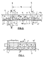
- an oven comprises side-walls S and a roof R.
- the side walls S are spaced-apart by a distance of typically 1 or 1.2 metres.
- Food products 1 are conveyed on a horizontal steel oven band 2 extending between side walls S through a vertically polarised E-field shown E v and E h , broadcast from an array of slots 8 formed on oppositely facing broad sides 3' of a pair of oblong-rectangular cross-section feeder waveguides 3 of a double applicator.
- Launch sections 5 of the applicator consist of first launch stage 6, adjacent to the respective waveguide 3, and a second launch stage remote from the respective feeder waveguide 3 in the form of a panel 7, curved at a radius R 1 to connect the end of the first launch stage smoothly with horizontal plates 11 of the applicator.
- a respective treatment space 7' is defined between the panel 7 and the band 2.
- each launch section 5 is defined by an upper first stage plate 6' and a respective lower first stage plate 6".
- the upper first stage plate 6' in proceeding from the associated waveguide 3 is directed upwardly and longitudinally of the oven, at an angle of 0 to the plane of band 2, whereas the respective lower first stage plate 6" lies beneath the upper first stage plate 6' and extends downwardly in proceeding longitudinally of the oven from the waveguide 3, from below the slots 8, at the same angle 0 relative to the plane of the band 2.
- the upper and lower first stage plate pairs define between them a respective cavity 15, in the near field of the slots 8, which expands in the direction proceeding away from the slots of the respective feeder waveguide 3.
- the longer second stage panel 7 extends closer to the band 2 in proceeding longitudinally of the oven from the connection between the second stage panel 7 and the extremity of the respective upper first stage plate 6' to merge with the horizontal plates 11 of the applicator.
- the applicator as shown in Figure 2, extends for almost the full width of the oven, and the cross-sectional configuration shown in Figure 1 is uniform for that full length of the applicator.
- the feeder waveguides extend through one wall S of the oven for connection to a remote microwave generator means.
- slots 8 of length d 1 are formed in one broad side 3' of each waveguide 3 pitched evenly by dimension d 2 and arranged evenly and alternately about the centre-line 4 of the side 3' at a distance d 3 . This may require a flare to compensate for a bias of power transmitted from the first to the last slot. (Microwave theory would imply that the spacing about the centre-line of each slot should be different as the effect of neighbouring slots varies from slot to slot, depending upon their relative positions.
- the positions of the edges 9 of the first stage plates 6', 6" of the launch section 5 are arranged so that the centre-line of the slots is equidistant between the edges 9 and the centre-line 4 of the broad face 3' of the respective waveguide.
- a base plate 13 extends from the lower edges of lower panels 6", and also defines the lower short side of the feeder waveguides 3, the base plate 13 extending parallel to the band 2 to define between the plate 13 and band 2 a further treatment space 14. Standing waves created in space 14 by reflections from the launch sections 7 provide additional heating of the products 1 as they pass beneath plate 13.
- the upper and lower first stage plates 6' and 6" are set at equal angles 0 relative to the plane of the band 2.
- the plates 6' and 6" could be of different shape and orientation but best results are likely to be achieved when the plates 6' and 6" are arranged in mirror image configuration relative to that plane which includes the centre-line of the slots 8 and is parallel to the plane of the band 2.
- food products 1 are conveyed on a steel oven band 2 beneath an applicator which creates a vertically polarised E-field, shown E v and E h , broadcast from an array of probe-fed monopole antennas 10 located on the bottom face of two rectangular cross-section spaced-apart feeder waveguides 3. Each antenna 10 is fed by a respective probe 10'.
- the launch sections 5 in this case each consist of a flared panel structure 7 set at a radius R 2 to extend between the waveguide 3 and portions 11 of the applicator parallel to the band 2. Dimension d 7 is determined by the power requirements.
- the applicator uses a pair of waveguides 3 extending substantially transverse to the direction of travel of the steel band conveyor 2, each of the waveguide feeds being of oblong-rectangular cross-section, as shown in Figure 1, with the longer dimension of this cross-section disposed vertically and with the slots 8 formed on one of the broad sides 3'.
- This arrangement is used in combination with the launch section 5 to direct the waveform 'through' the top plate of the equivalent parallel plate waveguide.
- the length of the slots 8 is substantially one half the free-space wavelength for the chosen frequency and the slots 8 are spaced apart by one half guide-wavelength.
- Adjacent slots 8 are arranged alternately on opposite sides of the centre-line 4 of the broad face 3' of the waveguide 3 to allow for phase reversal of the waveform in the guide. In this way a substantially uniform microwave illumination can be achieved.
- a second similar pattern of slots 8 to be repeated on the outwardly-facing broad face 3' of the second waveguide 3, but out-of-phase, in the transverse direction of the band, to the first set of slots by an amount equal to one quarter guide-wavelength, compensation for any non-uniformity of microwave illumination can be achieved, in that the accumulated exposure of a single product to the waveform will be evened out when the product has passed through the two fields generated by the respective waveguides 3.
- the launch section 5 of the applicator of Figures 1 and 2 is arranged initially to ensure symmetry in the very near field of the slots 8 and then to provide a guide for the waves 'through' the top plate of the equivalent parallel plate waveguide.
- the exact dimensions are determined empirically to achieve a substantially uniform microwave illumination across the oven band and to maintain vertical polarisation of the E-field.
- the applicator uses an array of probe-fed monopole antennas distributed across the width of the oven but located on the underside of the transverse feeder waveguide.
- each of the monopoles 10 is preferably substantially one quarter the wavelength of the free-space waveform for the chosen frequency.
- Folded monopoles are preferred because they are self-supporting and do not require a ceramic holder.
- the power broadcast from each antenna 10 is proportional to the protrusion of the associated probe 10' into the waveguide, this being arranged to suit the power transmission requirements.
- the configuration of the launch sections 5 in Figure 3 is based on similar principles to those used for the slotted waveguide of Figures 1, 2 but in this case the provision of plates such as plates 6', 6' used in Figures 1, 2 to ensure symmetry in the near field is unnecessary.
- the curved plate 7 extends directly from the respective feeder waveguide 3.
- the arrangement of probes 10 is repeated on a second waveguide 3 but so as to be out-of-phase with respect to the antennas on the first waveguide 3, in the transverse direction of the band, by an amount equal to one quarter the guide wavelength; in a like manner this compensates overall for any non-uniformity of microwave illumination.
- the exact dimensions of the launch sections 5 are determined empirically to achieve a substantially uniform microwave illumination across the oven band and to maintain vertical polarisation of the E-field, but approximate values can be related to the wavelengths used.
- Figure 5 shows that the feeder waveguide 3 fitted with probes 10' may be positioned external to the oven, the probes 10' being connected to respective antennas 10 positioned within the oven by respective coaxial waveguide links 15.
- the central portion of the applicator comprising the pair of waveguides 3 with slots in their broad sides 3', respective upper and lower plates 6' and 6", and base plate 13, is essentially the same as the central portion of the applicator of Figure 1, but the upper plates 6' connect with respective horizontal main applicator plates 20 which extend parallel to the metal band 2 at a spacing d 11 which is greater than 60 mm, typically 70 mm, in order to establish the TM 1 mode in the respective treatment spaces 21 defined between the band 2 and the main applicator plates 20.
- Figure 8 shows schematically the distribution of the electric field in the equivalent parallel plate transmission line supporting the TM 1 mode.
- the electric field is, in fact, parallel to the band, but in proceeding away from the band the electric field rapidly becomes normal to the band, so that effectively the field in the product is perpendicular to the band.
- the electric field lines again become horizontal. Therefore the products would preferably be chosen to have a maximum height less than half d 11 , and this represents the effective treatment space in this case.
- the TM 1 mode may alternatively be designated the TM 01 mode, since there are no loops of the electric field in the direction extending parallel to but transversely of the metal band 2.
- the ends of the main plates 20 remote from the waveguides 3 are continuous with downwardly and outwardly sloping flat plates 7, extending at an angle of typically 45° to the band, the plates 7 connecting with horizontal plates 11 spaced at a distance d 10 above the band 2.
- the distance d 10 is typically 15 to 20 mm in order to support the TEM mode in the further treatment spaces 11'.
- the length of d 12 of the main plates 20 in Figures 6 is typically 2
- Figure 7 shows an equivalent arrangement to that of Figure 6 but employing antennas 10 in a similar manner to Figure 3.
- the dimensions d 10 , d 11 and d 12 are typically as given for Figure 6.
- the TM 1 mode is supported in the main treatment spaces 21, whereas the TEM mode is supported in the further treatment spaces 11'.
- a microwave circuit 22 is defined to enclose the emitter assembly, launch section and oven band.
- the oven band 2 is supported by electrically conductive skids 23, running lengthwise of the band 2, on the base 25 of the microwave containment circuit 22 of channel section, the band 2 and the applicator panel 11 forming a parallel plate transmission line as previously described. Chokes are arranged at the opposite ends of the applicator, where the products enter and leave.
- the microwave circuit 22 is continuous along the length of the treatment zone and the sides 26 of the circuit 22 are connected by means of a respective welded or slideable joint at J to the applicator in such a way as to ensure substantially no leakage of microwaves at the join.
Landscapes
- Physics & Mathematics (AREA)
- Electromagnetism (AREA)
- Constitution Of High-Frequency Heating (AREA)
Applications Claiming Priority (5)
| Application Number | Priority Date | Filing Date | Title |
|---|---|---|---|
| GB9309202 | 1993-05-05 | ||
| GB939309202A GB9309202D0 (en) | 1993-05-05 | 1993-05-05 | Microwave ovens |
| US109350 | 1993-08-20 | ||
| US08/109,350 US5457303A (en) | 1993-05-05 | 1993-08-20 | Microwave ovens having conductive conveyor band and applicator launch section to provide parallel plate electric field |
| PCT/GB1994/000968 WO1994026078A1 (en) | 1993-05-05 | 1994-05-05 | Microwave ovens |
Publications (2)
| Publication Number | Publication Date |
|---|---|
| EP0697165A1 EP0697165A1 (en) | 1996-02-21 |
| EP0697165B1 true EP0697165B1 (en) | 1997-09-03 |
Family
ID=26302855
Family Applications (1)
| Application Number | Title | Priority Date | Filing Date |
|---|---|---|---|
| EP94914465A Expired - Lifetime EP0697165B1 (en) | 1993-05-05 | 1994-05-05 | Microwave ovens |
Country Status (8)
| Country | Link |
|---|---|
| EP (1) | EP0697165B1 (da) |
| JP (1) | JPH09502564A (da) |
| AU (1) | AU6682694A (da) |
| CA (1) | CA2162259A1 (da) |
| DE (1) | DE69405390T2 (da) |
| DK (1) | DK0697165T3 (da) |
| GB (1) | GB2278764B (da) |
| WO (1) | WO1994026078A1 (da) |
Families Citing this family (2)
| Publication number | Priority date | Publication date | Assignee | Title |
|---|---|---|---|---|
| US5945022A (en) * | 1997-09-12 | 1999-08-31 | Nabisco Technology Company | Continuous microwave assisted baking process |
| JP2022140342A (ja) * | 2021-03-12 | 2022-09-26 | 東洋製罐グループホールディングス株式会社 | マイクロ波照射装置 |
Family Cites Families (7)
| Publication number | Priority date | Publication date | Assignee | Title |
|---|---|---|---|---|
| DE1440335A1 (de) * | 1960-04-16 | 1969-05-08 | Mikrowellen Gmbh Deutsche | Mikrowellen-Durchlaufofen |
| US3858022A (en) * | 1972-04-21 | 1974-12-31 | Microdry Corp | Microwave applicator |
| US3881403A (en) * | 1973-03-30 | 1975-05-06 | Baker Perkins Inc | Apparatus for making bread and like food products |
| GB1471016A (en) * | 1974-09-17 | 1977-04-21 | Simon Vicars Ltd | Bakers ovens |
| SE451656B (sv) * | 1986-02-11 | 1987-10-19 | Alfastar Ab | Anordning for uppvermning medelst mikrovagsenergi |
| WO1991003140A1 (en) * | 1989-08-18 | 1991-03-07 | James Hardie & Coy Pty. Limited | Microwave applicator |
| DE4032496A1 (de) * | 1989-10-12 | 1991-04-25 | Wieneke Franz | Einrichtung zur applikation von mikrowellen hoher intensitaet |
-
1994
- 1994-05-05 DK DK94914465T patent/DK0697165T3/da active
- 1994-05-05 JP JP6524072A patent/JPH09502564A/ja active Pending
- 1994-05-05 EP EP94914465A patent/EP0697165B1/en not_active Expired - Lifetime
- 1994-05-05 WO PCT/GB1994/000968 patent/WO1994026078A1/en not_active Ceased
- 1994-05-05 AU AU66826/94A patent/AU6682694A/en not_active Abandoned
- 1994-05-05 GB GB9408975A patent/GB2278764B/en not_active Expired - Fee Related
- 1994-05-05 DE DE69405390T patent/DE69405390T2/de not_active Expired - Fee Related
- 1994-05-05 CA CA002162259A patent/CA2162259A1/en not_active Abandoned
Also Published As
| Publication number | Publication date |
|---|---|
| GB9408975D0 (en) | 1994-06-22 |
| GB2278764B (en) | 1997-03-19 |
| DK0697165T3 (da) | 1998-04-14 |
| GB2278764A (en) | 1994-12-07 |
| DE69405390T2 (de) | 1998-10-08 |
| CA2162259A1 (en) | 1994-11-10 |
| EP0697165A1 (en) | 1996-02-21 |
| JPH09502564A (ja) | 1997-03-11 |
| WO1994026078A1 (en) | 1994-11-10 |
| DE69405390D1 (de) | 1997-10-09 |
| AU6682694A (en) | 1994-11-21 |
Similar Documents
| Publication | Publication Date | Title |
|---|---|---|
| US5457303A (en) | Microwave ovens having conductive conveyor band and applicator launch section to provide parallel plate electric field | |
| CA1162615A (en) | Microwave energy heating device with two waveguides coupled side-by-side | |
| US4354083A (en) | Microwave oven with novel energy distribution arrangement | |
| US7470876B2 (en) | Waveguide exposure chamber for heating and drying material | |
| US4571473A (en) | Microwave applicator for frozen ground | |
| KR100458670B1 (ko) | 조리용 전기 오븐 | |
| US3715551A (en) | Twisted waveguide applicator | |
| US4128751A (en) | Microwave heating of foods | |
| US4870236A (en) | Apparatus using microwave energy for heating continuously passing goods along a wide path | |
| EP0697165B1 (en) | Microwave ovens | |
| EP0274164B1 (en) | A microwave oven | |
| EP1512313B1 (en) | Improvements of hybrid mode rectangular heating applicators | |
| US3495062A (en) | Transverse radiator device for heating non-metallic materials in an electromagnetic radiation field | |
| US20100163555A1 (en) | Microwave T-Junction Applicator | |
| US3805009A (en) | Apparatus for supplying microwave energy to foods as they are fried | |
| US3027442A (en) | High-frequency furnaces | |
| JPS6155236B2 (da) | ||
| US3430022A (en) | Microwave oven | |
| KR100389993B1 (ko) | 고주파 가열 장치 | |
| KR102137467B1 (ko) | 방사 모듈 및 이를 포함하는 전자 레인지 | |
| KR940004005B1 (ko) | 전자레인지의 가열장치 | |
| CA2324155A1 (en) | Microwave heating apparatus | |
| Wachsman | Adams-Russell Company, Inc. Microwave Products Division Chatsworth, CA 91311 |
Legal Events
| Date | Code | Title | Description |
|---|---|---|---|
| PUAI | Public reference made under article 153(3) epc to a published international application that has entered the european phase |
Free format text: ORIGINAL CODE: 0009012 |
|
| 17P | Request for examination filed |
Effective date: 19951110 |
|
| AK | Designated contracting states |
Kind code of ref document: A1 Designated state(s): BE DE DK ES FR GB IT SE |
|
| GRAG | Despatch of communication of intention to grant |
Free format text: ORIGINAL CODE: EPIDOS AGRA |
|
| 17Q | First examination report despatched |
Effective date: 19960423 |
|
| GRAH | Despatch of communication of intention to grant a patent |
Free format text: ORIGINAL CODE: EPIDOS IGRA |
|
| GRAH | Despatch of communication of intention to grant a patent |
Free format text: ORIGINAL CODE: EPIDOS IGRA |
|
| GRAH | Despatch of communication of intention to grant a patent |
Free format text: ORIGINAL CODE: EPIDOS IGRA |
|
| GRAH | Despatch of communication of intention to grant a patent |
Free format text: ORIGINAL CODE: EPIDOS IGRA |
|
| GRAA | (expected) grant |
Free format text: ORIGINAL CODE: 0009210 |
|
| AK | Designated contracting states |
Kind code of ref document: B1 Designated state(s): BE DE DK ES FR GB IT SE |
|
| PG25 | Lapsed in a contracting state [announced via postgrant information from national office to epo] |
Ref country code: FR Free format text: LAPSE BECAUSE OF FAILURE TO SUBMIT A TRANSLATION OF THE DESCRIPTION OR TO PAY THE FEE WITHIN THE PRESCRIBED TIME-LIMIT Effective date: 19970903 Ref country code: ES Free format text: THE PATENT HAS BEEN ANNULLED BY A DECISION OF A NATIONAL AUTHORITY Effective date: 19970903 Ref country code: BE Effective date: 19970903 |
|
| REF | Corresponds to: |
Ref document number: 69405390 Country of ref document: DE Date of ref document: 19971009 |
|
| ITF | It: translation for a ep patent filed | ||
| PG25 | Lapsed in a contracting state [announced via postgrant information from national office to epo] |
Ref country code: SE Effective date: 19971203 |
|
| EN | Fr: translation not filed | ||
| REG | Reference to a national code |
Ref country code: DK Ref legal event code: T3 |
|
| PG25 | Lapsed in a contracting state [announced via postgrant information from national office to epo] |
Ref country code: GB Free format text: LAPSE BECAUSE OF NON-PAYMENT OF DUE FEES Effective date: 19980505 |
|
| PLBE | No opposition filed within time limit |
Free format text: ORIGINAL CODE: 0009261 |
|
| STAA | Information on the status of an ep patent application or granted ep patent |
Free format text: STATUS: NO OPPOSITION FILED WITHIN TIME LIMIT |
|
| 26N | No opposition filed | ||
| GBPC | Gb: european patent ceased through non-payment of renewal fee |
Effective date: 19980505 |
|
| PGFP | Annual fee paid to national office [announced via postgrant information from national office to epo] |
Ref country code: DE Payment date: 20050323 Year of fee payment: 12 |
|
| PGFP | Annual fee paid to national office [announced via postgrant information from national office to epo] |
Ref country code: DK Payment date: 20050504 Year of fee payment: 12 |
|
| PG25 | Lapsed in a contracting state [announced via postgrant information from national office to epo] |
Ref country code: DK Free format text: LAPSE BECAUSE OF NON-PAYMENT OF DUE FEES Effective date: 20060531 |
|
| PGFP | Annual fee paid to national office [announced via postgrant information from national office to epo] |
Ref country code: IT Payment date: 20060531 Year of fee payment: 13 |
|
| PG25 | Lapsed in a contracting state [announced via postgrant information from national office to epo] |
Ref country code: DE Free format text: LAPSE BECAUSE OF NON-PAYMENT OF DUE FEES Effective date: 20061201 |
|
| REG | Reference to a national code |
Ref country code: DK Ref legal event code: EBP |
|
| PG25 | Lapsed in a contracting state [announced via postgrant information from national office to epo] |
Ref country code: IT Free format text: LAPSE BECAUSE OF NON-PAYMENT OF DUE FEES Effective date: 20070505 |