EP0697252A1 - Rührsystem zur Verminderung der Bodensedimente in einem Speichertank - Google Patents
Rührsystem zur Verminderung der Bodensedimente in einem Speichertank Download PDFInfo
- Publication number
- EP0697252A1 EP0697252A1 EP95304793A EP95304793A EP0697252A1 EP 0697252 A1 EP0697252 A1 EP 0697252A1 EP 95304793 A EP95304793 A EP 95304793A EP 95304793 A EP95304793 A EP 95304793A EP 0697252 A1 EP0697252 A1 EP 0697252A1
- Authority
- EP
- European Patent Office
- Prior art keywords
- tank
- stepping motor
- fluid
- storage tank
- removing sludge
- Prior art date
- Legal status (The legal status is an assumption and is not a legal conclusion. Google has not performed a legal analysis and makes no representation as to the accuracy of the status listed.)
- Withdrawn
Links
- 239000013049 sediment Substances 0.000 title claims abstract description 20
- 238000003756 stirring Methods 0.000 title claims abstract description 7
- 239000012530 fluid Substances 0.000 claims abstract description 67
- 239000010802 sludge Substances 0.000 claims description 32
- 239000007788 liquid Substances 0.000 claims description 10
- 239000010779 crude oil Substances 0.000 description 12
- 238000000034 method Methods 0.000 description 5
- 238000007667 floating Methods 0.000 description 4
- 230000007246 mechanism Effects 0.000 description 4
- 230000008569 process Effects 0.000 description 3
- 239000007787 solid Substances 0.000 description 3
- 230000009471 action Effects 0.000 description 2
- 238000004140 cleaning Methods 0.000 description 2
- 239000004020 conductor Substances 0.000 description 2
- 239000003921 oil Substances 0.000 description 2
- 238000005086 pumping Methods 0.000 description 2
- 230000004044 response Effects 0.000 description 2
- XLYOFNOQVPJJNP-UHFFFAOYSA-N water Substances O XLYOFNOQVPJJNP-UHFFFAOYSA-N 0.000 description 2
- 241000237858 Gastropoda Species 0.000 description 1
- 238000009825 accumulation Methods 0.000 description 1
- 230000015572 biosynthetic process Effects 0.000 description 1
- 238000010276 construction Methods 0.000 description 1
- 230000001419 dependent effect Effects 0.000 description 1
- 238000005516 engineering process Methods 0.000 description 1
- 230000007613 environmental effect Effects 0.000 description 1
- 238000004880 explosion Methods 0.000 description 1
- 230000005484 gravity Effects 0.000 description 1
- 231100001261 hazardous Toxicity 0.000 description 1
- 150000004677 hydrates Chemical class 0.000 description 1
- 230000006872 improvement Effects 0.000 description 1
- 238000009434 installation Methods 0.000 description 1
- 238000012423 maintenance Methods 0.000 description 1
- 239000002245 particle Substances 0.000 description 1
- 238000004064 recycling Methods 0.000 description 1
- 230000008439 repair process Effects 0.000 description 1
- 239000004576 sand Substances 0.000 description 1
Images

Classifications
-
- B—PERFORMING OPERATIONS; TRANSPORTING
- B08—CLEANING
- B08B—CLEANING IN GENERAL; PREVENTION OF FOULING IN GENERAL
- B08B9/00—Cleaning hollow articles by methods or apparatus specially adapted thereto
- B08B9/08—Cleaning containers, e.g. tanks
- B08B9/093—Cleaning containers, e.g. tanks by the force of jets or sprays
- B08B9/0933—Removing sludge or the like from tank bottoms
-
- B—PERFORMING OPERATIONS; TRANSPORTING
- B01—PHYSICAL OR CHEMICAL PROCESSES OR APPARATUS IN GENERAL
- B01F—MIXING, e.g. DISSOLVING, EMULSIFYING OR DISPERSING
- B01F25/00—Flow mixers; Mixers for falling materials, e.g. solid particles
- B01F25/20—Jet mixers, i.e. mixers using high-speed fluid streams
- B01F25/21—Jet mixers, i.e. mixers using high-speed fluid streams with submerged injectors, e.g. nozzles, for injecting high-pressure jets into a large volume or into mixing chambers
Definitions
- any entrained solid components can drop out, this is a particular problem with crude oil since crude oil inevitably includes entrained solid components, such as sand or silt, that are removed from the subterranean oil reducing formation as the oil flows or is pumped to the earth's surface.
- crude oil When crude oil is stored in a tank, it normally sits in a relatively still, dormant state for a long period of time. Gravity pulls the solid particles down and over time creates a layer of sludge on the tank bottom. If not stirred so that the sludge is re-suspended into the tank fluid, the sludge is not removed as the crude oil is removed from the tank and will continually build up on the tank bottom and become a serious problem.
- sludge on the bottom of a crude oil storage tank can cause a number of operational problems.
- One serious problem is that the capacity of the storage tank is reduced.
- Another example is as various layers of sludge deposits form, they may entrap pools of water which later form hydrates or water slugs in the outflow from the tank.
- the floating roof typically has legs which limits the downward travel of the floating roof as fluid is removed from the tank. Sludge can cause uneven landing of the legs.
- Another problem is that when sludge builds up as a consequence of storage of crude oil, it may interfere with the use of the tank for storage of a different type of fluid product.
- sludge accumulated during normal operations of a storage tank must be removed. If it is not removed by re-suspending the sludge or bottom sediments in the tank fluids so that it is removed as a normal consequence of the outflow of the tank fluid, it is sometimes necessary to physically remove it. This is a costly problem since it is a hazardous occupation for workmen to enter into the interior of a tank to assist in the physical removal of sludge. Further, the disposal of large amounts of accumulated sludge becomes an environmental problem and, therefore, an expense to the operator.
- This invention provides a system for stirring and thereby reducing build up of bottom sediments in a storage tank, such as a crude oil storage tank.
- a storage tank such as a crude oil storage tank.
- bottom sediments in a storage tank are caused to be dislodged and re-suspended in the liquid within the tank, such crude oil, so that as the crude oil is withdrawn from the tank in the normal course of use, the re-suspended bottom sediments can also be withdrawn.
- the device functions by providing a flow of recirculated tank fluid that is directed by a jet over the interior of the bottom of the tank to dislodge and re-suspend the sediments.
- the apparatus of the invention is in two basic forms.
- the apparatus that supports a jet for discharge of recirculated fluid can be completely suspended from a plate affixed to a flange outlet in the sidewall of the tank. This means that the entire structure can be installed and/or removed without the necessity of workmen entering into the interior of the tank.
- the device is supported near the center of a cylindrical tank so that it can sweep in a full 360° arc during a tank cleaning operation.
- a horizontal tubular member is supported within the tank and spaced above the tank bottom.
- the horizontal tubular member has an inner end and an outer end that communicates with the exterior of the tank.
- a vertical outer casing has an intermediate opening that communicates with the horizontal tubular member at its inner end.
- a perforated inner casing Rotatably positioned within the interior of the vertical outer casing is a perforated inner casing.
- An elbow fitting is affixed at one end of the inner casing, that is, either at the upper end or lower end. Attached to the elbow fitting is a nozzle.
- a stepping motor Affixed to the outer casing at the end thereof opposite the elbow fitting and nozzle is a stepping motor having an output shaft. The output shaft of the stepping motor is connected to the perforated inner casing.
- the stepping motor may be either electrically or hydraulically actuated.
- a hydraulically actuated stepping motor is preferred since it does not require any electrical conductors or connections interiorly of the storage tank end thereby reduces the possibility of explosions within the tank.
- the stepping motor is hydraulically actuated, two hydraulic conductors extend from the stepping motor to the exterior of the tank.
- a pump and motor used for recycling liquid from the interior of the tank through the horizontal tubular member, through the vertical outer casing, through the perforated inner casing and through the elbow fitting and nozzle to form a jet of recirculated fluid that is ejected substantially parallel and/or close to the tank bottom to cause turbulence in the fluid within the tank to dislodge and re-suspend bottom sediments.
- An outlet pipe is provided between the interior and the exterior of the tank thereof as a means of drawing liquid out of the tank. The withdrawn liquid is passed through a pump exterior of the tank by which the tank fluid is recirculated.
- the liquid outlet may be in the form of an open ended pipe that can be suspended by the same plate that holds a wall mounted nozzle support system and, in like manner, the outlet pipe can be made a part of the arrangement for passing fluid into the horizontal support member when the nozzle system is supported on the tank bottom.
- the control of hydraulic fluid to the stepping motor can be carefully and accurately controlled to cause the stepping motor to step in increments.
- the amount of each increment can be selected by the hydraulic control system as well as the duration, the hydraulic control system employing electrically operated directional control valves and pressure actuated switches that are connected to an electrical control circuit.
- the system is adapted to enable the operator to fully control all parameters of the system so that the operator can select the time of starting and stopping a bottom sediment removal process, as well as the manner in which the bottom sediment removal process is conducted, that is, the quantity of tank fluid that is recirculated, the time of starting and stopping recirculation system, the degree of incremental movement of the nozzle, and the length of time the nozzle is in each incremental position - all according to the size of the tank, the characteristic of the liquid contained in the tank and the quantity of bottom sediments existing at the time the sediment removal process is initiated.
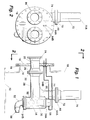
- Figure 1 is an elevational side view of a portion of the system for stirring and thereby reducing build up of bottom sediments in a storage tank showing the mechanism as mounted within the tank.
- a small portion of a tank is shown in dotted outline showing a manhole in the tank and a plate secured to the manhole by which the portions of the system that are interior of the tank can be supported above the tank floor.
- Figure 2 is an elevational view taken along the line 2-2 of Figure 1 showing the mechanism of the sediment removal system and without showing the tank structure so as to show more details of the apparatus used in the system.
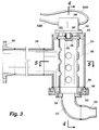
- Figure 3 is an enlarged elevational cross-sectional view of the major components employed interiorly of the tank as used in practicing the system of this invention.
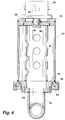
- Figure 4 is an enlarged elevational cross-sectional view as taken along the line 4-4 of Figure 3 showing the vertical outer casing and perforated inner casing in cross-section and showing the stepping motor mounted at the top of the outer casing.
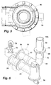
- Figure 5 is a fragmentary horizontal cross-sectional view taken along the line 5-5 of Figure 3 showing more details of the relationship between the horizontal tubular member, the vertically supported outer casing, the perforated inner casing and the nozzle as used in the system of this invention.
- Figure 6 is a partial isometric view showing the means of mounting the structure of Figure 1 to a plate that is secured to a tank manhole.
- Figure 6 shows the parallel relationship between the horizontal tubular member that supports the nozzle actuating portion of the system as it is arranged in parallel relationship with the fluid outlet piping by which tank fluid is drawn from out of the tank for recirculation.
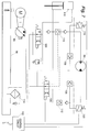
- Figure 7 is a hydraulic schematic showing an example of the schematic controls which may be employed for operation of the stepping motor by which the position of the nozzle can be stepped in increments to sweep substantially the entire tank bottom.
- Figure 8 shows an alternate arrangement for supporting the fluid inlet and outlet sections, the inlet section serving to discharge fluid through the rotated nozzle while the outlet section provides means for withdrawing fluid from the interior of the vessel.
- Figure 9 is a horizontal view as taken along the line 9-9 of Figure 8 showing the relationship between the fluid inlet and outlet sections of the apparatus.
- Figure 10 is an elevational exterior view as taken along 10-10 of Figure 8 showing a manhole cover plate with a fluid inlet and outlet conduit supported in the plate.
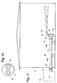
- Figure 11 is a reduced scale elevational view showing an alternate means of mounting the sludge removal system which permits the system to be positioned substantially centrally of the interior of a cylindrical tank with the horizontal tubular support member supported on the tank floor rather than being supported entirely by a plate affixed to a manhole as illustrated in Figures 1-6 and 8-10.
- Figure 1 illustrates a small section of a typically large diameter fluid storage tank, such as a crude oil storage tank.
- the tank has a cylindrical sidewall 10 and a horizontal bottom 12 and has a relatively large diameter opening 14 in sidewall 10 terminating at flange 16. Opening 14 is sometimes referred to as a "manhole" since openings of this size afford the possibility of entry and exit of workmen.
- Affixed to tank flange 16 is a cylindrical plate 18.
- the entire mechanism that is positioned within the interior of tank 10 is supported to plate 18.
- Figure 11 which will be discussed subsequently, shows an alternate embodiment wherein the employment of a large manhole plate 18 is not required.
- tubular inlet 20 Positioned in plate 18 and spaced apart side-by-side in paralleled relationship is horizontal tubular inlet 20 and tubular outlet member 22.
- tubular inlet member 20 has an exterior flange 24 and interior flange 26. Flanges 24 and 26 provide means for attachment of additional piping members as will be described.
- inlet pipe 20 Affixed to inlet pipe 20 is a horizontal tubular member 28 having a flange 30 that is secured to flange 26. Supported at the inner end 32 is a vertical outer casing 34 having an upper end 34A and lower end 34B, the lower end being supplied with a flange.
- a perforated inner casing 36 (best seen in Figures 3 and 5).
- plate 38 Secured to the upper end of inner casing 36 is plate 38 having a concentric socket 40. Plate 38 rotates within opening 42.
- An upper plate 44 is secured to the upper end of outer casing 34.
- tubular lower plate member 46 that rotates within opening 48 in an outer casing tubular plate 50.
- elbow 52 Secured to the tubular plate 50 is elbow 52 which may be accomplished by the use of a flange 54, and affixed to elbow 52 is an open-ended nozzle 56.
- nozzle 56 extends in a horizontal direction that is parallel to tank bottom 12 and is rotated as inner casing 36 is rotated (best seen in Figure 1).
- stepping motor 58 Affixed to upper plate 44 of vertical outer casing 34 is stepping motor 58. Extending downwardly from stepping motor 58 is shaft 60 that is received in socket 40, key 62 is employed to rotatably lock shaft 60 to socket 40 and to thereby lock the rotation of perforated inner casing 36 to shaft 60.
- Stepping motor 58 may be electrically activated by use of an electrical cable extending through the tank sidewall and controlled by circuitry external of the tank.
- a preferred means as illustrated employs a hydraulically actuated stepping motor with hydraulic fluid being supplied by conduits 64A and 64B.
- One type of hydraulic stepping motor 58 that can be used in practice of this invention is the type that uses a rack and pinion, wherein the rack is displaced by fluid acting on one or more hydraulic cylinders.
- a commercially available example of such product is available from the rotary actuator division of Parker Fluid Power Company of Wadsworth, Ohio and is referred to by this company as a "Hydraulic Rack and Pinion Rotary Actuator".
- stepping motor 58 incrementally rotationally advances shaft 60 to thereby rotationally incrementally position nozzle 56.
- hydraulic conduit 64A and 64B extends sealably through plate 38 to the exterior of vessel 10.
- outlet pipe 22 receives elbow 66 that turns upwardly and has flange 68. Attached by flange 72 to flange 68 is an open ended tubular extension 70. A tubular extension 74 is employed between elbow 66 and flange 68 to space the open end 70A of inlet pipe 70 a selected distance from the tank bottom 12.
- pump 76 is mounted exterior of tank 10 and may be motor or engine driven, a motor being indicated by the numeral 78. Fluid is withdrawn through outlet pipe 22 to pump 76 and injected back into the interior of the vessel through inlet pipe 20 for ultimate ejection through nozzle 56 to sweep a jet of fluid above the tank floor to loosen and re-suspend the sediments in the fluid.
- Figures 8, 9 and 10 show an alternate means of supporting the components making up the sludge removal system wherein the function is exactly the same except for the slight changes in piping.
- the main difference in the embodiment of Figures 8, 9 and 10 is that outlet pipe 22, as received in plate 18, is provided only with a short open-ended extension 80.
- angular bends 82 and 84 extend from inlet pipe 20 to flange 26 so that the horizontal tubular member 28 is supported more or less in direct alignment with plate 18.
- the arrangement of Figures 8, 9 and 10 simplify the installation and removal of the sludge removal system for repair and maintenance, however, the principal of operation of the arrangements of Figures 8, 9 and 10 is exactly the same as that described with reference to Figures 1-6.
- outlet pipe 22 has an exterior flange 86 that is adjacent to and parallel to inlet pipe exterior flange 24 to provide convenience for connection to the pump system as employed in the invention and as illustrated diagrammatically in Figure 6.
- Tank sidewall 10 and bottom 14 are illustrated as previously referenced.
- the tank is shown with a fixed roof, however, this is by way of example only as large diameter crude oil storage tanks frequently employ floating roofs.
- the vertical outer casing 34, that rotatably supports elbow 52, and nozzle 56 are positioned adjacent to the circumferential center of tank sidewall 10.
- nozzle 56 is placed at the top end of vertical outer casing 34 with stepping motor 58 positioned at the bottom end. This is arbitrary as the nozzle can be placed at the top or bottom either in the embodiment previously described or that in Figure 11.
- the primary difference in the embodiment of Figure 11 is that the structure is not supported from a plate secured to a manhole but is supported by a horizontal pipe 88 off of the tank floor 14 by means of pipe supports 90A and 90B.
- Pipe 88 extends sealably through the wall of the tank and is provided with an outer flange 24, as previously described, by which a pumping system may be connected to it.
- the pumping system is contained within an enclosure 92 having an outlet pipe 94.
- a fluid outlet system is required for the arrangement of Figure 11 the same as with the previously described arrangement but is not illustrated.
- the fluid outlet system may be in the form of a short length tubular extension, such as extension 80 shown in Figure 9 and therefore hidden from view in Figure 11.
- the particularly selected fluid outlet is the option of the operator and is not dependent upon whether the system of Figure 11 or the previously described systems are employed.
- Figure 7 shows a hydraulic schematic that can be used in practicing the invention.
- the schematic of Figure 7 is representative only since the control of stepping motor 58, whether electric or hydraulic, can be practiced in a number of ways.
- Figure 7 however illustrates one embodiment for providing hydraulic fluid to the stepping motor when it is hydraulically actuated, that is, when it is, as an example, of a cylindrical actuated rack and pinion arrangement.
- Tank 96 provides a source of hydraulic fluid. Hydraulic pressure is supplied by a variable volume piston pump 98. The direct flow of the hydraulic pressure is channelled by a solenoid operated direction control valve 100 in response to electrical signals supplied from a control circuit 102.
- the direction of fluid flow to the hydraulic rack and pinion rotary actuator 58 is controlled by means of a second solenoid operated direction control valve 104 which in turn is controlled by circuitry 102.
- Control valve 104 controls the actuation of pilot operated check valves 106, 108, 110 and 112 to direct the fluid flow to stepping motor 58.
- the flow of fluid ultimately returns through a filter 114 to tank 96.
- the quantity of fluid flow is channelled through a hydraulic cylinder 116 which can be utilized to apply limits on fluid flow to thereby determine the quantity of fluid passed to motor 58.
- Pressure actuated switches 118 and 120 provide signals to control circuit 102 for use in determining the signals to be applied to control valves 100 and 104.
- the hydraulic arrangement of Figure 7 is by way of example only as the stepping motor can be controlled externally of the tank in a variety of ways to produce incremental flows of hydraulic fluid to the stepping motor to advance the stepping motor output shaft in selectable increments of rotation and with the time delay for each incremented stepped position of the stepping motor shaft determined by timing signals provided by control circuit 102.
- the operator has full control over the method of use of the sludge removal system to adapt it to changing conditions and to the degree of sludge removal required for changing circumstances.
Landscapes
- Engineering & Computer Science (AREA)
- Mechanical Engineering (AREA)
- Chemical & Material Sciences (AREA)
- Chemical Kinetics & Catalysis (AREA)
- Cleaning In General (AREA)
- Mixers Of The Rotary Stirring Type (AREA)
Applications Claiming Priority (2)
| Application Number | Priority Date | Filing Date | Title |
|---|---|---|---|
| US08/276,270 US5445173A (en) | 1994-07-18 | 1994-07-18 | System for stirring and thereby reducing build up of bottom sediments in a storage tank |
| US276270 | 1994-07-18 |
Publications (1)
| Publication Number | Publication Date |
|---|---|
| EP0697252A1 true EP0697252A1 (de) | 1996-02-21 |
Family
ID=23055951
Family Applications (1)
| Application Number | Title | Priority Date | Filing Date |
|---|---|---|---|
| EP95304793A Withdrawn EP0697252A1 (de) | 1994-07-18 | 1995-07-10 | Rührsystem zur Verminderung der Bodensedimente in einem Speichertank |
Country Status (3)
| Country | Link |
|---|---|
| US (1) | US5445173A (de) |
| EP (1) | EP0697252A1 (de) |
| CA (1) | CA2154050C (de) |
Families Citing this family (16)
| Publication number | Priority date | Publication date | Assignee | Title |
|---|---|---|---|---|
| US5858252A (en) * | 1995-08-08 | 1999-01-12 | Darcy; Harold J. | Liquid purification system |
| DE69630766T2 (de) * | 1995-12-11 | 2004-09-23 | Taiho Industries Co., Ltd. | Verfahren zum Behandeln einer Flüssigkeit in einem Behälter und Flüssigkeitsstrahlvorrichtung zur Verwendung in dem Verfahren |
| US5876512A (en) * | 1996-10-07 | 1999-03-02 | Desormeaux; Thomas F. | Method and apparatus for cleaning pressure vessels while under operation |
| CN1131739C (zh) * | 1996-04-25 | 2003-12-24 | 太凤工业株式会社 | 处理油罐中液体的方法以及在该方法中使用的液体喷射装置 |
| DE29801934U1 (de) * | 1998-02-05 | 1998-03-26 | Oskar Vollmar GmbH, 70372 Stuttgart | Vorrichtung zur Strahlreinigung eines Abwasser enthaltenden Beckens |
| WO2000021693A1 (fr) * | 1998-10-12 | 2000-04-20 | Petrojet International | Dispositif et lance agitateur hydrodynamique |
| US6142160A (en) * | 1999-05-21 | 2000-11-07 | Betzdearborn Inc. | Method for dispersing and removing sludge contained in a storage tank |
| GB9915491D0 (en) * | 1999-07-02 | 1999-09-01 | Tooley John K | Resuspension apparatus for liquid storage tanks |
| WO2003022464A2 (en) * | 2001-09-07 | 2003-03-20 | Gunclean Toftejorg Ab | Equipment and use of the equipment for cleaning a tank space or preparation of drilling mud |
| GB2397996B (en) * | 2003-02-07 | 2005-01-19 | Willacy Oil Services Ltd | Sludge dispersal/inhibition in floating roof storage tanks |
| US20070084638A1 (en) * | 2005-10-19 | 2007-04-19 | Clyde Bohnsack | Drilling fluid flow facilitation |
| US9004381B2 (en) * | 2009-06-23 | 2015-04-14 | Zoeller Pump Company, Llc | Grinder pump basin system |
| US9592542B2 (en) * | 2012-04-26 | 2017-03-14 | Michael Henry James | Method and apparatus for cleaning the interior of an above ground storage tank |
| US10639685B2 (en) * | 2012-04-26 | 2020-05-05 | Michael Henry James | Method for maintaining solids in suspension in bulk storage tanks |
| CN111940433B (zh) * | 2020-07-29 | 2022-02-11 | 晶澳(邢台)太阳能有限公司 | 一种用于真空泵出油口的自动疏通装置和真空泵 |
| RU204478U1 (ru) * | 2021-01-22 | 2021-05-26 | Публичное акционерное общество "Транснефть" (ПАО "Транснефть") | Устройство для размыва донных отложений с выносным приводом поворота |
Citations (27)
| Publication number | Priority date | Publication date | Assignee | Title |
|---|---|---|---|---|
| US1978015A (en) | 1930-06-30 | 1934-10-23 | Peter M Erdman | Apparatus and method of cleaning tanks containing fluid |
| US2116935A (en) | 1932-10-10 | 1938-05-10 | Pyrate Corp Of Nevada | Apparatus for cleaning tanks and the like |
| US2647639A (en) | 1948-08-12 | 1953-08-04 | Raymond C Grein | Apparatus for cleaning tanks and the like |
| US2991203A (en) | 1957-10-31 | 1961-07-04 | Cornelis In T Veld | Method and apparatus for cleaning the interior of a tank |
| US3121027A (en) | 1963-02-26 | 1964-02-11 | Theodore E Ferris & Sons | Tank washing system |
| US3408006A (en) | 1965-10-22 | 1968-10-29 | Swimquip Inc | Liquid jet producing device |
| US3449772A (en) | 1967-07-24 | 1969-06-17 | Arthur W Werner | Automatically cycling swimming pool cleaning system |
| US3523647A (en) | 1968-09-11 | 1970-08-11 | Rain Bird Sprinkler Mfg | Part circle water motor driven sprinkler |
| US3542207A (en) | 1969-03-10 | 1970-11-24 | Dorr Oliver Inc | Sedimentation tank with rotary sediment raking structure |
| US3544012A (en) | 1968-08-26 | 1970-12-01 | Michael Mcnally | Pressure jet tank cleaner |
| US3586294A (en) | 1969-02-20 | 1971-06-22 | James J Strong | Method and apparatus for creating a suspension of fine particles in a liquid |
| US3675252A (en) | 1970-05-18 | 1972-07-11 | George J Ghiz | Pop-up head for water jet-pool cleaning system |
| US3704789A (en) | 1969-09-08 | 1972-12-05 | Dorr Oliver Inc | Continuous sedimentation tank with center-pier supported sediment raking apparatus |
| US3878857A (en) | 1972-05-09 | 1975-04-22 | Ulf Heibo | Apparatus for cleaning tanks and the like |
| US3895756A (en) | 1974-03-22 | 1975-07-22 | Ben E Jaeger | Method and apparatus for cleaning vessels |
| US3953226A (en) | 1974-07-24 | 1976-04-27 | The Molson Companies Limited | Tank cleaning apparatus |
| US4347979A (en) | 1977-10-20 | 1982-09-07 | Mathews Lester R | Swimming pool cleaner |
| US4407678A (en) | 1980-09-12 | 1983-10-04 | Butterworth Systems Inc. | Sludge removal machine |
| US4426233A (en) * | 1981-09-11 | 1984-01-17 | Taiho Industries Co. Ltd. | Method for disposal of sludge in floating roof type oil tank |
| DE8700079U1 (de) * | 1987-01-02 | 1988-04-28 | Oskar Vollmar GmbH, 7000 Stuttgart | Vorrichtung zur Strahlreinigung eines Regenbeckens |
| WO1989009662A1 (en) * | 1988-04-11 | 1989-10-19 | Serv-Tech, Inc. | Liquid circulator useful for dispersing sediment contained in a storage tank |
| EP0384690A1 (de) * | 1989-02-20 | 1990-08-29 | Breconcherry Limited | Reinigungsgerät für Behälter |
| US5078799A (en) | 1984-03-13 | 1992-01-07 | Fiprosa Holding | Process for recovering crude oil or refinery products from sludgy, thickened or sedimented products |
| US5091016A (en) | 1988-04-11 | 1992-02-25 | Serv-Tech, Inc. | Method for dispersing sediment contained in a storage tank |
| US5138741A (en) | 1990-06-13 | 1992-08-18 | Allen Henry W | Remote controlled sludge removal system |
| US5269041A (en) | 1990-06-13 | 1993-12-14 | Allen Henry W | Remote controlled sludge removal apparatus |
| WO1994017922A1 (en) * | 1993-02-15 | 1994-08-18 | Jan Berg Rasmussen | Tank cleaning system |
Family Cites Families (5)
| Publication number | Priority date | Publication date | Assignee | Title |
|---|---|---|---|---|
| US2714080A (en) * | 1952-12-31 | 1955-07-26 | Pyrate Sales Inc | Tank cleaning device and method |
| NL113419C (de) * | 1958-05-14 | 1900-01-01 | ||
| US3402725A (en) * | 1966-07-08 | 1968-09-24 | Werner Machinery Company | Bulk tank washing apparatus |
| NL7313470A (nl) * | 1973-10-01 | 1975-04-03 | Alfa Laval Nv | Roerinrichting voor een vloeistoftank. |
| US5107873A (en) * | 1989-08-08 | 1992-04-28 | Halliburton Company | Chamber cleaning apparatus and method |
-
1994
- 1994-07-18 US US08/276,270 patent/US5445173A/en not_active Expired - Lifetime
-
1995
- 1995-07-10 EP EP95304793A patent/EP0697252A1/de not_active Withdrawn
- 1995-07-17 CA CA002154050A patent/CA2154050C/en not_active Expired - Lifetime
Patent Citations (29)
| Publication number | Priority date | Publication date | Assignee | Title |
|---|---|---|---|---|
| US1978015A (en) | 1930-06-30 | 1934-10-23 | Peter M Erdman | Apparatus and method of cleaning tanks containing fluid |
| US2116935A (en) | 1932-10-10 | 1938-05-10 | Pyrate Corp Of Nevada | Apparatus for cleaning tanks and the like |
| US2647639A (en) | 1948-08-12 | 1953-08-04 | Raymond C Grein | Apparatus for cleaning tanks and the like |
| US2991203A (en) | 1957-10-31 | 1961-07-04 | Cornelis In T Veld | Method and apparatus for cleaning the interior of a tank |
| US3121027A (en) | 1963-02-26 | 1964-02-11 | Theodore E Ferris & Sons | Tank washing system |
| US3408006A (en) | 1965-10-22 | 1968-10-29 | Swimquip Inc | Liquid jet producing device |
| US3449772A (en) | 1967-07-24 | 1969-06-17 | Arthur W Werner | Automatically cycling swimming pool cleaning system |
| US3544012A (en) | 1968-08-26 | 1970-12-01 | Michael Mcnally | Pressure jet tank cleaner |
| US3523647A (en) | 1968-09-11 | 1970-08-11 | Rain Bird Sprinkler Mfg | Part circle water motor driven sprinkler |
| US3586294A (en) | 1969-02-20 | 1971-06-22 | James J Strong | Method and apparatus for creating a suspension of fine particles in a liquid |
| US3542207A (en) | 1969-03-10 | 1970-11-24 | Dorr Oliver Inc | Sedimentation tank with rotary sediment raking structure |
| US3704789A (en) | 1969-09-08 | 1972-12-05 | Dorr Oliver Inc | Continuous sedimentation tank with center-pier supported sediment raking apparatus |
| US3675252A (en) | 1970-05-18 | 1972-07-11 | George J Ghiz | Pop-up head for water jet-pool cleaning system |
| US3878857A (en) | 1972-05-09 | 1975-04-22 | Ulf Heibo | Apparatus for cleaning tanks and the like |
| US3895756A (en) | 1974-03-22 | 1975-07-22 | Ben E Jaeger | Method and apparatus for cleaning vessels |
| US3953226A (en) | 1974-07-24 | 1976-04-27 | The Molson Companies Limited | Tank cleaning apparatus |
| US4347979A (en) | 1977-10-20 | 1982-09-07 | Mathews Lester R | Swimming pool cleaner |
| US4407678A (en) | 1980-09-12 | 1983-10-04 | Butterworth Systems Inc. | Sludge removal machine |
| US4685974A (en) | 1980-09-12 | 1987-08-11 | Butterworth Systems, Inc. | Method for clearing settled sludge |
| US4426233A (en) * | 1981-09-11 | 1984-01-17 | Taiho Industries Co. Ltd. | Method for disposal of sludge in floating roof type oil tank |
| US5078799A (en) | 1984-03-13 | 1992-01-07 | Fiprosa Holding | Process for recovering crude oil or refinery products from sludgy, thickened or sedimented products |
| DE8700079U1 (de) * | 1987-01-02 | 1988-04-28 | Oskar Vollmar GmbH, 7000 Stuttgart | Vorrichtung zur Strahlreinigung eines Regenbeckens |
| WO1989009662A1 (en) * | 1988-04-11 | 1989-10-19 | Serv-Tech, Inc. | Liquid circulator useful for dispersing sediment contained in a storage tank |
| US4945933A (en) | 1988-04-11 | 1990-08-07 | Serv-Tech, Inc. | Liquid circulator useful for dispersing sediment contained in a storage tank |
| US5091016A (en) | 1988-04-11 | 1992-02-25 | Serv-Tech, Inc. | Method for dispersing sediment contained in a storage tank |
| EP0384690A1 (de) * | 1989-02-20 | 1990-08-29 | Breconcherry Limited | Reinigungsgerät für Behälter |
| US5138741A (en) | 1990-06-13 | 1992-08-18 | Allen Henry W | Remote controlled sludge removal system |
| US5269041A (en) | 1990-06-13 | 1993-12-14 | Allen Henry W | Remote controlled sludge removal apparatus |
| WO1994017922A1 (en) * | 1993-02-15 | 1994-08-18 | Jan Berg Rasmussen | Tank cleaning system |
Also Published As
| Publication number | Publication date |
|---|---|
| CA2154050A1 (en) | 1996-01-19 |
| US5445173A (en) | 1995-08-29 |
| CA2154050C (en) | 2006-10-10 |
Similar Documents
| Publication | Publication Date | Title |
|---|---|---|
| EP0697252A1 (de) | Rührsystem zur Verminderung der Bodensedimente in einem Speichertank | |
| EP1436099B1 (de) | Einrichtung und verwendung der einrichtung zur reinigung eines tankraums oder herstellung von bohrspülung | |
| JP2895126B2 (ja) | 貯蔵タンクに堆積された沈澱物を飛散する液体循環装置 | |
| US4685974A (en) | Method for clearing settled sludge | |
| US4546830A (en) | Methods and apparatus for recovery of hydrocarbons from underground water tables | |
| US6001242A (en) | Apparatus and method for high volume pipeline water filtration | |
| EP2121206B1 (de) | Verfahren und anlage zur behandlung von bodenschlamm in einem behälter | |
| EP0483180B1 (de) | In den boden versenkbare und über ein mannloch unmittelbar mit einem kraftstofflagerbehälter verbundene betankungsanlage | |
| CN115353190B (zh) | 一种嵌入式臭氧催化氧化装置及方法 | |
| CA2374607C (en) | Method for dispersing and removing sludge contained in a storage tank | |
| CA1241983A (en) | Fluid vibration apparatus | |
| US6973980B2 (en) | Petroleum drilling method and apparatus to cool and clean drill bit with recirculating fluid composition while reclaiming most water utilized and greatly reducing the normal consumption of water during drilling | |
| US20040050407A1 (en) | Apparatus for the automatic cleaning of liquid storage tanks | |
| GB2353230A (en) | Apparatus for the resuspension of solids in a crude oil storage tank | |
| RU2249269C2 (ru) | Пульсационный клапанный погружной насос (варианты) | |
| RU2220466C2 (ru) | Устройство для размыва осадка и дезактивации | |
| JPH0799032B2 (ja) | 汚水槽のスカム除去装置 | |
| CN1063717C (zh) | 储存液态产品的储罐 | |
| US3550163A (en) | Toilet construction | |
| EP1715965A1 (de) | Schwenk-strahlreiniger-mit fremdenergiefreiem schwenkantrieb | |
| CN1123401C (zh) | 油槽的清洁方法以及实现该方法的装置 | |
| CN2219748Y (zh) | 用于污(废)水再生的超声高能精滤器 | |
| CN224001761U (zh) | 路基淤泥就地固化装置 | |
| HK1035509B (en) | Method for cleaning an oil storage tank and device for implementing same | |
| EP0429841B1 (de) | Abscheider für mit Sink- und Schwimmstoffen befrachtete Abwässer |
Legal Events
| Date | Code | Title | Description |
|---|---|---|---|
| PUAI | Public reference made under article 153(3) epc to a published international application that has entered the european phase |
Free format text: ORIGINAL CODE: 0009012 |
|
| AK | Designated contracting states |
Kind code of ref document: A1 Designated state(s): BE CH DE DK ES FR GB GR IE IT LI NL PT SE |
|
| STAA | Information on the status of an ep patent application or granted ep patent |
Free format text: STATUS: THE APPLICATION IS DEEMED TO BE WITHDRAWN |
|
| 18D | Application deemed to be withdrawn |
Effective date: 19960822 |