EP0697255A2 - Méthode et appareil de poudrage électrostatique - Google Patents
Méthode et appareil de poudrage électrostatique Download PDFInfo
- Publication number
- EP0697255A2 EP0697255A2 EP95112883A EP95112883A EP0697255A2 EP 0697255 A2 EP0697255 A2 EP 0697255A2 EP 95112883 A EP95112883 A EP 95112883A EP 95112883 A EP95112883 A EP 95112883A EP 0697255 A2 EP0697255 A2 EP 0697255A2
- Authority
- EP
- European Patent Office
- Prior art keywords
- powder
- coated
- electrostatic
- gun
- electrode
- Prior art date
- Legal status (The legal status is an assumption and is not a legal conclusion. Google has not performed a legal analysis and makes no representation as to the accuracy of the status listed.)
- Withdrawn
Links
Images


Classifications
-
- B—PERFORMING OPERATIONS; TRANSPORTING
- B05—SPRAYING OR ATOMISING IN GENERAL; APPLYING FLUENT MATERIALS TO SURFACES, IN GENERAL
- B05B—SPRAYING APPARATUS; ATOMISING APPARATUS; NOZZLES
- B05B5/00—Electrostatic spraying apparatus; Spraying apparatus with means for charging the spray electrically; Apparatus for spraying liquids or other fluent materials by other electric means
- B05B5/025—Discharge apparatus, e.g. electrostatic spray guns
- B05B5/03—Discharge apparatus, e.g. electrostatic spray guns characterised by the use of gas, e.g. electrostatically assisted pneumatic spraying
- B05B5/032—Discharge apparatus, e.g. electrostatic spray guns characterised by the use of gas, e.g. electrostatically assisted pneumatic spraying for spraying particulate materials
-
- B—PERFORMING OPERATIONS; TRANSPORTING
- B05—SPRAYING OR ATOMISING IN GENERAL; APPLYING FLUENT MATERIALS TO SURFACES, IN GENERAL
- B05D—PROCESSES FOR APPLYING FLUENT MATERIALS TO SURFACES, IN GENERAL
- B05D1/00—Processes for applying liquids or other fluent materials
- B05D1/02—Processes for applying liquids or other fluent materials performed by spraying
- B05D1/04—Processes for applying liquids or other fluent materials performed by spraying involving the use of an electrostatic field
- B05D1/06—Applying particulate materials
-
- B—PERFORMING OPERATIONS; TRANSPORTING
- B05—SPRAYING OR ATOMISING IN GENERAL; APPLYING FLUENT MATERIALS TO SURFACES, IN GENERAL
- B05B—SPRAYING APPARATUS; ATOMISING APPARATUS; NOZZLES
- B05B5/00—Electrostatic spraying apparatus; Spraying apparatus with means for charging the spray electrically; Apparatus for spraying liquids or other fluent materials by other electric means
- B05B5/025—Discharge apparatus, e.g. electrostatic spray guns
- B05B5/047—Discharge apparatus, e.g. electrostatic spray guns using tribo-charging
-
- B—PERFORMING OPERATIONS; TRANSPORTING
- B05—SPRAYING OR ATOMISING IN GENERAL; APPLYING FLUENT MATERIALS TO SURFACES, IN GENERAL
- B05B—SPRAYING APPARATUS; ATOMISING APPARATUS; NOZZLES
- B05B5/00—Electrostatic spraying apparatus; Spraying apparatus with means for charging the spray electrically; Apparatus for spraying liquids or other fluent materials by other electric means
- B05B5/025—Discharge apparatus, e.g. electrostatic spray guns
- B05B5/053—Arrangements for supplying power, e.g. charging power
- B05B5/0533—Electrodes specially adapted therefor; Arrangements of electrodes
-
- B—PERFORMING OPERATIONS; TRANSPORTING
- B05—SPRAYING OR ATOMISING IN GENERAL; APPLYING FLUENT MATERIALS TO SURFACES, IN GENERAL
- B05B—SPRAYING APPARATUS; ATOMISING APPARATUS; NOZZLES
- B05B5/00—Electrostatic spraying apparatus; Spraying apparatus with means for charging the spray electrically; Apparatus for spraying liquids or other fluent materials by other electric means
- B05B5/08—Plant for applying liquids or other fluent materials to objects
- B05B5/087—Arrangements of electrodes, e.g. of charging, shielding, collecting electrodes
-
- B—PERFORMING OPERATIONS; TRANSPORTING
- B05—SPRAYING OR ATOMISING IN GENERAL; APPLYING FLUENT MATERIALS TO SURFACES, IN GENERAL
- B05B—SPRAYING APPARATUS; ATOMISING APPARATUS; NOZZLES
- B05B5/00—Electrostatic spraying apparatus; Spraying apparatus with means for charging the spray electrically; Apparatus for spraying liquids or other fluent materials by other electric means
- B05B5/08—Plant for applying liquids or other fluent materials to objects
- B05B5/12—Plant for applying liquids or other fluent materials to objects specially adapted for coating the interior of hollow bodies
Definitions
- the present invention relates to a method and an apparatus for electrostatic powder coating, whereby charged powder is electrostatically applied to the surface of an object to be coated, especially an object to be coated which has an undercoat insulating layer.
- electrostatic powder coating has been attracting attention as a nonpolluting coating method to replace solvent coating.
- the electrostatic powder coating is a method whereby powder, which is carried by air, is sprayed from an electrostatic gun toward a grounded object to be coated. The powder is charged before it is applied to the surface of the object to be coated.
- the method for charging such powder is divided roughly into types: in one type of the method, the powder is charged outside the electrostatic gun after it is sprayed from the electrostatic gun; in the other type, the powder is charged inside the electrostatic gun before it is sprayed from the electrostatic gun.
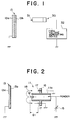
- a corona gun 1 is known as an electrostatic gun based on the external charging method.
- the tip of the corona gun 1 is provided with a pin-shaped corona electrode 2 to which high voltage is applied.
- An object to be coated 3 is grounded; therefore, when corona discharge is given from the tip of the gun 1 toward the object to be coated 3, causing powder to be carried by air and sprayed from the gun 1, the ions generated by the corona discharge adhere to the powder particles to charge them. After that, the charged powder particles adhere to the surface of the object to be coated 3 under the influences exerted by an air stream from the gun 1 and the electric force given along the lines of electric force 4.
- the lines of electric force 4 are concentrated on a projecting section of the object to be coated 3 and very few lines of electric force enter a recessed section due to the Faraday cage effect.
- the powder particles concentrate on and stick mainly to the projecting section.
- a powder particle layer 5 is formed mostly on the projecting section and it is hardly formed on the recessed section.
- the ions produced by the corona discharge barely half of them adhere to the powder particles and most ions stay as free ions and move along the lines of electric force 4 to adhere to the surface of the object to be coated 3.
- the free ions also accumulate on the object to be coated 3.
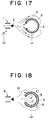
- a tribogun 9 shown in Fig. 18 is known as an electrostatic gun based on the internal charging method. Powder particles which are carried by air in the gun are charged by the friction with a charging material such as resin and after they are sprayed from the gun 9, they move on an air stream 10 and adhere to the surface of the object to be coated 3.
- a charging material such as resin
- the tribogun 9 no electrical field is generated between the gun 9 and the object to be coated 3; therefore, the charged powder particles are carried by the air stream 10 to the objected to be coated, without being influenced by electrical field.
- This causes the coating film 5 to be formed also on the recessed section of the object to be coated 3.
- no free ion problem which is observed with the corona gun, occurs.
- the object to be coated 3 consists of an iron sheet covered with an undercoat insulating layer and if a top coat layer is to be formed on the undercoat insulating layer, then forming the charged powder may cause the potential on the surface to rise easily, leading to the back ionization phenomenon.
- the efficiency of coating on the surface of the object to be coated 3 is lower than it is when the corona gun is used.
- a coating film for a motorcar is constituted by three or four multiple layers, the bottom layer being an electro-coat over which a primer surfacer and a base coat or a clear top coat are to be formed.
- the powder coating is applicable to the layers other than the electro-coat layer and the metallic base coat. Superimposing such coating films, however, incurs much more electrostatic restrictions than when coating a metallic object. This leads to such problems as lower transfer efficiency and a coating film with rough surface.
- the conventional electrostatic powder coating method presents the problems of the likelihood of the back ionization phenomenon which causes rough surfaces of coating films and of low transfer efficiency of the powder coating.
- the present invention has been achieved with a view toward solving the above problems. It is an object of the present invention to provide a method and an apparatus for electrostatic powder coating, whereby a good-quality coating surface can be formed while improving the transfer efficiency of the powder coating at the same time.
- an electrostatic powder coating method whereby charged powder supplied from a spray gun is applied to the surface of an electrically grounded object to be coated. Further, free ions in the vicinity of the spray gun are trapped and fine powder, which has a particle size of 25 ⁇ m or less, is electrostatically charged and applied to the surface of the object to be coated.
- an apparatus for electrostatic powder coating which is designed to electrostatically apply charged powder to the surface of an electrically grounded object to be coated.
- the apparatus is provided with an electrostatic gun for electrostatically charging fine-particle powder, which has a particle size of 25 ⁇ m or less, and spraying the charged powder to the surface of an object to be coated, and a free ion trapping device for trapping the free ions in the vicinity of the electrostatic gun.
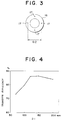
- An object to be coated 13 has an insulating layer 13b as an undercoat layer over the surface of an iron plate 13a which is grounded.
- the surface of the undercoat insulating layer 13 is exposed to an electrical field by using a corona discharging device 30 so as to precharge the surface.
- powder particles which have been negatively charged using a corona gun 11 shown in Fig. 2, are deposited on the undercoat insulating layer 13b; therefore, in this step, the undercoat insulating layer 13b is precharged with positive potential, i.e. it is precharged in the polarity which is opposite from that of the charged powder particles.
- the corona discharging device 30 is constructed by a corona electrode 31 and a high-voltage generating device 32 which applies positive high voltage to the corona electrode 31.
- An appropriate surface potential of the precharged undercoat insulating layer 13b can be selected by changing the applied voltage, the discharging distance, the discharging time, etc.; the surface potential is set for about 200 V to about 3 kV.
- the negatively charged powder is deposited on the surface of the undercoat insulating layer 13b of the object to be coated 13 by using the electrostatic powder coating apparatus shown in Fig. 2 so as to produce the top coat layer.
- the electrostatic powder coating apparatus is equipped with the corona gun 11 which employs the external charging method.
- the corona gun 11 has a cylindrical gun main body 11a; the central part of the tip of the gun main body 11a is provided with a pin-shaped corona electrode 12 for generating an electrical field outside the gun 11 so as to trigger corona discharge.
- a DC power source 15 connected applies high voltage to the corona electrode 12.
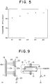
- a free ion trapping device 16 is provided behind the corona electrode 12 on the outer periphery of the gun main body 11a. As shown in Fig. 3, the free ion trapping device 16 has four grounded pin-shaped trapping electrodes 17 which are equidistantly installed on the same circumference having the central axis of the corona gun 11 as its center.
- the trapping electrodes 17 of the free ion trapping device 16 are provided near the corona electrode 12, lines of electric force 18 concentrate on the trapping electrodes 17 and the majority of the free ions generated in the vicinity of the corona electrode 12 move along the lines of electric force 18 and they are trapped by the trapping electrodes 17.
- the negative ions produced by the corona discharge adhere to the powder particles to negatively charge the powder particles.
- the negatively charged powder particles are guided primarily by an air stream to the object to be coated 13 and they adhere to the surface of the undercoat insulating layer 13b of the object to be coated 13.
- the positive charge constituting the surface potential of the undercoat insulating layer 13b and the negative charge of the charged powder particles countervail each other for neutralization, thus preventing the coated surface from developing such a high voltage that may cause back ionization.
- This allows a coating film with outstanding finish to be produced.
- fine powder which has a particle diameter of 5 to 20 ⁇ m as the powder.
- the undercoat insulating layer 13b may consist of two or more multiple layers rather than a single layer.
- Coating was carried out with different ion trapping distances D1 between the tip of the corona electrode 12 and the tips of the trapping electrodes 17 shown in Fig. 2.
- the measurement results of the transfer efficiency obtained with the different distances D1 are shown in Fig. 4.
- the gun voltage applied to the corona electrode 12 was set to -80 kV
- the distance between the tip of the corona electrode 12 and the object to be coated 13 was set to 200 mm
- the powder feedrate was set to 75 g/min.
- diameter D2 of the circle wherein the trapping electrodes 17 were installed as shown in Fig. 3 was set to 154 mm.
- the measurement results have revealed that good transfer efficiency is obtained at ion trapping distance D1 of 100 to 200 mm and that approximately 150 mm, in particular, provides the best result.
- the gun voltage applied to the corona electrode 12 was set to -80 kV
- the distance between the tip of the corona electrode 12 and the object to be coated 13 was set to 200 mm
- the discharge of the powder was set to 75 g/min.
- diameter D2 of the circle on which the trapping electrodes 17 are laid out preferably ranges from 100 to 200 mm and that the best transfer efficiency is obtained at 154 mm in particular. No marked difference was observed in the results of the measurement performed with four trapping electrodes 17 and eight trapping electrodes 17, respectively.
- a DC power supply may be provided to apply a potential to the trapping electrodes 17.
- a nozzle tip GN connected to a spray gun main body 110 is constructed by electrode covers 101a, 101b, and 101c which respectively incorporate protective resistors for safety, an inner cylinder 102 to which the electrode cover 101b is fixed with an electrode supporting member 103, a diffuser 104 which also serves as an electrode tip cover, a corona electrode 105 which is exposed 1 to 2 mm from the electrode tip cover 104, and an outer cylinder 106.
- the electrode covers 101a and 101b and the diffuser 104 are inserted in a power channel FR of the nozzle tip GN; the distal end of the diffuser 104 is located in a nozzle aperture 107.
- a section L of the powder channel FR where these members 101a, 101b, and 104 are installed is made narrower.
- the vertical cross-sectional area in the section L for carrying the coating is made 10% to 50% smaller than the radial cross-sectional area of a coating approach tube 109 so that the coating carrying speed increases in the section L.
- the side surface of the inner cylinder 102 is provided with a plurality of vortex air inlets 108a and 108b which are formed in the tangential direction with respect to the powder channel FR as shown in Fig. 7 and Fig. 8.
- An intersecting angle of the inlets 108a or 108b which are adjacent to each other is set to an appropriate value, e.g. to 60 degrees.
- compressed air A is supplied through the voltex air inlets 108a and 108b, which communicate with the powder approach tube 109, in order to clean the electrode cover 101c and the electrode supporting member 103.
- the free ion trapping device 16 which has a plurality of grounded trapping electrodes 17, is provided around the outer periphery of the electrostatic gun main body 110.
- fine-particle powder G having a particle diameter of 25 ⁇ m or less is carried into the channel FR by carrying air H and compressed air A is supplied through the vortex air inlets 108a and 108b.
- the stream S is accelerated due to the smaller aperture cross-sectional area in the section L, then it collides with the diffuser 104 which spreads conically.
- This causes the aggregated fine-particle G to be crushed and dispersed before it is sprayed through the nozzle aperture 107.
- the fine-particle G is negatively charged by the negative ions generated by the corona discharge, then it is sprayed to the object to be coated, thus producing a uniform coating film.
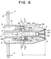
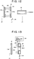
- Fig. 9 shows the structure of an electrostatic powder coating apparatus according to the third embodiment.
- the third embodiment has an electrical field generating electrode 21 which is provided between the corona gun 11 and the object to be coated 13 in the apparatus of the first embodiment shown in Fig. 2.
- the electrical field generating electrode 21 has a plurality of annular electrode members 23 which are laid out concentrically on the surface of an insulating plate 22 with an aperture 22a formed in the center thereof as illustrated in Fig. 10. These annular electrode members 23 are electrically connected with each other and also connected to a DC power supply 24 as shown in Fig. 9.
- the DC power supply 24 is connected to the annular electrode members 23 in a polarity which provides such an electrical field that causes the powder particles charged by the corona gun 11 are attracted to the object to be coated 13, i.e. in the same polarity as that of the DC power supply 15 connected to the corona electrode 12 of the corona gun 11.
- the DC power supply 15 applies a high voltage of about -80 kV, for example, to the corona electrode 12 of the corona gun 11 and the corona electrode 12 triggers corona discharge toward the object to be coated 13.
- the lines of electric force 18 concentrate onto the trapping electrodes 17 and most of the free ions generated near the corona electrode 12 move along the lines of electric force 18 until they are trapped by the trapping electrodes 17.
- a potential of about -20 kV to about -40 kV is applied from the DC power supply 24 to the plurality of annular electrode members 23 of the electrical field generating electrode 21, thereby generating a nearly uniform electrical field between the electrical field generating electrode 21 and the object to be coated 13.
- the ions produced by the corona discharge adhere to the powder particles to charge the powder particles which then move primarily on an air stream toward the electrical field generating electrode 21.
- the charged powder particles pass through the aperture 22a of the insulating plate 22 of the electrical field generating electrode 21 and are attracted to the object to be coated 13 under the influences exerted by the electrical field produced between the electrical field generating electrode 21 and the object to be coated 13, thereby adhering to the surface of the object to be coated 13.
- the third embodiment provides the following advantages: the number of free ions moving toward the object to be coated 13 is markedly reduced due to the presence of the free ion trapping device 16; the deterioration in the transfer efficiency due to an increase of the surface potential of the object to be coated 13 and the rough surface of a coating film caused by the back ionization phenomenon can be prevented; and the electrical field which is provided between the electrical field generating electrode 21 and the object to be coated 13 and which attracts charged powder particles makes it possible to improve the efficiency of coating the surface of the object to be coated 13 even if the number of free ions is decreased.
- a single wide planar electrode member may be used in place of the plurality of annular electrode members 23 of the electrical field generating electrode 21.
- the transfer efficiency was measured under different values of potential E applied to the electrical field generating electrode 21.
- the object to be coated 13 had a primer surfacer layer 13c which was comprised of a polyester powder and which was formed via the electrocoat layer 13b over the iron plate 13a.
- a top coat layer 13d composed of an acrylic resin powder, which had a mean particle diameter of 10 ⁇ m, was formed on the primer surfacer layer 13c.
- the top coat layer 13d was formed under five different conditions 1 to 5 using the corona gun 11. Only under condition 1, the measurement was performed without using the free ion trapping device 16. The voltage -80 kV applied to the corona electrode and the discharge 75.2 g/min.
- the ion trapping distance D1 between the tip of the corona electrode 12 and the tips of the trapping electrodes 17 was set to 150 mm and the diameter D2 of the circle on which the trapping electrodes 17 were installed was set to 154 mm.
- the distance d between the tip of the corona electrode 12 and the object to be coated was set to 200 mm or 150mm. Table 2 below shows the measurement results of the transfer efficiency.
- condition 3 wherein the potential of -20 kV was applied to the electrical field generating electrode, presents the highest transfer efficiency. Electrostatic repulsion was observed under condition 4 wherein the potential of -30 kV was applied to the electrical field generating electrode and under condition 5 wherein the potential of -40 kV was applied to the electrical field generating electrode.
- Fig. 12 shows the structure of the electrostatic powder coating apparatus according to the fourth embodiment.
- the fourth embodiment differs from the third embodiment in that it employs a tribogun 19, which utilizes frictional electrification, in place of the corona gun 11.
- the tribogun 19 includes a charging member composed of resin or the like, so that powder is charged by the friction with the charging member as it is transferred in the gun.
- the charging polarity is generally dependent on the type of material such as resin which is used as the charging member. For instance, when a charging member composed of Teflon is employed, the powder particles are charged to the positive polarity.
- the tribogun 19 shown in Fig. 12 is designed to charge powder particles to the positive polarity before spraying them.
- the DC power supply 24 is connected to the electrical field generating electrode 21 so that the polarity may be opposite from that in the case of the third embodiment.
- the undercoat insulating layer 13b of the object to be coated is precharged to the negative potential which is opposite from that of the charged powder particles.
- the positively charged powder which has been spreyed from the tribogun 19, moves on an air stream toward the induction field producing electrode 21 and passes through the aperture 22a of the insulating plate 22 until it reaches the induction field generated between the induction field producing electrode 21 and the object to be coated 13.
- the powder particles are drawn to the object to be coated 13 due to the electrical field and they adhere to the surface of the undercoat insulating layer 13b of the object to be coated 13.
- the negative charges constituting the surface potential of the undercoat insulating layer 13b and the positive charges of the charged powder particles cancel each other for neutralization.
- the coated surface does not develop such a high voltage that triggers the back ionization, thus enabling the formation of a coating film with outstanding finish.
- the electrical field which induces charged powder particles, is generated between the electrical field generating electrode 21 and the object to be coated 13. This makes it possible to efficiently coat the surface of the object to be coated 13 by using the tribogun 19 as the electrostatic gun.
- Fig. 13 shows an electrical field generating electrode 31 of an electrostatic powder coating apparatus according to the fifth embodiment.
- annular electrode members 23 are formed on a surface 32a of an insulating plate 32 made of a porous material.
- An air chamber 33 is formed on a rear surface 32b of the insulating plate 32, an air supplying device 34 being connected to the air chamber 33.
- compressed air is supplied from the air supplying device 34 to the air chamber 33 during coating operation.
- the air supplied to the air chamber 33 passes through the minute apertures of the porous material constituting the insulating plate 32 and comes from the rear surface 32b out to a front surface 32a of the insulating plate 32, then it is injected toward the object to be coated 13.
- This air jet keeps the annular electrode members 23 clean at all times, thus preventing the charged powder particles from sticking to the surfaces of the annular electrode members 23.
- porous material for the insulating plate 32 As the porous material for the insulating plate 32, a semi-sintered compact of a ceramic, polyethylene or the like may be used. Forming an air curtain by the air jetted from the insulating plate 32 to the object to be coated 13 makes it possible to keep the powder, which is prone to be blown away by the carrying air stream, inside the air curtain, thus further contributing to improved transfer efficiency.
- Fig. 14 shows an electrical field generating electrode 41 of an electrostatic powder coating apparatus according to the sixth embodiment.
- a predetermined potential is applied by a DC power supply 44 to a plurality of annular electrode members 43 formed on the surface of an insulating plate 42.
- an AC voltage is applied by an AC power supply 45 across the electrode members 43 which adjoin to each other.
- This construction enables an electrical field for inducing charged powder particles to be generated between the electrical field generating electrode 41 and the object to be coated 13 by the DC power supply 44.
- the application of the AC voltage across the adjacent annular electrode members 43 causes silent discharge on the surface of the electrical field generating electrode 41. The silent discharge prevents the charged powder particles from sticking to the surface of the annular electrode members 43.
- a gun 52 shown in Fig. 15, for linearly spraying powder is sometimes employed as the spray gun.
- parallel linear electrode members 53 shown in Fig. 16 may be used in place of the annular electrodes for the electrical field generating electrode.
- the safety can be improved by using a conductor such as resin wire containing carbon which has a resistance of about 100 M ⁇ to 1000 M ⁇ for the electrode members 23, 43, and 53 employed for the electrical field generating electrodes 21, 31, and 41.
- a conductor such as resin wire containing carbon which has a resistance of about 100 M ⁇ to 1000 M ⁇ for the electrode members 23, 43, and 53 employed for the electrical field generating electrodes 21, 31, and 41.
- An electrostatic powder coating method whereby free ions in the vicinity of a spray gun are trapped and the fine powder, which has a particle diameter of 25 ⁇ m or less, is electrostatically charged and applied to the surface of an electrically grounded object to be coated.
- An electrostatic powder coating apparatus which is equipped with an electrostatic gun for electrostatically charging fine powder, which has a particle diameter of 25 ⁇ m or less, and spraying the charged fine powder to the surface of the electrically grounded object to be coated, and a free ion trapping device for trapping free ions near the electrostatic gun.
Landscapes
- Electrostatic Spraying Apparatus (AREA)
- Application Of Or Painting With Fluid Materials (AREA)
Applications Claiming Priority (6)
| Application Number | Priority Date | Filing Date | Title |
|---|---|---|---|
| JP193265/94 | 1994-08-17 | ||
| JP19326594A JP3444664B2 (ja) | 1994-08-17 | 1994-08-17 | 静電粉体塗装方法 |
| JP193275/94 | 1994-08-17 | ||
| JP19327594A JPH0857364A (ja) | 1994-08-17 | 1994-08-17 | 静電粉体塗装装置 |
| JP194430/94 | 1994-08-18 | ||
| JP19443094A JPH0857361A (ja) | 1994-08-18 | 1994-08-18 | 静電粉体塗装方法及びその装置 |
Publications (2)
| Publication Number | Publication Date |
|---|---|
| EP0697255A2 true EP0697255A2 (fr) | 1996-02-21 |
| EP0697255A3 EP0697255A3 (fr) | 1996-12-18 |
Family
ID=27326735
Family Applications (1)
| Application Number | Title | Priority Date | Filing Date |
|---|---|---|---|
| EP95112883A Withdrawn EP0697255A3 (fr) | 1994-08-17 | 1995-08-16 | Méthode et appareil de poudrage électrostatique |
Country Status (2)
| Country | Link |
|---|---|
| EP (1) | EP0697255A3 (fr) |
| KR (1) | KR960007018A (fr) |
Cited By (8)
| Publication number | Priority date | Publication date | Assignee | Title |
|---|---|---|---|---|
| EP0745431A3 (fr) * | 1995-06-01 | 1998-12-16 | Nordson Corporation | Ensemble de montage pour pulvérisateur comprenant une contre-électrode |
| EP1056546A4 (fr) * | 1998-02-25 | 2002-08-28 | Nordson Corp | Pistolet pulverisateur a sonde anti-ionisation inverse dote d'un systeme de commande |
| US7159587B2 (en) | 2000-05-15 | 2007-01-09 | Resmed Limited | Respiratory mask having gas washout vent and gas washout vent assembly for respiratory mask |
| US7572488B2 (en) | 2003-07-22 | 2009-08-11 | Robert Bosch Gmbh | Method for applying an electrical insulation |
| EP1258704A3 (fr) * | 2001-05-17 | 2010-03-24 | Robert Bosch Gmbh | Dispositif de marquage pour réaliser des marques sur une surface |
| CN102806158A (zh) * | 2011-05-30 | 2012-12-05 | 张家港市佳龙真空浸漆设备制造厂 | 具有套杯结构的静电喷漆设备 |
| CN102806160A (zh) * | 2011-06-02 | 2012-12-05 | 张家港市佳龙真空浸漆设备制造厂 | 静电喷漆设备 |
| WO2023232199A3 (fr) * | 2022-06-03 | 2024-02-15 | P+S Pulverbeschichtungs- Und Staubfilteranlagen Gmbh | Procédé de distribution de poudre et buse de pulvérisation de poudre pour la mise en œuvre du procédé |
Citations (1)
| Publication number | Priority date | Publication date | Assignee | Title |
|---|---|---|---|---|
| EP0297520A2 (fr) * | 1987-07-01 | 1989-01-04 | Herberts Gesellschaft mit beschränkter Haftung | Procédé et dispositif pour vernir des pièces à surface électriquement isolante par application électrostatique ou par pulvérisation |
Family Cites Families (4)
| Publication number | Priority date | Publication date | Assignee | Title |
|---|---|---|---|---|
| FR2620354B2 (fr) * | 1987-02-12 | 1990-01-05 | Sames Sa | Dispositif de projection electrostatique de produit en poudre |
| DE4141663C2 (de) * | 1991-12-17 | 1996-09-19 | Wagner Int | Elektrostatische Pulver-Beschichtungspistole |
| FR2693923A1 (fr) * | 1992-07-24 | 1994-01-28 | Sames Sa | Dispositif de projection électrostatique de produit pulvérulent. |
| DE9305642U1 (de) * | 1993-04-15 | 1993-06-17 | Itw Gema Ag, St. Gallen | Elektrostatische Sprühvorrichtung |
-
1995
- 1995-08-14 KR KR1019950025020A patent/KR960007018A/ko not_active Ceased
- 1995-08-16 EP EP95112883A patent/EP0697255A3/fr not_active Withdrawn
Patent Citations (1)
| Publication number | Priority date | Publication date | Assignee | Title |
|---|---|---|---|---|
| EP0297520A2 (fr) * | 1987-07-01 | 1989-01-04 | Herberts Gesellschaft mit beschränkter Haftung | Procédé et dispositif pour vernir des pièces à surface électriquement isolante par application électrostatique ou par pulvérisation |
Cited By (8)
| Publication number | Priority date | Publication date | Assignee | Title |
|---|---|---|---|---|
| EP0745431A3 (fr) * | 1995-06-01 | 1998-12-16 | Nordson Corporation | Ensemble de montage pour pulvérisateur comprenant une contre-électrode |
| EP1056546A4 (fr) * | 1998-02-25 | 2002-08-28 | Nordson Corp | Pistolet pulverisateur a sonde anti-ionisation inverse dote d'un systeme de commande |
| US7159587B2 (en) | 2000-05-15 | 2007-01-09 | Resmed Limited | Respiratory mask having gas washout vent and gas washout vent assembly for respiratory mask |
| EP1258704A3 (fr) * | 2001-05-17 | 2010-03-24 | Robert Bosch Gmbh | Dispositif de marquage pour réaliser des marques sur une surface |
| US7572488B2 (en) | 2003-07-22 | 2009-08-11 | Robert Bosch Gmbh | Method for applying an electrical insulation |
| CN102806158A (zh) * | 2011-05-30 | 2012-12-05 | 张家港市佳龙真空浸漆设备制造厂 | 具有套杯结构的静电喷漆设备 |
| CN102806160A (zh) * | 2011-06-02 | 2012-12-05 | 张家港市佳龙真空浸漆设备制造厂 | 静电喷漆设备 |
| WO2023232199A3 (fr) * | 2022-06-03 | 2024-02-15 | P+S Pulverbeschichtungs- Und Staubfilteranlagen Gmbh | Procédé de distribution de poudre et buse de pulvérisation de poudre pour la mise en œuvre du procédé |
Also Published As
| Publication number | Publication date |
|---|---|
| EP0697255A3 (fr) | 1996-12-18 |
| KR960007018A (ko) | 1996-03-22 |
Similar Documents
| Publication | Publication Date | Title |
|---|---|---|
| CA1082911A (fr) | Appareil de revetement par pulverisation d'un brouillard electrostatique | |
| US4171100A (en) | Electrostatic paint spraying apparatus | |
| US4289278A (en) | Powder electro-charging device and electrostatic powder painting device | |
| US5584931A (en) | Electrostatic spray device | |
| KR100204972B1 (ko) | 회전무화두형 도장장치 | |
| RU2162374C2 (ru) | Аппарат для покрытия подложек индуктивно заряженными частицами порошка | |
| RU2162375C2 (ru) | Способ наведения электростатического заряда на порошки для использования таких порошков для изготовления покрытий | |
| US4347984A (en) | Electrostatic spray coating apparatus | |
| US4359192A (en) | Triboelectric powder spraying gun | |
| JPH0673646B2 (ja) | 摩擦電気粉末帯電による静電粉末噴射装置 | |
| US6230993B1 (en) | Method of charging using nonincendive rotary atomizer | |
| JPS59225762A (ja) | 遠心力で霧化された導電性塗料を誘導帯電する方法及び装置 | |
| US4774102A (en) | Method of electrostatic powder spray coating | |
| EP0697255A2 (fr) | Méthode et appareil de poudrage électrostatique | |
| US4084019A (en) | Electrostatic coating grid and method | |
| US7240861B2 (en) | Method and apparatus for dispensing paint powders for powder coatings | |
| US6276618B1 (en) | Electrostatic powder spray gun | |
| US5907469A (en) | Multiple charged developing gun | |
| US4316582A (en) | Device for painting by electrostatic powder spraying | |
| EP0627265A1 (fr) | Pistolet à charge tribo-électrique | |
| AU635792B2 (en) | Method and apparatus for electrostatically directing and depositing | |
| US4417696A (en) | Triboelectrification type electrostatic paint gun for paint in a powder form | |
| JP3747332B2 (ja) | 静電粉体塗装ガン | |
| JPH0857364A (ja) | 静電粉体塗装装置 | |
| Cross et al. | Observations during electrostatic deposition of high resistivity powders |
Legal Events
| Date | Code | Title | Description |
|---|---|---|---|
| PUAI | Public reference made under article 153(3) epc to a published international application that has entered the european phase |
Free format text: ORIGINAL CODE: 0009012 |
|
| AK | Designated contracting states |
Kind code of ref document: A2 Designated state(s): DE GB SE |
|
| PUAL | Search report despatched |
Free format text: ORIGINAL CODE: 0009013 |
|
| AK | Designated contracting states |
Kind code of ref document: A3 Designated state(s): DE GB SE |
|
| RAP1 | Party data changed (applicant data changed or rights of an application transferred) |
Owner name: NIPPON PAINT CO., LTD. Owner name: NIHON PARKERIZING CO., LTD. |
|
| 17P | Request for examination filed |
Effective date: 19970207 |
|
| 17Q | First examination report despatched |
Effective date: 19970602 |
|
| GRAP | Despatch of communication of intention to grant a patent |
Free format text: ORIGINAL CODE: EPIDOSNIGR1 |
|
| STAA | Information on the status of an ep patent application or granted ep patent |
Free format text: STATUS: THE APPLICATION IS DEEMED TO BE WITHDRAWN |
|
| 18D | Application deemed to be withdrawn |
Effective date: 20070222 |