EP0697272A2 - Procédé et dispositif pour la fabrication des baignoires composites - Google Patents
Procédé et dispositif pour la fabrication des baignoires composites Download PDFInfo
- Publication number
- EP0697272A2 EP0697272A2 EP95110909A EP95110909A EP0697272A2 EP 0697272 A2 EP0697272 A2 EP 0697272A2 EP 95110909 A EP95110909 A EP 95110909A EP 95110909 A EP95110909 A EP 95110909A EP 0697272 A2 EP0697272 A2 EP 0697272A2
- Authority
- EP
- European Patent Office
- Prior art keywords
- steel
- inner shell
- shell
- plastic
- frame
- Prior art date
- Legal status (The legal status is an assumption and is not a legal conclusion. Google has not performed a legal analysis and makes no representation as to the accuracy of the status listed.)
- Granted
Links
Images


Classifications
-
- B—PERFORMING OPERATIONS; TRANSPORTING
- B29—WORKING OF PLASTICS; WORKING OF SUBSTANCES IN A PLASTIC STATE IN GENERAL
- B29C—SHAPING OR JOINING OF PLASTICS; SHAPING OF MATERIAL IN A PLASTIC STATE, NOT OTHERWISE PROVIDED FOR; AFTER-TREATMENT OF THE SHAPED PRODUCTS, e.g. REPAIRING
- B29C70/00—Shaping composites, i.e. plastics material comprising reinforcements, fillers or preformed parts, e.g. inserts
- B29C70/68—Shaping composites, i.e. plastics material comprising reinforcements, fillers or preformed parts, e.g. inserts by incorporating or moulding on preformed parts, e.g. inserts or layers, e.g. foam blocks
- B29C70/84—Shaping composites, i.e. plastics material comprising reinforcements, fillers or preformed parts, e.g. inserts by incorporating or moulding on preformed parts, e.g. inserts or layers, e.g. foam blocks by moulding material on preformed parts to be joined
-
- A—HUMAN NECESSITIES
- A47—FURNITURE; DOMESTIC ARTICLES OR APPLIANCES; COFFEE MILLS; SPICE MILLS; SUCTION CLEANERS IN GENERAL
- A47K—SANITARY EQUIPMENT; ACCESSORIES THEREFOR, e.g. TOILET ACCESSORIES
- A47K3/00—Baths; Showers; Appurtenances therefor
- A47K3/02—Baths
-
- B—PERFORMING OPERATIONS; TRANSPORTING
- B29—WORKING OF PLASTICS; WORKING OF SUBSTANCES IN A PLASTIC STATE IN GENERAL
- B29C—SHAPING OR JOINING OF PLASTICS; SHAPING OF MATERIAL IN A PLASTIC STATE, NOT OTHERWISE PROVIDED FOR; AFTER-TREATMENT OF THE SHAPED PRODUCTS, e.g. REPAIRING
- B29C44/00—Shaping by internal pressure generated in the material, e.g. swelling or foaming ; Producing porous or cellular expanded plastics articles
- B29C44/02—Shaping by internal pressure generated in the material, e.g. swelling or foaming ; Producing porous or cellular expanded plastics articles for articles of definite length, i.e. discrete articles
- B29C44/12—Incorporating or moulding on preformed parts, e.g. inserts or reinforcements
- B29C44/14—Incorporating or moulding on preformed parts, e.g. inserts or reinforcements the preformed part being a lining
Definitions
- the present invention relates to a method and an apparatus for producing composite bathtubs with the features according to the preamble of the main claim.
- Composite bathtubs in the sense of the application can consist of an inner shell made of plastic and an outer shell made of steel with an intermediate filler. While the outer shell made of steel is used in particular for stabilization, the inner shell made of plastic should meet the sanitary requirements.
- the filler is said to improve stability and to provide heat and sound insulation.
- the object of the invention is to provide practical solutions for the economical production of composite bathtubs of this type.
- the plastic shell on the one hand and the steel shell on the other hand are first produced in a conventional manner in a mold corresponding to the bath, by deep-drawing, with the further necessary operations such as pickling, enamelling, etc. following.
- the plastic shell is first reversed, ie with the edge of the tub facing downwards, with its edge placed on the base plate of a clamping tool, it being positioned by a support frame.
- the prepared steel pan is then turned up and adjusted. Spacers ensure an even space between the two shells which is approximately 3 mm.
- the two trays are then clamped all around by a clamping tool.
- a sealing frame of this tool is designed so that the Continues space between the two shells all around next to the collar of the plastic shell in the form of a circumferential and sealed annular space that adjoins the space.
- the filler preferably polyurethane
- the filler is injected into the drain opening of the steel shell.
- the circumferential annular space next to the collar of the plastic tub is connected to a vacuum.
- the liquid plastic that is introduced at certain points is immediately pulled towards the edge by the vacuum, so that it is distributed evenly over the entire tub surface.
- the composite bathtubs consist of two interconnected shells, namely an inner shell made of plastic and an outer shell made of steel.
- an inner shell made of plastic and an outer shell made of steel.
- Claim 9 relates to a preferred device for performing this method.
- the outer shell is first formed from steel by deep drawing in a conventional manner. Small holes are drilled in this steel blank in the lower area. Then this steel blank is placed in a deformation drawing table which has a space below the steel blank which can be evacuated via a vacuum pump. A thermoplastic acrylic plate is then placed on the drawing table and clamped there by means of a frame which can consist of a lower frame and an upper frame and which can also be pivotable. When applying a vacuum, you can now pull the deformable acrylic sheet into the steel blank and adjust the contour of the tub, taking the steel blank beforehand an adhesive was applied so that the inner shell made of acrylic is glued to the outer shell made of steel and a good bond is produced.
- a reaction adhesive is preferably used as the adhesive, e.g. can be sprayed on and then activated by the heat contained in the acrylic plate when the acrylic plate comes into contact with the steel blank.
- a deformation drawing table is preferably used, which can be raised or lowered hydraulically, so that the tub rim can be formed into the plastic acrylic plate by a relative movement of the deformation drawing table relative to the frame by means of which the acrylic plate is clamped.
- Subclaim 9 has a device for content, which is preferably used to carry out the method according to this alternative of the invention.
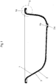
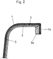
- 1 and 2 consists of an inner shell 1 made of plastic, for example acrylic, and the outside of an outer shell 2 made of steel.
- the space between the inner shell and outer shell, which is approximately in the 3 mm range, is filled with a filler 3, preferably made of polyurethane.
- a vertical collar 1a adjoins the horizontal edge, as can be seen in FIG. 2.
- the filler 3 also continues in this area through a collar 3a. However, such a collar is missing in the outer shell 2. Drain openings 1b and 2a are formed both on the inner shell and on the outer shell.
- both the inner shell and the outer shell are produced as blanks in the form shown in FIGS. 1 and 2 by deep drawing.
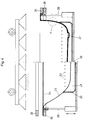
- a tensioning tool is provided, consisting of a base plate 10 with a support frame 11, a block frame 12, all around corresponding to the plan shape of the trough and a sealing frame 13 which is also rectangular in section and also runs all the way round.
- the method begins with the thermoformed, milled and cleaned inner shell 1 made of plastic with its edge placed on the base plate 10, the adapted support frame 11 being used for positioning.
- the collar 1a of the inner shell lies directly next to the surrounding block frame 12.
- the next step in the process is that the deep-drawn, pickled and enamelled outer shell 2 made of steel is turned over, as shown. It is adjusted in such a way that with the help of spacers between the two shells an even space remains in the 3mm range.
- Both shells are then clamped all around using a sealing frame 13 with a horizontal leg 13a and a vertical leg 13b.
- the horizontal leg 13a is supported on two sealing cords 17, which in turn lie on the block frame 12, a vacuum chamber 16 being formed between the sealing cords.
- the vertical leg 13b exerts pressure on the two shells 1 and 2 via a further sealing cord 15.
- a circumferential and sealed annular space 14 is formed between the vertical leg 13b and the collar 1a of the inner shell, which adjoins the space between the connects both shells.
- the annular space 14 is provided all around with vacuum connections 14a.
- the next process step consists of injecting polyurethane as a casting resin into the drain opening of the steel trough 2b, a vacuum being simultaneously generated via lines 14a in the annular space between the horizontal leg 13a and the collar 1a.
- the injected mass is distributed quickly and evenly in the space between the two shells. It also reaches the annular space 14 next to the collar 3a of the inner tub.
- FIGS. 4 and 5 In the following, reference is made to FIGS. 4 and 5 and a further alternative method according to the invention is explained.
- the steel blank 23 is deep drawn as before, the drain 27 is pushed through and drilled but without an overflow hole. Then a 1 mm Bohrung hole 22 is made in the radius-bottom wall, in the middle, for example by laser technology, approximately every 5 cm.
- the steel blank 23 is then pickled and passivated. Reaction adhesive is sprayed evenly and cleanly onto the entire inner surface of the steel trough 23. After the solvents have evaporated, the blank is then placed in a shaping drawing table 28. This can be moved hydraulically. All of the bores 22, including the drain hole 27, lie in an open vacuum channel 21, which fits the drawing table 28 with a precise fit. This channel is sealed to the tub body by a neoprene seal or the like.
- thermoplastic acrylic plate 24 is placed on the drawing table 28, directly over the inserted steel blank 23.
- a suitable apparatus for example a convection oven or quartz heater
- the plastic acrylic plate 24 is clamped hydraulically or pneumatically.
- the drawing table 28 is about 50 mm relative to the frame 25, 26 raised.
- the tub edge is formed into the clamped plastic acrylic plate by the downward movement.
- a vacuum pump installed on the tub rim immediately evacuates the air enclosed in the tub body via the bores 22. This pulls the soft acrylic plate 24 into the body of the steel blank 23 and adapts exactly to the tub contour.
- the reaction adhesive 30 is now activated by the heat still present in the acrylic.
- the outer shell 23 made of steel is preferably provided with an anti-rust layer 31 on the outside.
Landscapes
- Health & Medical Sciences (AREA)
- Public Health (AREA)
- Chemical & Material Sciences (AREA)
- Engineering & Computer Science (AREA)
- Composite Materials (AREA)
- Mechanical Engineering (AREA)
- Epidemiology (AREA)
- General Health & Medical Sciences (AREA)
- Laminated Bodies (AREA)
- Casting Or Compression Moulding Of Plastics Or The Like (AREA)
- Bathtubs, Showers, And Their Attachments (AREA)
- Moulding By Coating Moulds (AREA)
Applications Claiming Priority (4)
| Application Number | Priority Date | Filing Date | Title |
|---|---|---|---|
| DE4428896 | 1994-08-18 | ||
| DE4428896 | 1994-08-18 | ||
| DE4431716A DE4431716C3 (de) | 1994-08-18 | 1994-09-06 | Verfahren und Vorrichtung zur Herstellung von Verbund-Badewannen |
| DE4431716 | 1994-09-06 |
Publications (3)
| Publication Number | Publication Date |
|---|---|
| EP0697272A2 true EP0697272A2 (fr) | 1996-02-21 |
| EP0697272A3 EP0697272A3 (fr) | 1996-04-17 |
| EP0697272B1 EP0697272B1 (fr) | 1997-09-24 |
Family
ID=25939242
Family Applications (1)
| Application Number | Title | Priority Date | Filing Date |
|---|---|---|---|
| EP95110909A Expired - Lifetime EP0697272B1 (fr) | 1994-08-18 | 1995-07-12 | Procédé et dispositif pour la fabrication des baignoires composites |
Country Status (3)
| Country | Link |
|---|---|
| EP (1) | EP0697272B1 (fr) |
| AT (1) | ATE158534T1 (fr) |
| DE (1) | DE9422399U1 (fr) |
Cited By (3)
| Publication number | Priority date | Publication date | Assignee | Title |
|---|---|---|---|---|
| WO2001047695A1 (fr) * | 1999-12-23 | 2001-07-05 | Saab Ab | Dispositif de retenue destine a retenir un article et installation permettant le traitement thermique dudit article |
| DE4431716C3 (de) * | 1994-08-18 | 2003-04-10 | Kaldewei Franz Gmbh & Co | Verfahren und Vorrichtung zur Herstellung von Verbund-Badewannen |
| EP2025273A1 (fr) * | 2003-07-25 | 2009-02-18 | Kohler Mira Limited | Articles composites et procédé de fabrication |
Families Citing this family (1)
| Publication number | Priority date | Publication date | Assignee | Title |
|---|---|---|---|---|
| DE102009011170A1 (de) | 2009-03-04 | 2010-09-23 | Alape Gmbh | Badewanne und Verfahren zu ihrer Herstellung |
Citations (1)
| Publication number | Priority date | Publication date | Assignee | Title |
|---|---|---|---|---|
| DE2618070A1 (de) | 1976-04-24 | 1977-11-10 | Buderus Eisenwerk | Sanitaergegenstand, insbesondere badewanne |
Family Cites Families (8)
| Publication number | Priority date | Publication date | Assignee | Title |
|---|---|---|---|---|
| US3614793A (en) * | 1968-09-04 | 1971-10-26 | P I Nemiroff Corp The | Bathtub renovating apparatus and method |
| FR2087513A5 (en) * | 1970-05-21 | 1971-12-31 | Lienhard Lucien | Insulated baths - made of rigid foam filled grp shells incorporating support frames and covers for pumps etc |
| DE8031200U1 (de) * | 1980-11-24 | 1981-04-02 | Arts und Specials Kunsthandelsgesellschaft mbH, 7000 Stuttgart | Pass-wannen-einsatz fuer badewannen, duschbecken und waschrinnen |
| US4750967A (en) * | 1985-07-02 | 1988-06-14 | Kott John T | Molding a bathtub liner |
| FR2639580B1 (fr) * | 1988-11-25 | 1991-05-10 | Gigon Michel | Procede de realisation d'articles par coulee de beton polyester entre deux coques dont l'une est obtenue par thermoformage |
| FR2671307A1 (fr) * | 1991-01-08 | 1992-07-10 | Ciliento Maxime | Chassis transformable d'immobilisation d'une plaque thermoformable, a systeme de chauffage incorpore, et procede de revetement in-situ d'un element sanitaire pre-installe, a l'aide d'un tel chassis. |
| IT1260044B (it) * | 1992-03-30 | 1996-03-28 | Metodo di realizzazione di piatti-doccia, vasche da bagno, lavabi e turche in materiale plastico, e prodotti ottenuti | |
| JPH0625835A (ja) * | 1992-07-09 | 1994-02-01 | Kobe Steel Ltd | 真空蒸着方法及び真空蒸着装置 |
-
1994
- 1994-09-06 DE DE9422399U patent/DE9422399U1/de not_active Expired - Lifetime
-
1995
- 1995-07-12 EP EP95110909A patent/EP0697272B1/fr not_active Expired - Lifetime
- 1995-07-12 AT AT95110909T patent/ATE158534T1/de not_active IP Right Cessation
Patent Citations (1)
| Publication number | Priority date | Publication date | Assignee | Title |
|---|---|---|---|---|
| DE2618070A1 (de) | 1976-04-24 | 1977-11-10 | Buderus Eisenwerk | Sanitaergegenstand, insbesondere badewanne |
Cited By (4)
| Publication number | Priority date | Publication date | Assignee | Title |
|---|---|---|---|---|
| DE4431716C3 (de) * | 1994-08-18 | 2003-04-10 | Kaldewei Franz Gmbh & Co | Verfahren und Vorrichtung zur Herstellung von Verbund-Badewannen |
| WO2001047695A1 (fr) * | 1999-12-23 | 2001-07-05 | Saab Ab | Dispositif de retenue destine a retenir un article et installation permettant le traitement thermique dudit article |
| US6814563B2 (en) | 1999-12-23 | 2004-11-09 | Saab Ab | Holding device for holding an article and a plant for heat treatment of an article |
| EP2025273A1 (fr) * | 2003-07-25 | 2009-02-18 | Kohler Mira Limited | Articles composites et procédé de fabrication |
Also Published As
| Publication number | Publication date |
|---|---|
| ATE158534T1 (de) | 1997-10-15 |
| DE9422399U1 (de) | 2001-07-05 |
| EP0697272A3 (fr) | 1996-04-17 |
| EP0697272B1 (fr) | 1997-09-24 |
Similar Documents
| Publication | Publication Date | Title |
|---|---|---|
| DE2421021A1 (de) | Verfahren und vorrichtung zur herstellung von giessformen | |
| EP2802425B1 (fr) | Dispositif et procede d'emboutissage d'elements en forme de coque avec decoupe du fond et de la paroi integree | |
| DE3002560B1 (de) | Verfahren und Vorrichtung zum Hinterschaeumen von Weichschaum-Kunststoffolien mit Hartschaum-Kunststoff | |
| DE4034625C2 (fr) | ||
| DE3537997A1 (de) | Verfahren zur herstellung eines formteiles mit stoffverkleidung | |
| DE3420922A1 (de) | Maschine zur herstellung dreidimensionaler werkstuecke | |
| DE2523687C2 (de) | Vorrichtung zur Herstellung eines zusammengesetzten Behälters | |
| EP0697272A2 (fr) | Procédé et dispositif pour la fabrication des baignoires composites | |
| EP0024520B1 (fr) | Procédé pour la fabrication de profilés composites thermiquement isolants | |
| DE3603069C2 (fr) | ||
| DE19751759C1 (de) | Verfahren zur Herstellung einer Verbundwanne | |
| DE2848020A1 (de) | Verfahren zum herstellen einer sonnenblende, insbesondere fuer ein kraftfahrzeug, und form zur durchfuehrung des verfahrens | |
| DE4431716C2 (de) | Verfahren und Vorrichtung zur Herstellung von Verbund-Badewannen | |
| DE4030547A1 (de) | Verfahren zur herstellung eines konstruktionsbauteils und vorrichtung zur durchfuehrung des verfahrens | |
| WO2001087511A1 (fr) | Procede et outillage d'emboutissage profond | |
| DE3930526C2 (fr) | ||
| DE3413113A1 (de) | Verfahren und vorrichtung zum herstellen eines wasserkastens fuer einen waermetauscher, insbesondere fuer ein kraftfahrzeug, durch formen und derart hergestellter wasserkasten | |
| DE2611029A1 (de) | Verfahren zum herstellen gekruemmter, flexibler und im wesentlichen selbsttragender plattenfoermiger konstruktionen | |
| EP0776749A2 (fr) | Procédé et dispositif de fabrication de baignoires stratifiées | |
| EP0044882B1 (fr) | Procédé de fabrication en continu de profilés creux en métal remplis de mousse | |
| DE1299853B (de) | Verfahren und Vorrichtung zum Herstellen von duennwandigen Behaeltern mit eingestuelptem Boden durch Tiefziehen einer Folie aus thermoplastischem Kunststoff | |
| DE2655213A1 (de) | Verfahren und vorrichtung zum vakuum- bzw. unterdruckformen (tiefziehen) mittels eines eine tiefe ausnehmung aufweisenden modells | |
| DE4416346A1 (de) | Verfahren und Vorrichtung zum Herstellen eines Schwingungsdämpfers | |
| DE3116894A1 (de) | "verfahren zur herstellung von vorformteilen aus bindemittelhaltigen pressmassen, wie fasermatten, und vorrichtung zur durchfuehrung des verfahrens" | |
| CH679216A5 (en) | Laminar plate layer joining method - bends metal base layer edge over towards additional adhering layer |
Legal Events
| Date | Code | Title | Description |
|---|---|---|---|
| PUAI | Public reference made under article 153(3) epc to a published international application that has entered the european phase |
Free format text: ORIGINAL CODE: 0009012 |
|
| AK | Designated contracting states |
Kind code of ref document: A2 Designated state(s): AT BE CH DE ES FR GB LI LU NL |
|
| PUAL | Search report despatched |
Free format text: ORIGINAL CODE: 0009013 |
|
| AK | Designated contracting states |
Kind code of ref document: A3 Designated state(s): AT BE CH DE ES FR GB LI LU NL |
|
| 17P | Request for examination filed |
Effective date: 19960517 |
|
| 17Q | First examination report despatched |
Effective date: 19960807 |
|
| GRAG | Despatch of communication of intention to grant |
Free format text: ORIGINAL CODE: EPIDOS AGRA |
|
| GRAH | Despatch of communication of intention to grant a patent |
Free format text: ORIGINAL CODE: EPIDOS IGRA |
|
| GRAH | Despatch of communication of intention to grant a patent |
Free format text: ORIGINAL CODE: EPIDOS IGRA |
|
| GRAA | (expected) grant |
Free format text: ORIGINAL CODE: 0009210 |
|
| AK | Designated contracting states |
Kind code of ref document: B1 Designated state(s): AT BE CH DE ES FR GB LI LU NL |
|
| PG25 | Lapsed in a contracting state [announced via postgrant information from national office to epo] |
Ref country code: FR Free format text: LAPSE BECAUSE OF FAILURE TO SUBMIT A TRANSLATION OF THE DESCRIPTION OR TO PAY THE FEE WITHIN THE PRESCRIBED TIME-LIMIT Effective date: 19970924 Ref country code: ES Free format text: THE PATENT HAS BEEN ANNULLED BY A DECISION OF A NATIONAL AUTHORITY Effective date: 19970924 |
|
| REF | Corresponds to: |
Ref document number: 158534 Country of ref document: AT Date of ref document: 19971015 Kind code of ref document: T |
|
| REG | Reference to a national code |
Ref country code: CH Ref legal event code: EP |
|
| REF | Corresponds to: |
Ref document number: 59500710 Country of ref document: DE Date of ref document: 19971030 |
|
| GBT | Gb: translation of ep patent filed (gb section 77(6)(a)/1977) |
Effective date: 19971230 |
|
| EN | Fr: translation not filed | ||
| PLBE | No opposition filed within time limit |
Free format text: ORIGINAL CODE: 0009261 |
|
| STAA | Information on the status of an ep patent application or granted ep patent |
Free format text: STATUS: NO OPPOSITION FILED WITHIN TIME LIMIT |
|
| 26N | No opposition filed | ||
| REG | Reference to a national code |
Ref country code: GB Ref legal event code: IF02 |
|
| PGFP | Annual fee paid to national office [announced via postgrant information from national office to epo] |
Ref country code: NL Payment date: 20020619 Year of fee payment: 8 |
|
| PGFP | Annual fee paid to national office [announced via postgrant information from national office to epo] |
Ref country code: LU Payment date: 20020715 Year of fee payment: 8 |
|
| PGFP | Annual fee paid to national office [announced via postgrant information from national office to epo] |
Ref country code: BE Payment date: 20020724 Year of fee payment: 8 |
|
| PG25 | Lapsed in a contracting state [announced via postgrant information from national office to epo] |
Ref country code: LU Free format text: LAPSE BECAUSE OF NON-PAYMENT OF DUE FEES Effective date: 20030712 |
|
| PGFP | Annual fee paid to national office [announced via postgrant information from national office to epo] |
Ref country code: GB Payment date: 20030716 Year of fee payment: 9 |
|
| PGFP | Annual fee paid to national office [announced via postgrant information from national office to epo] |
Ref country code: CH Payment date: 20030718 Year of fee payment: 9 |
|
| PGFP | Annual fee paid to national office [announced via postgrant information from national office to epo] |
Ref country code: AT Payment date: 20030721 Year of fee payment: 9 |
|
| PG25 | Lapsed in a contracting state [announced via postgrant information from national office to epo] |
Ref country code: BE Free format text: LAPSE BECAUSE OF NON-PAYMENT OF DUE FEES Effective date: 20030731 |
|
| BERE | Be: lapsed |
Owner name: FRANZ *KALDEWEI G.M.B.H. & CO. Effective date: 20030731 |
|
| PG25 | Lapsed in a contracting state [announced via postgrant information from national office to epo] |
Ref country code: NL Free format text: LAPSE BECAUSE OF NON-PAYMENT OF DUE FEES Effective date: 20040201 |
|
| NLV4 | Nl: lapsed or anulled due to non-payment of the annual fee |
Effective date: 20040201 |
|
| PG25 | Lapsed in a contracting state [announced via postgrant information from national office to epo] |
Ref country code: GB Free format text: LAPSE BECAUSE OF NON-PAYMENT OF DUE FEES Effective date: 20040712 Ref country code: AT Free format text: LAPSE BECAUSE OF NON-PAYMENT OF DUE FEES Effective date: 20040712 |
|
| PG25 | Lapsed in a contracting state [announced via postgrant information from national office to epo] |
Ref country code: LI Free format text: LAPSE BECAUSE OF NON-PAYMENT OF DUE FEES Effective date: 20040731 Ref country code: CH Free format text: LAPSE BECAUSE OF NON-PAYMENT OF DUE FEES Effective date: 20040731 |
|
| GBPC | Gb: european patent ceased through non-payment of renewal fee |
Effective date: 20040712 |
|
| REG | Reference to a national code |
Ref country code: CH Ref legal event code: PL |
|
| PGFP | Annual fee paid to national office [announced via postgrant information from national office to epo] |
Ref country code: DE Payment date: 20060614 Year of fee payment: 12 |
|
| PG25 | Lapsed in a contracting state [announced via postgrant information from national office to epo] |
Ref country code: DE Free format text: LAPSE BECAUSE OF NON-PAYMENT OF DUE FEES Effective date: 20080201 |