EP0697285B1 - Système de réglage de la température pour une machine à imprimer - Google Patents
Système de réglage de la température pour une machine à imprimer Download PDFInfo
- Publication number
- EP0697285B1 EP0697285B1 EP95112446A EP95112446A EP0697285B1 EP 0697285 B1 EP0697285 B1 EP 0697285B1 EP 95112446 A EP95112446 A EP 95112446A EP 95112446 A EP95112446 A EP 95112446A EP 0697285 B1 EP0697285 B1 EP 0697285B1
- Authority
- EP
- European Patent Office
- Prior art keywords
- printing press
- temperature
- heat exchanger
- printing
- stabilizing system
- Prior art date
- Legal status (The legal status is an assumption and is not a legal conclusion. Google has not performed a legal analysis and makes no representation as to the accuracy of the status listed.)
- Expired - Lifetime
Links
- 238000007639 printing Methods 0.000 title claims description 73
- 238000007645 offset printing Methods 0.000 claims description 15
- 239000007788 liquid Substances 0.000 claims description 7
- 238000001816 cooling Methods 0.000 claims description 5
- 239000000498 cooling water Substances 0.000 claims description 5
- 230000000087 stabilizing effect Effects 0.000 claims 13
- 239000000110 cooling liquid Substances 0.000 claims 10
- 239000005871 repellent Substances 0.000 claims 1
- 239000002826 coolant Substances 0.000 description 17
- XLYOFNOQVPJJNP-UHFFFAOYSA-N water Substances O XLYOFNOQVPJJNP-UHFFFAOYSA-N 0.000 description 6
- 238000005057 refrigeration Methods 0.000 description 4
- 239000003507 refrigerant Substances 0.000 description 3
- 238000007664 blowing Methods 0.000 description 2
- 238000010438 heat treatment Methods 0.000 description 2
- 238000004378 air conditioning Methods 0.000 description 1
- 230000006835 compression Effects 0.000 description 1
- 238000007906 compression Methods 0.000 description 1
- 238000005265 energy consumption Methods 0.000 description 1
- 238000012423 maintenance Methods 0.000 description 1
- 238000000034 method Methods 0.000 description 1
- 238000005496 tempering Methods 0.000 description 1
- 238000011144 upstream manufacturing Methods 0.000 description 1
Images
Classifications
-
- B—PERFORMING OPERATIONS; TRANSPORTING
- B41—PRINTING; LINING MACHINES; TYPEWRITERS; STAMPS
- B41F—PRINTING MACHINES OR PRESSES
- B41F13/00—Common details of rotary presses or machines
- B41F13/08—Cylinders
- B41F13/22—Means for cooling or heating forme or impression cylinders
Definitions
- the invention relates to a printing press temperature control system according to the preamble of claim 1.
- Such a printing press temperature control system is over EP 0 602 312 A1. It is especially useful for the Fountain solution offset printing and dry offset printing used. This can be sheet printing (printing of individual sheets of paper) or roll printing (printing of paper webs).
- the sheet-fed offset printing machines are much smaller than the web offset presses stand in a pressroom and generate heat which they deliver to the pressroom.
- the chiller is working on the principle of alternate compression and Expansion of a refrigerant in one Refrigerant circuit:
- the refrigerant indicates its coldness the cold water or another coolant.
- the refrigeration generator releases the heat extracted from the cold water the surrounding area.
- the chiller hereinafter the chiller called, housed in the press room, where the Printing press is housed, however, at a distance of the printing press so that they can stand out from them do not heat each other.
- the object of the invention is to solve a problem unwanted heating of the Sheet printing machine, in particular Sheet offset printing machine by the heat given off by the refrigeration generator, and a unwanted heating of the refrigeration system by reduce heat radiated from the printing press, and train the tempering system at the same time so that it takes up less space in the pressroom and still is quickly and easily accessible for maintenance work or for an exchange of a device unit or for Refill fountain solution or another Liquid.
- the invention provides the following advantages in particular: The cooling generator requires less cooling capacity, in Pressroom becomes space for other purposes, and that Temperature control system is easily accessible.
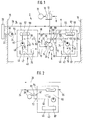
- the printing press temperature control system shown schematically in Fig. 1 2 is used to control the temperature of at least one press means of at least a printing unit 4 of a sheet-fed printing machine 6, especially one according to the offset printing process working sheet printing machine for printing on Sheets of paper.
- the printing machine means can be air 8 which by a blower 10 by a first Heat exchanger 12 driven through and on the Shell surface of a cylinder 13 to be cooled Printing machine 6 is blown.
- the cylinder 13 can for example a forme cylinder or plate cylinder Transfer cylinder such as a Blanket cylinder, or an impression cylinder.
- the Temperature control system 2 and the printing press 6 are in a press room 14 having walls 15 and 16.
- a Refrigerator 20 is outside the pressroom 14 arranged and cools coolant one through it passed coolant circuit 22.
- the Coolant circuit 22 extends through the a wall 15 in the press room 14 and has one the delivery branch 24 and the printing branch 14 one also passed through the press room 14 Return branch 26 on.
- the flow directions in Temperature control system 2 are indicated by arrows.
- Of the first heat exchanger 12 is at one end to the Lead branch 24 and with another end to the Return branch 26 connected in terms of flow and is through which the coolant flows.
- the first Form heat exchanger 12 and its associated fan 10 one to be cooled over the entire length of the Cylinder 13 extending blowing air cooling device, such as it is known for example from EP 0 602 312 A1.
- the printing unit 4 contains, for example, a forme cylinder or plate cylinder 28, a blanket cylinder 29 and an impression cylinder 30.
- a schematic shown dampening unit 32 transmits fountain solution a fountain solution 34 on the locations on the circumference of the Plate cylinder 28, which do not accept printing ink allowed to.
- a schematically illustrated inking unit 36 transfers ink from a not shown Ink source on the ink-accepting Places on the circumference of the plate cylinder 28.
- Figure 1 shows two device units 40 and 42, which immediately next to or below or into the printing press 6 can be placed within the printing room 14.
- Die one or first device unit 40 contains a second one Heat exchanger 44, a reservoir 46 for Fountain water 47, a pump 48 and a valve 50.
- the second heat exchanger 44 includes a first Heat exchanger strand 52, which over two Pipe connections 54 and 55 of the one unit 40 in the flow branch 24 of the coolant circuit 22 is used interchangeably so that it is from the Coolant of the coolant circuit 22 is flowed through.
- the second heat exchanger 44 contains also a second heat exchanger branch 58, which within the second heat exchanger 44 with the first Heat exchanger strand 52 is in heat exchange and over a heat exchanger feed line 60, in which the first pump 48 is located, and via a Heat exchanger return line 62 each with the Reservoir 46 is fluidly connected and with together a first temperature-controlled circuit 64 forms.
- a first temperature-controlled circuit 64 forms on a downstream of the first pump 48 located branch from the supply line 60.
- one Supply line 66 which contains the valve 50, which via a third pipe connection 67 one Device unit 40 with one in the fountain water tank 34 leading line section 68 connected in terms of flow is.
- a drain line 70 of an overflow of Dampening water pan 34 is via a fourth pipe connection 72 of one device unit 40 to a second Return line 74 connected in terms of flow, which opens into the reservoir 46.
- a second Return line 74 connected in terms of flow, which opens into the reservoir 46.
- the flow cross section of the valve 50 can be changed to more or less fountain solution to circulate in the second circuit 76.
- the Storage container 46 is designed such that it without Disassembly of the first pump 48 and the second Heat exchanger 44 from one device unit 40 can be removed or inserted.
- the other or second interchangeable device unit 42 is on, under or in the printing press 6, and in designed essentially the same as one or the first Device unit 40 and is therefore the same Provide reference numbers.
- unit 42 is not fountain solution 47 but cooling water 87, which by a Ink roller 88 is passed to it cool.
- the first heat exchanger strand 52 of the Heat exchanger 44 in the second device unit 42 is in the Lead branch 24 of the coolant circuit 22 in Row and downstream of the first heat exchanger strand 52 of the heat exchanger 44 of the first device unit 40 in this way arranged that he after the heat exchanger 44 of the first Unit 40 of the coolant Coolant circuit 22 is flowed through.
- the coolant of the coolant circuit 22 some heat from the fountain solution 47 of the first Unit 40 added before the cooling water 87th of the second device unit 42 cools. This will takes into account that the ink roller 88 be warmer must as the plate cylinder 28th
- a pump 90 Upstream of the heat exchanger 44 of the two Device units 40 and 42 are in the lead branch 24 of the coolant circuit 22, a pump 90, which the coolant through the Coolant circuit 22 promotes.
- the reservoir 46 of the two device units 40 and 42 are open at the top, so that in them Atmospheric pressure prevails.
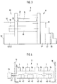
- Fig. 2 illustrated further embodiment of a Temperature control system according to the invention Storage container 46 of the second device unit 42 as be closed container in which the there is pressure generated by the pump 48. In this case no supply line 66 and no valve 50 are necessary, but the cooling water circuit is directly through the Ink roller 88 passed through, as Fig.2 shows.
- the two device units 40 and 42 either both on the operator side 91 of the Printing machine 6 under their stairs 92 or on the Drive side 93 of the printing press under gallery 94 the printing press 6 are placed under which also one or more drive motors 96 for driving of the plate cylinder 28, the blanket cylinder 29 and of the impression cylinder 30.
- the two device units 40 and 42 also for a single overall unit 40/42 be summarized. Instead of two device units 40 and 42 you only have one device 40/42.
- the rooms under the stairs 92 and / or the gallery 94 of the Printing machine 6 can be covered by walls and with a door 98 or 99 as access to the device units 40 and 42 may be provided.
- the device units 40 and 42 on other Place in or right next to the press 6 to be ordered. It is also possible to use one Device unit 40 on one machine side 91 or 93 and the other device unit 42 on the other To be arranged on machine side 93 or 91. Preferably be however, both device units 40 and 42 are on the same Machine side arranged.
- FIG. 4 shows a printing press 6 with four printing units 4. The two are located on each printing unit 4 Device units 40 and 42. On the Coolant circuit 22 of the refrigeration generator 20 are the device units 40 and 42 of all printing units in Flow connected in series or in parallel this other embodiment can have several Refrigerator 20 may be provided to each of the two Device units 40 and 42 or more of such Unit units 40 and 42 to cool.
Landscapes
- Engineering & Computer Science (AREA)
- Mechanical Engineering (AREA)
- Inking, Control Or Cleaning Of Printing Machines (AREA)
- Control Of Temperature (AREA)
Claims (11)
- Système de maintien à température modérée pour machine à imprimer, servant à maintenir à température modérée au moins un milieu (8, 47, 87) pour machines à imprimer, utilisé sur au moins un élément imprimant (4) d'une machine à imprimer des feuilles, en particulier d'une presse offset à feuilles, qui est conçue pour imprimer des feuilles et installée dans une salle d'impression (14), système qui comprend au moins un générateur de froid (20) pour refroidir au moins un liquide de refroidissement (en 22) qui est en relation d'échange thermique, à travers au moins une surface d'échange thermique (12, 44), avec le milieu (14, 47, 87) à tempérer dans la salle d'impression (14),
caractérisé en ce que le générateur de froid (20) est placé à l'extérieur de la salle d'impression (14) et que le liquide de refroidissement est amené à circuler, dans un circuit de liquide de refroidissement (22), à partir du générateur de froid (20) dans la salle d'impression (14), jusqu à la surface d'échange thermique (12, 44) du milieu (14, 47, 87) pour machines à imprimer, et de là, à l'extérieur de la salle d'impression (14), en retour jusqu'au générateur de froid (20). - Système de maintien à température modérée pour machine à imprimer selon la revendication 1, caractérisé en ce que le liquide de refroidissement du circuit de liquide de refroidissement (22) est amené à traverser au moins un échangeur de chaleur (12, 44) dans la salle d'impression (14) et que le milieu pour machines à imprimer est un liquide (47, 87) ou de l'air (8) amené à traverser l'échangeur de chaleur (44) séparément du liquide de refroidissement et en relation d'échange thermique avec ce liquide dans l'échangeur de chaleur (44).
- Système de maintien à température modérée pour machine à imprimer selon une des revendications précédentes, caractérisé en ce que la machine à imprimer est une presse offset à eau de mouillage (6) et que l'un au moins (47) des milieux pour machines à imprimer est de l'eau de mouillage qui est appliquée sur un cylindre de forme ou cylindre porte-plaque (28) de la machine à imprimer afin d'y former des zones répulsives à l'égard de l'encre.
- Système de maintien à température modérée pour machine à imprimer selon une des revendications précédentes, caractérisé en ce que l'un au moins des milieux pour machines à imprimer est un liquide (87) de maintien à température modérée, qui est amené à un corps rotatif (88) à refroidir de la machine à imprimer (6).
- Système de maintien à température modérée selon une des revendications précédentes, caractérisé en ce que l'un au moins des milieux pour machines à imprimer est de l'air (8) soufflé au moyen d'un ventilateur (10) sur un corps rotatif (14) à tempérer de la machine à imprimer (6).
- Système de maintien à température modérée pour machine à imprimer selon une des revendications 2 à 4, caractérisé en ce que chaque milieu liquide (47, 87) pour machines à imprimer est amené à circuler dans un circuit tempéré (76) qui lui est propre, comportant au moins l'un des échangeurs de chaleur (44), un réservoir (46) pour le milieu liquide (47, 87) pour machines à imprimer et une pompe (48) pour faire circuler le milieu liquide (47, 87) dans le circuit tempéré (76) concerné, et que, de chaque circuit (76) tempéré, au moins l'échangeur de chaleur (44), le réservoir (46) et la pompe (48) sont placés directement sur ou contre, au-dessous ou à l'intérieur de la machine à imprimer (6).
- Système de maintien à température modérée pour machine à imprimer selon la revendication 6, caractérisé en ce que, de chaque circuit tempéré (76), au moins l'échangeur de chaleur (44), le réservoir (46) et la pompe (48) sont placés sous un passage (92, 94) de la machine à imprimer (6) pouvant être emprunté par des personnes.
- Système de maintien à température modérée pour machine à imprimer selon la revendication 6 ou 7, caractérisé en ce que l'un au moins des circuits tempérés (76) présente une unité d'appareil (40, 42) dans laquelle sont logés son échangeur de chaleur (44), son réservoir (46) et sa pompe (48), et que l'unité d'appareil (40, 42), est réalisée comme un appareil pouvant être adjoint, lequel peut être adjoint selon les désirs à la machine à imprimer (6).
- Système de maintien à température modérée pour machine à imprimer selon la revendication 6 ou 7, caractérisé en ce qu'au moins deux circuits tempérés (76) présentent collectivement une unité d'appareil (40, 42), dans laquelle sont logés au moins leurs échangeurs de chaleur (44), leurs réservoirs (46) et leurs pompes (48), et que l'unité d'appareil (40/42) est réalisée comme un appareil pouvant être adjoint, lequel peut être adjoint selon les désirs à la machine à imprimer (6).
- Système de maintien à température modérée pour machine à imprimer selon une des revendications 6 à 9, caractérisé en ce qu'au moins deux milieux liquides différents (47, 87) pour machines à imprimer sont prévus, dont l'un est de l'eau de mouillage (47) et l'autre est de l'eau de refroidissement (87), et que les échangeurs de chaleur (44) de ces deux milieux (47, 87) pour machines à imprimer sont branchés en série, pour l'écoulement, dans le circuit de liquide de refroidissement (22) du générateur de froid (20), l'échangeur de chaleur (44) pour l'eau de refroidissement (87) étant disposé en aval de l'échangeur de chaleur (44) pour l'eau de mouillage (47), de sorte qu'il est seulement parcouru après ce dernier par le liquide de refroidissement du circuit de liquide de refroidissement (22).
- Système de maintien à température modérée pour machine à imprimer selon une des revendications 8 à 10, caractérisé en ce que le réservoir (46) est une sous-unité de l'unité d'appareil (40, 42) et peut être retiré ou mis en place dans celle-ci sans que cela demande le démontage de l'échangeur de chaleur (44) ou de la pompe (48).
Applications Claiming Priority (2)
| Application Number | Priority Date | Filing Date | Title |
|---|---|---|---|
| DE9413439U DE9413439U1 (de) | 1994-08-19 | 1994-08-19 | Druckmaschinen-Temperierungssystem |
| DE9413439U | 1994-08-19 |
Publications (4)
| Publication Number | Publication Date |
|---|---|
| EP0697285A2 EP0697285A2 (fr) | 1996-02-21 |
| EP0697285A3 EP0697285A3 (fr) | 1996-10-23 |
| EP0697285B1 true EP0697285B1 (fr) | 1998-06-17 |
| EP0697285B2 EP0697285B2 (fr) | 2005-02-09 |
Family
ID=6912629
Family Applications (1)
| Application Number | Title | Priority Date | Filing Date |
|---|---|---|---|
| EP95112446A Expired - Lifetime EP0697285B2 (fr) | 1994-08-19 | 1995-08-08 | Système de réglage de la température pour une machine à imprimer |
Country Status (2)
| Country | Link |
|---|---|
| EP (1) | EP0697285B2 (fr) |
| DE (2) | DE9413439U1 (fr) |
Families Citing this family (8)
| Publication number | Priority date | Publication date | Assignee | Title |
|---|---|---|---|---|
| DE4426083A1 (de) * | 1994-07-22 | 1996-01-25 | Baldwin Gegenheimer Gmbh | Druckmaschinen-Temperierungsvorrichtung |
| DE19516113A1 (de) * | 1995-05-05 | 1996-11-07 | Baldwin Gegenheimer Gmbh | Druckmaschinen-Temperiervorrichtung |
| DE19710124B4 (de) * | 1997-03-12 | 2006-03-16 | Goss Contiweb B.V. | Verfahren und Vorrichtung zur Temperierung von Kühlwalzen |
| DE29716582U1 (de) * | 1997-09-15 | 1997-11-06 | Technotrans GmbH, 48336 Sassenberg | Temperierungsanordnung bei Druckmaschinen |
| DE19857108A1 (de) | 1998-12-10 | 2000-06-15 | Baldwin Grafotec Gmbh | Temperiervorrichtung einer Druckmaschine |
| CN100532098C (zh) | 2004-07-16 | 2009-08-26 | 海德堡印刷机械股份公司 | 温度调节方法 |
| DE202008018546U1 (de) | 2008-02-19 | 2015-08-03 | Baldwin Germany Gmbh | Druckmaschinentemperiersystem |
| DE102008009996A1 (de) | 2008-02-19 | 2009-08-20 | Baldwin Germany Gmbh | Druckmaschinentemperiersystem |
Family Cites Families (5)
| Publication number | Priority date | Publication date | Assignee | Title |
|---|---|---|---|---|
| DE1953590C3 (de) * | 1969-10-24 | 1983-02-10 | Leo P.H. Dipl.Rer.Pol. 7000 Stuttgart Keller | Verfahren zur Beeinflussung des Flachdruckvorganges und Flachdruckmaschine hierfür |
| CH655690B (fr) * | 1982-05-19 | 1986-05-15 | ||
| GB2207636B (en) † | 1987-08-04 | 1991-08-14 | Seiichi Kurosawa | Thermoregulator |
| DE9017795U1 (de) * | 1990-10-08 | 1992-03-12 | MAN Roland Druckmaschinen AG, 6050 Offenbach | Thermoregler für eine um einen Druckformzylinder gelegte Druckform für wasserlosen Offset-Druck |
| DE4202544A1 (de) * | 1992-01-30 | 1993-08-05 | Baldwin Gegenheimer Gmbh | Druckplatten-temperierungssystem fuer eine druckmaschine |
-
1994
- 1994-08-19 DE DE9413439U patent/DE9413439U1/de not_active Expired - Lifetime
-
1995
- 1995-08-08 EP EP95112446A patent/EP0697285B2/fr not_active Expired - Lifetime
- 1995-08-08 DE DE59502566T patent/DE59502566D1/de not_active Expired - Lifetime
Also Published As
| Publication number | Publication date |
|---|---|
| EP0697285A3 (fr) | 1996-10-23 |
| EP0697285A2 (fr) | 1996-02-21 |
| DE59502566D1 (de) | 1998-07-23 |
| EP0697285B2 (fr) | 2005-02-09 |
| DE9413439U1 (de) | 1994-11-17 |
Similar Documents
| Publication | Publication Date | Title |
|---|---|---|
| EP0602312B1 (fr) | Système de refroidissement pour machines d'impression | |
| EP0652104B1 (fr) | Unité d'impression pour impression offset sans eau de mouillage | |
| EP0638418B1 (fr) | Système de refroidissement pour cylindres de machines d'impression | |
| EP0693372B1 (fr) | Dispositif de contrÔle de la température pour machines d'impression | |
| EP0480230B1 (fr) | Régulateur de température pour une forme d'impression disposée sur un cylindre de forme pour l'impression en offset saus eau | |
| DE4431188C2 (de) | Druckwerk für wasserlosen Offsetdruck | |
| EP2209631B1 (fr) | Système de thermorégulation pour machines à imprimer, à plusieurs niveaux de température | |
| EP0697285B1 (fr) | Système de réglage de la température pour une machine à imprimer | |
| EP1016521A1 (fr) | Dispositif de tempérage d'une machine d'impression | |
| EP0699525B1 (fr) | Système de refroidissement pour machines d'impression | |
| EP0693375B1 (fr) | Dispositif de régulation de la température pour une imprimante | |
| DE29608045U1 (de) | Anordnung zur Temperierung eines Feuchtmittels und/oder ausgewählter Walzen einer Druckmaschine | |
| DE19641031A1 (de) | Einrichtung zur Temperierung eines Druckwerkzylinders im Druckwerk einer Rotationsdruckmaschine | |
| DE4429520A1 (de) | Verfahren und Vorrichtung zur Temperierung von Temperierflüssigkeit in Druckmaschinen | |
| EP2326505B1 (fr) | Unité d impression et dispositifs et procédés de régulation de la température d'une unité d'impression | |
| EP1679186B1 (fr) | Rangement pour la distribution de fluides pour des machines d'impression offset | |
| DE9218193U1 (de) | Druckmaschinen-Temperierungssystem | |
| EP1238802B1 (fr) | Dispositif d'alimentation de solution de mouillage | |
| DE29520464U1 (de) | Anordnung zur Temperierung eines Feuchtmittels und/oder ausgewählter Walzen einer Druckmaschine | |
| DE9314968U1 (de) | Temperierungssystem für Druckmaschinenzylinder | |
| DE102008009996A1 (de) | Druckmaschinentemperiersystem | |
| DE102018113959A1 (de) | Druckmaschinen-temperierungsvorrichtung und verfahren zum temperieren von farbwerken und von feuchtmittel einer offset-druckmaschine | |
| DE20113397U1 (de) | Druckmaschinen-Flüssigkeitsversorgungsgerät | |
| DE202008018546U1 (de) | Druckmaschinentemperiersystem | |
| EP1833675A1 (fr) | Procédé de réglage de transfert d'encre d'imprimerie |
Legal Events
| Date | Code | Title | Description |
|---|---|---|---|
| PUAI | Public reference made under article 153(3) epc to a published international application that has entered the european phase |
Free format text: ORIGINAL CODE: 0009012 |
|
| 17P | Request for examination filed |
Effective date: 19950808 |
|
| AK | Designated contracting states |
Kind code of ref document: A2 Designated state(s): DE FR GB IT |
|
| PUAL | Search report despatched |
Free format text: ORIGINAL CODE: 0009013 |
|
| AK | Designated contracting states |
Kind code of ref document: A3 Designated state(s): DE FR GB IT |
|
| RAP1 | Party data changed (applicant data changed or rights of an application transferred) |
Owner name: BALDWIN GRAFOTEC GMBH |
|
| GRAG | Despatch of communication of intention to grant |
Free format text: ORIGINAL CODE: EPIDOS AGRA |
|
| GRAG | Despatch of communication of intention to grant |
Free format text: ORIGINAL CODE: EPIDOS AGRA |
|
| GRAH | Despatch of communication of intention to grant a patent |
Free format text: ORIGINAL CODE: EPIDOS IGRA |
|
| 17Q | First examination report despatched |
Effective date: 19971111 |
|
| ITF | It: translation for a ep patent filed | ||
| GRAH | Despatch of communication of intention to grant a patent |
Free format text: ORIGINAL CODE: EPIDOS IGRA |
|
| GRAA | (expected) grant |
Free format text: ORIGINAL CODE: 0009210 |
|
| AK | Designated contracting states |
Kind code of ref document: B1 Designated state(s): DE FR GB IT |
|
| PG25 | Lapsed in a contracting state [announced via postgrant information from national office to epo] |
Ref country code: FR Free format text: LAPSE BECAUSE OF NON-PAYMENT OF DUE FEES Effective date: 19980617 |
|
| GBT | Gb: translation of ep patent filed (gb section 77(6)(a)/1977) |
Effective date: 19980618 |
|
| REF | Corresponds to: |
Ref document number: 59502566 Country of ref document: DE Date of ref document: 19980723 |
|
| ET | Fr: translation filed | ||
| PLBI | Opposition filed |
Free format text: ORIGINAL CODE: 0009260 |
|
| PLAV | Examination of admissibility of opposition |
Free format text: ORIGINAL CODE: EPIDOS OPEX |
|
| 26 | Opposition filed |
Opponent name: HEIDELBERGER DRUCKMASCHINEN AG Effective date: 19990317 |
|
| PLAV | Examination of admissibility of opposition |
Free format text: ORIGINAL CODE: EPIDOS OPEX |
|
| PLBF | Reply of patent proprietor to notice(s) of opposition |
Free format text: ORIGINAL CODE: EPIDOS OBSO |
|
| PLBF | Reply of patent proprietor to notice(s) of opposition |
Free format text: ORIGINAL CODE: EPIDOS OBSO |
|
| REG | Reference to a national code |
Ref country code: GB Ref legal event code: IF02 |
|
| PLAW | Interlocutory decision in opposition |
Free format text: ORIGINAL CODE: EPIDOS IDOP |
|
| APAC | Appeal dossier modified |
Free format text: ORIGINAL CODE: EPIDOS NOAPO |
|
| APAC | Appeal dossier modified |
Free format text: ORIGINAL CODE: EPIDOS NOAPO |
|
| RAP2 | Party data changed (patent owner data changed or rights of a patent transferred) |
Owner name: BALDWIN GERMANY GMBH |
|
| PGFP | Annual fee paid to national office [announced via postgrant information from national office to epo] |
Ref country code: GB Payment date: 20030715 Year of fee payment: 9 |
|
| PGFP | Annual fee paid to national office [announced via postgrant information from national office to epo] |
Ref country code: FR Payment date: 20030819 Year of fee payment: 9 |
|
| PG25 | Lapsed in a contracting state [announced via postgrant information from national office to epo] |
Ref country code: GB Free format text: LAPSE BECAUSE OF NON-PAYMENT OF DUE FEES Effective date: 20040808 |
|
| APBU | Appeal procedure closed |
Free format text: ORIGINAL CODE: EPIDOSNNOA9O |
|
| PUAH | Patent maintained in amended form |
Free format text: ORIGINAL CODE: 0009272 |
|
| STAA | Information on the status of an ep patent application or granted ep patent |
Free format text: STATUS: PATENT MAINTAINED AS AMENDED |
|
| APAA | Appeal reference recorded |
Free format text: ORIGINAL CODE: EPIDOS REFN |
|
| 27A | Patent maintained in amended form |
Effective date: 20050209 |
|
| AK | Designated contracting states |
Kind code of ref document: B2 Designated state(s): DE FR GB IT |
|
| GBPC | Gb: european patent ceased through non-payment of renewal fee |
Effective date: 20040808 |
|
| REG | Reference to a national code |
Ref country code: FR Ref legal event code: ST |
|
| PG25 | Lapsed in a contracting state [announced via postgrant information from national office to epo] |
Ref country code: IT Free format text: LAPSE BECAUSE OF NON-PAYMENT OF DUE FEES;WARNING: LAPSES OF ITALIAN PATENTS WITH EFFECTIVE DATE BEFORE 2007 MAY HAVE OCCURRED AT ANY TIME BEFORE 2007. THE CORRECT EFFECTIVE DATE MAY BE DIFFERENT FROM THE ONE RECORDED. Effective date: 20050808 |
|
| APAH | Appeal reference modified |
Free format text: ORIGINAL CODE: EPIDOSCREFNO |
|
| EN | Fr: translation not filed | ||
| PGFP | Annual fee paid to national office [announced via postgrant information from national office to epo] |
Ref country code: DE Payment date: 20120816 Year of fee payment: 18 |
|
| PG25 | Lapsed in a contracting state [announced via postgrant information from national office to epo] |
Ref country code: DE Free format text: LAPSE BECAUSE OF NON-PAYMENT OF DUE FEES Effective date: 20140301 |
|
| REG | Reference to a national code |
Ref country code: DE Ref legal event code: R119 Ref document number: 59502566 Country of ref document: DE Effective date: 20140301 |