EP0697290A1 - Presse offset à plusieurs couleurs utilisant d'encre aqueuse et plaques d'impression à sec avec stations intermédiaires de séchage et d'extraction - Google Patents
Presse offset à plusieurs couleurs utilisant d'encre aqueuse et plaques d'impression à sec avec stations intermédiaires de séchage et d'extraction Download PDFInfo
- Publication number
- EP0697290A1 EP0697290A1 EP95305671A EP95305671A EP0697290A1 EP 0697290 A1 EP0697290 A1 EP 0697290A1 EP 95305671 A EP95305671 A EP 95305671A EP 95305671 A EP95305671 A EP 95305671A EP 0697290 A1 EP0697290 A1 EP 0697290A1
- Authority
- EP
- European Patent Office
- Prior art keywords
- printing
- ink
- aqueous
- substrate
- press
- Prior art date
- Legal status (The legal status is an assumption and is not a legal conclusion. Google has not performed a legal analysis and makes no representation as to the accuracy of the status listed.)
- Withdrawn
Links
- 238000007639 printing Methods 0.000 claims abstract description 242
- 239000000758 substrate Substances 0.000 claims abstract description 60
- 238000000034 method Methods 0.000 claims abstract description 30
- 238000007645 offset printing Methods 0.000 claims abstract description 29
- 230000002209 hydrophobic effect Effects 0.000 claims abstract description 19
- 238000001035 drying Methods 0.000 claims abstract description 17
- 238000012546 transfer Methods 0.000 claims description 15
- 239000000463 material Substances 0.000 claims description 13
- 238000009736 wetting Methods 0.000 claims description 4
- 238000007599 discharging Methods 0.000 claims 7
- 230000005661 hydrophobic surface Effects 0.000 claims 4
- 230000001846 repelling effect Effects 0.000 claims 1
- XLYOFNOQVPJJNP-UHFFFAOYSA-N water Substances O XLYOFNOQVPJJNP-UHFFFAOYSA-N 0.000 abstract description 23
- 238000001459 lithography Methods 0.000 abstract description 6
- 239000003039 volatile agent Substances 0.000 abstract description 5
- 238000000605 extraction Methods 0.000 abstract description 3
- 239000000976 ink Substances 0.000 description 128
- 239000003921 oil Substances 0.000 description 23
- VYPSYNLAJGMNEJ-UHFFFAOYSA-N Silicium dioxide Chemical compound O=[Si]=O VYPSYNLAJGMNEJ-UHFFFAOYSA-N 0.000 description 16
- 239000000243 solution Substances 0.000 description 10
- 238000000576 coating method Methods 0.000 description 9
- 230000008569 process Effects 0.000 description 9
- 230000003197 catalytic effect Effects 0.000 description 8
- 239000011248 coating agent Substances 0.000 description 8
- 239000010410 layer Substances 0.000 description 8
- 239000000377 silicon dioxide Substances 0.000 description 8
- 235000012239 silicon dioxide Nutrition 0.000 description 8
- 229910052782 aluminium Inorganic materials 0.000 description 6
- XAGFODPZIPBFFR-UHFFFAOYSA-N aluminium Chemical compound [Al] XAGFODPZIPBFFR-UHFFFAOYSA-N 0.000 description 6
- 239000002904 solvent Substances 0.000 description 6
- CIWBSHSKHKDKBQ-JLAZNSOCSA-N Ascorbic acid Chemical compound OC[C@H](O)[C@H]1OC(=O)C(O)=C1O CIWBSHSKHKDKBQ-JLAZNSOCSA-N 0.000 description 5
- 239000012298 atmosphere Substances 0.000 description 5
- 238000009835 boiling Methods 0.000 description 5
- 239000007788 liquid Substances 0.000 description 5
- LYCAIKOWRPUZTN-UHFFFAOYSA-N Ethylene glycol Chemical compound OCCO LYCAIKOWRPUZTN-UHFFFAOYSA-N 0.000 description 4
- 238000001704 evaporation Methods 0.000 description 4
- 230000008020 evaporation Effects 0.000 description 4
- 239000002480 mineral oil Substances 0.000 description 4
- 230000001681 protective effect Effects 0.000 description 4
- 230000008901 benefit Effects 0.000 description 3
- 239000003086 colorant Substances 0.000 description 3
- 238000009434 installation Methods 0.000 description 3
- 229910052751 metal Inorganic materials 0.000 description 3
- 239000002184 metal Substances 0.000 description 3
- 239000000049 pigment Substances 0.000 description 3
- 238000000926 separation method Methods 0.000 description 3
- 231100000331 toxic Toxicity 0.000 description 3
- 230000002588 toxic effect Effects 0.000 description 3
- 230000009102 absorption Effects 0.000 description 2
- 238000010521 absorption reaction Methods 0.000 description 2
- 238000013459 approach Methods 0.000 description 2
- 229920002678 cellulose Polymers 0.000 description 2
- 239000003795 chemical substances by application Substances 0.000 description 2
- 238000001816 cooling Methods 0.000 description 2
- 239000003085 diluting agent Substances 0.000 description 2
- 239000000975 dye Substances 0.000 description 2
- 239000007789 gas Substances 0.000 description 2
- WGCNASOHLSPBMP-UHFFFAOYSA-N hydroxyacetaldehyde Natural products OCC=O WGCNASOHLSPBMP-UHFFFAOYSA-N 0.000 description 2
- 239000011236 particulate material Substances 0.000 description 2
- 230000000717 retained effect Effects 0.000 description 2
- 238000006467 substitution reaction Methods 0.000 description 2
- 239000002562 thickening agent Substances 0.000 description 2
- 229920002472 Starch Polymers 0.000 description 1
- 229910000831 Steel Inorganic materials 0.000 description 1
- 230000002745 absorbent Effects 0.000 description 1
- 239000002250 absorbent Substances 0.000 description 1
- 229920000615 alginic acid Polymers 0.000 description 1
- 235000010443 alginic acid Nutrition 0.000 description 1
- 230000004075 alteration Effects 0.000 description 1
- LFYJSSARVMHQJB-QIXNEVBVSA-N bakuchiol Chemical compound CC(C)=CCC[C@@](C)(C=C)\C=C\C1=CC=C(O)C=C1 LFYJSSARVMHQJB-QIXNEVBVSA-N 0.000 description 1
- 239000011230 binding agent Substances 0.000 description 1
- 238000003490 calendering Methods 0.000 description 1
- 239000001913 cellulose Substances 0.000 description 1
- 235000010980 cellulose Nutrition 0.000 description 1
- 229920003086 cellulose ether Polymers 0.000 description 1
- 230000008859 change Effects 0.000 description 1
- 238000006243 chemical reaction Methods 0.000 description 1
- 238000005520 cutting process Methods 0.000 description 1
- 238000013461 design Methods 0.000 description 1
- 238000010790 dilution Methods 0.000 description 1
- 239000012895 dilution Substances 0.000 description 1
- 239000002270 dispersing agent Substances 0.000 description 1
- 230000009977 dual effect Effects 0.000 description 1
- 239000000428 dust Substances 0.000 description 1
- 230000005611 electricity Effects 0.000 description 1
- 230000008030 elimination Effects 0.000 description 1
- 238000003379 elimination reaction Methods 0.000 description 1
- 238000004945 emulsification Methods 0.000 description 1
- 206010016256 fatigue Diseases 0.000 description 1
- 239000000835 fiber Substances 0.000 description 1
- 238000007647 flexography Methods 0.000 description 1
- 239000003546 flue gas Substances 0.000 description 1
- 239000000446 fuel Substances 0.000 description 1
- 238000010438 heat treatment Methods 0.000 description 1
- 238000007602 hot air drying Methods 0.000 description 1
- 230000005660 hydrophilic surface Effects 0.000 description 1
- 230000006872 improvement Effects 0.000 description 1
- 239000001023 inorganic pigment Substances 0.000 description 1
- 238000007644 letterpress printing Methods 0.000 description 1
- 238000004519 manufacturing process Methods 0.000 description 1
- 238000002844 melting Methods 0.000 description 1
- 230000008018 melting Effects 0.000 description 1
- 150000002739 metals Chemical class 0.000 description 1
- 235000010446 mineral oil Nutrition 0.000 description 1
- 239000000203 mixture Substances 0.000 description 1
- 230000004048 modification Effects 0.000 description 1
- 238000012986 modification Methods 0.000 description 1
- 231100000252 nontoxic Toxicity 0.000 description 1
- 230000003000 nontoxic effect Effects 0.000 description 1
- 239000012860 organic pigment Substances 0.000 description 1
- 230000003647 oxidation Effects 0.000 description 1
- 238000007254 oxidation reaction Methods 0.000 description 1
- 230000035515 penetration Effects 0.000 description 1
- 229920006267 polyester film Polymers 0.000 description 1
- 230000000379 polymerizing effect Effects 0.000 description 1
- 239000000843 powder Substances 0.000 description 1
- 239000011253 protective coating Substances 0.000 description 1
- 230000005855 radiation Effects 0.000 description 1
- 239000011347 resin Substances 0.000 description 1
- 229920005989 resin Polymers 0.000 description 1
- 230000004044 response Effects 0.000 description 1
- 238000000935 solvent evaporation Methods 0.000 description 1
- 239000007921 spray Substances 0.000 description 1
- 239000008107 starch Substances 0.000 description 1
- 235000019698 starch Nutrition 0.000 description 1
- 230000003068 static effect Effects 0.000 description 1
- 239000010959 steel Substances 0.000 description 1
- 239000002344 surface layer Substances 0.000 description 1
- 239000002341 toxic gas Substances 0.000 description 1
- 238000010977 unit operation Methods 0.000 description 1
- 238000005406 washing Methods 0.000 description 1
- 239000001993 wax Substances 0.000 description 1
- 230000003442 weekly effect Effects 0.000 description 1
Images


Classifications
-
- B—PERFORMING OPERATIONS; TRANSPORTING
- B41—PRINTING; LINING MACHINES; TYPEWRITERS; STAMPS
- B41F—PRINTING MACHINES OR PRESSES
- B41F23/00—Devices for treating the surfaces of sheets, webs, or other articles in connection with printing
- B41F23/04—Devices for treating the surfaces of sheets, webs, or other articles in connection with printing by heat drying, by cooling, by applying powders
- B41F23/0403—Drying webs
- B41F23/0423—Drying webs by convection
- B41F23/0426—Drying webs by convection using heated air
-
- B—PERFORMING OPERATIONS; TRANSPORTING
- B41—PRINTING; LINING MACHINES; TYPEWRITERS; STAMPS
- B41F—PRINTING MACHINES OR PRESSES
- B41F7/00—Rotary lithographic machines
- B41F7/02—Rotary lithographic machines for offset printing
-
- B—PERFORMING OPERATIONS; TRANSPORTING
- B41—PRINTING; LINING MACHINES; TYPEWRITERS; STAMPS
- B41M—PRINTING, DUPLICATING, MARKING, OR COPYING PROCESSES; COLOUR PRINTING
- B41M1/00—Inking and printing with a printer's forme
- B41M1/06—Lithographic printing
- B41M1/08—Dry printing
-
- B—PERFORMING OPERATIONS; TRANSPORTING
- B41—PRINTING; LINING MACHINES; TYPEWRITERS; STAMPS
- B41P—INDEXING SCHEME RELATING TO PRINTING, LINING MACHINES, TYPEWRITERS, AND TO STAMPS
- B41P2200/00—Printing processes
- B41P2200/20—Lithography
- B41P2200/21—Dry offset printing
Definitions
- This invention relates generally to rotary offset printing presses, and in particular to a rotary offset press in which water-based printing ink is transferred to a waterless printing plate and then to an ink receptive blanket without using a dampening unit, and in which the aqueous printed sheet is dried by a high velocity, hot air dryer and a heat and moisture extractor system.
- Printing is a highly developed art which includes three basic printing processes, namely (a) typography (letterpress and flexography), which is printing from a raised surface; (b) lithography, which is printing from a substantially flat surface having chemically-treated image and non-image areas, in which the image areas are wettable by ink (oleophilic) and the non-image areas are wettable by water (hydrophilic); and (c) rotogravure and intaglio, which employ engraved plates in which the printing ink is received in depressions or recesses.
- the planographic printing process sometimes referred to as offset lithography, relies upon the principle that oil and water are mutually repellant.
- Rotary offset printing is a special form of the lithographic process which employs a cylindrical plate having a planographic surface.
- a conventional rotary offset press utilizes a lithographic plate cylinder.
- the printing plate surface is chemically treated to form mutually exclusive, ink receptive areas and water receptive areas.
- Offset lithography printing plates have non-image areas which are hydrophilic (wettable by water) and also having image surface areas which are oleophilic (wettable by ink).
- the lithographic plate is completely wetted with a water film (a dampening solution), and the oil-based ink is then applied to the printing plate by the inking rollers.
- the hydrophobic oil-based ink will be rejected by the hydrophilic surface areas that are wetted by water.
- This produces an inked image on the oleophilic surface of the printing plate which may then be transferred to the surface of an intermediate ink receptive blanket, which transfers (offsets) the inked image onto a substrate, for example a paper sheet or web.
- Printing inks containing high-boiling range mineral oils are characterized by a long drying interval.
- the drying of oil-based printing inks is accomplished through evaporation, penetration and absorption of the solvent and oily components of the printing ink into the substrate, and by oxidation of the oily components which is accelerated by heat.
- printing ink containing high-boiling range oily solvents and polymerizing components will not set or dry between printing units, thus reducing printing quality because of backtrapping and dot gain.
- Backtrapping on the blanket causes a faint image to appear on the successive sheets, producing what is known in the printing trade as ghosting.
- Dot gain is the increase in dot size at successive printing units caused by capillary expansion and mechanical pressure enlargement of the printed dot.
- a further limitation on the use of oil-based printing inks is the release of harmful volatiles into the press room and into the atmosphere as the oil-based printing ink dries. Additionally, spray powder which is applied to the freshly printed sheets to prevent set-off and sticking in the delivery stacker migrates into the press room.
- the waterless printing plate has image surface areas which are oleophilic, and non-image surface areas which are oleophobic.
- waterless plate printing has been performed exclusively with specially formulated oil-based inks.
- the tack of the oil-based waterless ink is substantially reduced as a result of frictional heat .generated by the inking rollers and other moving parts of each printing unit during high. speed printing, resulting in scumming and toning, whereby the oil-based waterless ink adheres to the waterless printing.plate non-image areas which originally rejected the oily ink.
- the method of my invention is based on my discovery that the surface tension differential between the hydrophobic non-image surface areas of waterless printing plates and aqueous printing ink is sufficiently large that adhesion wetting of aqueous printing ink on the non-image surface areas will not occur over a wide range of high operating temperatures, since the surface tension of the aqueous ink is always substantially greater than the critical surface tension value of the waterless plate non-image material.
- the surface tension of a conventional water-less plate non-image material made of silicon dioxide (SiO2) is in the range 20-30 dyn/cm at temperatures of 80°F to 100°F (26°F to 37°C) while conventional aqueous printing inks have a surface tension in the range of 60-70 dyn/cm at the same temperatures. Consequently, aqueous printing ink can be used as a substitute for oil-based waterless ink over a wide range of press operating temperatures without causing scumming or toning problems, and without requiring cooling of press parts.
- SiO2 silicon dioxide
- Adhesion wetting of the non-image surface areas does not occur because the surface tension of the aqueous ink does not approach the critical surface tension value of typical waterless plate non-image surface material (for example, SiO2), even though the temperature may vary over a wide range.
- typical waterless plate non-image surface material for example, SiO2
- the existence of the large surface tension differential guarantees that the non-image area of the waterless printing plate will repel the aqueous printing ink.
- Metals such as aluminum
- Such metal image surface-areas are-easily wetted by the aqueous ink, which spreads readily on the metallic surface since the surface tension of the aqueous ink never exceeds the critical surface tension value of the metal surface.
- a dampening system which is needed for lithographic processes is not required for use in combination with a waterless printing plate and aqueous printing ink.
- Multiple printing unit operation in rotary offset sheet-fed presses, rotary offset web-fed presses and heat-set web presses is made possible by drying the aqueous ink or coating material on the freshly printed or coated substrate before the substrate is printed on the next printing unit.
- aqueous printing ink which contains a non-oily solvent such as water, glycol, and the like as a vehicle, diluent or a dispersing agent.
- a dampening system is not used, and the aqueous printing ink does not contain oily components of any kind.
- the aqueous printing ink is transferred to a waterless (dry planographic) printing plate having non-image surface areas which are hydrophobic and also having image surface areas which are hydrophilic.
- the surface of the waterless printing plate is rolled-up with the aqueous printing ink whereby the aqueous printing ink is contacted against the image and the non-image surface areas.
- the aqueous printing ink is repelled from the non-image surface areas, which are hydrophobic, and are retained in the image surface areas, which are hydrophilic.
- the aqueous printing ink is then transferred from the hydrophilic image areas to an ink receptive blanket.
- the water component of the aqueous ink on the freshly printed substrate is evaporated by a high velocity, hot air interstation dryer and a high volume heat and moisture extractor system so that the freshly printed ink is dry before the substrate is printed on the next printing unit.
- the term “processed” refers to various printing methods which may be applied to either side of a substrate, including the-application of aqueous inks and/or coatings.
- substrate refers to sheet or web material.
- waterless printing plate refers to a dry planographic printing plate having non-image surface areas which are oleophobic and also having image surface areas which are oleophilic.
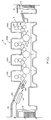
- the method of the present invention may be practiced in connection with multiple printing units of a sheet-fed, rotary offset printing press 12.
- the press 12 is a four color, rotary offset printing press which is capable of handling individual printed sheets having a width of approximately 40" (102 centimeters) and capable of printing 10,000 sheets or more per hour, such as that manufactured by Heidelberg Druckmaschinen AG of Germany under its designation Heidelberg Speedmaster 102V.
- the press 12 includes a press frame 14 coupled on the right end to a sheet feeder 16 from which sheets, herein designated S, are individually and sequentially fed into the press, and at the opposite end to a delivery sheet stacker 18 in which the freshly printed sheets are collected and uniformly stacked. Interposed between the sheet feeder 16 and the delivery sheet stacker 18 are four substantially identical sheet printing units 20A, 20B, 20C and 20D which are capable of printing different color inks onto the sheets as they are transferred through the press.
- each printing unit includes a plate cylinder 22, a blanket cylinder 24, an impression cylinder 26 and an inking transfer apparatus 36.
- a dampening system is not illustrated, since it is not needed in practice of the present invention.
- Freshly printed sheets S from the impression cylinder 26 are transferred to the next printing unit by transfer cylinders T1, T2, T3.
- a protective and/or decorative coating is applied to the printed sheets by a coating unit 28 which is positioned adjacent to the last printing unit 20D.
- the freshly printed and/or coated sheets S are delivered to the sheet stacker 18 by a delivery conveyor system, generally designated 30.
- the delivery conveyor 30 is of conventional design and includes a pair of endless delivery gripper chains 32 carrying laterally disposed gripper bars having gripper elements for gripping the leading edge of a freshly printed sheet S as it leaves the impression cylinder 26. As the leading edge of the printed sheet S is gripped by the gripper elements, the delivery chains 32 pull the gripper bars and sheet S away from the last impression cylinder 26 and deliver the freshly printed and/or coated sheet to the sheet stacker 18.
- the freshly printed and/or coated sheets S pass through the exposure zone of a delivery dryer assembly 34 which includes an infra-red thermal radiation, high velocity hot air flow and a high performance heat and moisture extractor for drying.the aqueous ink and/or the protective/decorative coating.
- each printing unit includes an inking apparatus 36 having a train of inking rollers 38 arranged to transfer aqueous ink Q from an ink fountain 40 to the plate cylinder 22. This is accomplished with the aid of a fountain roller 42 and a ductor roller 44.
- the fountain roller 42 projects into the fountain 40, whereupon its surface is wetted with aqueous ink.
- the aqueous printing ink Q is transferred intermittently to the ink roller train 38 by the ductor roller 44.
- the inking roller train 38 supplies aqueous ink Q to the image areas of a waterless printing plate 46.
- a waterless printing plate 46 having oleophilic image and oleophobic non-image surface areas may be obtained from Toray Industries, Inc. of New York, U.S.A. and Urayasu, Chiba, Japan.
- the aqueous printing ink Q is transferred from the waterless printing plate 46 to an ink receptive blanket 47 which is mounted on the blanket cylinder 24.
- the aqueous printing ink is transferred from the image surface areas of the waterless printing plate 46 to the ink receptive surface of the blanket 47.
- the inked image carried on the blanket 47 is transferred to a substrate S as the substrate is transferred through the nip 49 between the impression cylinder 26 and the blanket 47.
- the waterless printing plate 46 is mounted on the plate cylinder 22 by a mechanical clamp 48.
- the waterless printing plate 46 has a trailing edge portion 46B which is secured to the plate cylinder 22 by the mechanical clamp 48.
- the leading edge 46A of the waterless printing plate is secured within an elongated slot of a ratchet wheel R. After the waterless printing plate 46 has been mounted in place, the ratchet wheel R is tightened to secure the printing plate 46 in tension about the plate cylinder 22.
- the waterless printing plate 46 includes a thin aluminum layer 50 which is bonded to a polyester film base 52.
- the external surface of the aluminum sheet 50 is covered by a layer 54 of silicon dioxide (SiO2).
- the silicon dioxide layer 54 is etched to expose the surface 50A of the underlying aluminum layer 50, thereby defining a reservoir cell C for receiving a predetermined amount of the aqueous printing ink.
- the aluminum surface layer 50A is hydrophilic, and is thus wettable by the aqueous printing ink.
- the silicon dioxide film or coating 54 is hydrophobic, and thus repels the aqueous printing ink.
- the exposed surface 50A of the underlying aluminum layer 50 defines an image surface area
- the external surface 54A of the silicon dioxide layer 54 defines a non-image surface area of the waterless printing plate.
- the underlying hydrophilic image areas 50A are recessed with respect to the hydrophobic, non-image surface areas 54A.
- the hydrophobic, non-image material 54 forms a sidewall boundary of each reservoir cell C, thus providing clean separation and sharp release of a precise amount of aqueous ink Q.
- a predetermined volume of aqueous printing ink is retained in the cell C by adhesion wetting of the image surface area until contacted by the ink receptive blanket. Since there is no affinity for the aqueous printing ink with respect to the surrounding sidewalls of the cell C, clean release of the aqueous printing ink from each reservoir cell C is accomplished, so that each dot is sharply printed and well-defined.
- the freshly printed ink on the sheet S is dried before the sheet S reaches the next printing unit.
- a primary high velocity hot air dryer and a high performance heat and moisture extractor 56 is mounted adjacent the impression cylinder 26, and directs high velocity hot air flow into an exposure zone Z and onto the printed sheet. Simultaneously, hot moist air and volatiles are extracted from the exposure zone Z while the printed sheet is in contact with the impression cylinder. Because the aqueous component of the ink dries by evaporation, the aqueous ink on the freshly printed sheet S is dry before the sheet reaches the next printing unit 20B.
- an additional dryer/extractor unit may be used to ensure thorough drying of the aqueous ink on the freshly printed sheet.
- an additional high velocity hot air dryer/extractor unit 58 is installed in an interstation position adjacent the intermediate transfer cylinder T2, and directs high velocity hot air flow through an exposure zone Z onto the freshly printed sheet S before it is printed in the next printing unit.
- the high velocity, hot air dryer and high performance heat and moisture extractor units 56, 58 utilize high velocity air jets which scrub and break-up the moist air layer which clings to the surface of each freshly printed sheet S.
- high velocity air is heated to a high temperature as it flows along a resistance heating element within an air delivery baffle tube.
- High velocity jets J of hot air are discharged through multiple airflow apertures onto the freshly printed side of the sheet S as it moves through the dryer exposure zone Z.
- Each dryer assembly includes a pair of air delivery dryer heads 56A, 56B and 58A, 58B, respectively, which are arranged in spaced, side-by-side relation.
- Each extractor includes a manifold coupled to the dryer heads and draws the moisture vapor and high velocity hot air as indicated by the arrow A from the exposure zone Z through a longitudinal air gap 59 between the dryer heads. According to this arrangement, each printed sheet S is dried before it is run through the next printing unit.
- Aqueous printing inks which are suitable for use in the practice of the present invention include those which traditionally have been used in flexographic (relief) printing, letter press printing and rotogravure printing. Such aqueous inks contain colored pigments and/or soluble dyes, binders which fix the pigments onto the surface of the printed substrate, and waxes, defoamers and thickeners. Aqueous printing inks predominantly contain water as a solvent, diluent and/or vehicle.
- the thickeners which are preferred include alginates, starch, cellulose and its derivatives, for example cellulose esters or cellulose ethers and the like. Coloring agents including organic as well as inorganic pigments may be derived from dyes which are insoluble in water.
- the aqueous printing ink used in the practice of this invention has a dynamic viscosity of 2,000 to 4,000 centipoise, measured at 73°F (23°C) by means of a viscometer.
- the aqueous printing ink has a gel-like consistency at 73°F (23°C).
- the solvent of the printing ink composition may be predominantly glycol or the like, and may contain a minor water component, with the pigment being bound by an appropriate resin.
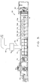
- the method of the present invention may be practiced in combination with a web-fed rotary offset press 60.
- the web press 60 is a five color, rotary web offset, perfecting printing press which is capable of handling a continuous web having a width of approximately 38 inches (97 centimeters) and capable of running at 500 feet or more per minute, such as that manufactured by Heidelberg Druckmaschinen AG of Germany under its designation "Heidelberg Web”.
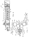
- the web press 60 includes a press frame 62 coupled on its right end to a web supply unit 64 from which a web substrate, herein designated W, is continuously fed into the web press, and at the opposite end, to a sheet folding unit 66 and a sheet cutter/stacker 68. Interposed between the web supply unit 64 and the folding unit 66 are four substantially identical web printing units 70A, 70B, 70C and 70D, which are capable of printing different color inks onto the web W as it passes through the press, and a fifth unit 70E which is capable of optionally applying a fifth color or a protective and/or decorative coating to the freshly printed substrate.
- the press may include as many as eight to ten printing units, each of which prints blanket-to-blanket. According to this arrangement, the printing is performed in the perfecting mode so that both sides of the web substrate are printed and/or coated as it passes through the web press 60.
- the freshly printed oil-based ink is dried as the web W passes through an oven 72.
- the oven is operated at a temperature of approximately 300°F (149°C) so that high boiling range mineral oils and other volatile solvents will be removed, and drying occurs substantially as a solvent evaporation process.
- the web substrate W then passes through a chill roller stand 74 having multiple chill rollers for reducing the high temperature of the web substrate W and ink, which causes the ink to set and harden.
- the web press 60 has been modified by the removal of the oven 72 and the associated catalytic converter afterburner equipment 76, 78, 82, and the chill roller stand 74.
- the oven 72, catalytic converter 76 and chill roller stand 74 and oil-based inks are not needed in the practice of the present invention. Instead, water-based inks are used and toxic distillates are eliminated. Consequently, the distillate disposal problem and the large capital investment connected with a high BTU oven system, chill roller unit and after-burner are also eliminated. Elimination of the large capital investment equipment is made possible by utilizing an aqueous ink system and waterless printing plates in combination with the high velocity, hot air dryer heat and moisture extractor units of the present invention.
- the web press 60 has been simplified considerably by removal of the oven 72, the associated catalytic converter afterburner equipment 76, 78, 82 and the chill roller stand 74.
- the web press 60 is further modified by the installation of waterless printing plates 46A, 46B on the plate cylinders 22A, 22B, respectively.
- the waterless printing plates 46A, 46B are engaged against lower and upper blankets 47A, 47B, respectively, which prints both sides of the web substrate W.
- Each web printing unit includes inking apparatus 36 having a train of inking rollers 38 arranged to transfer aqueous ink Q from an ink fountain 40 to the waterless printing plates 46A, 46B, respectively.
- the transfer of aqueous ink Q is accomplished with the aid of a fountain roller 42 and a ductor roller 44.
- the fountain roller 42 projects into the fountain 40, whereupon its surface is wetted with the aqueous ink Q.
- the inking roller train 38 supplies aqueous ink to the image areas of the waterless printing plates 46A, 46B, respectively.
- the waterless printing plate, blanket-to-blanket printing arrangement is repeated in each printing unit 70A, 70B, 70C, 70D and 70E.
- the last printing unit 70E may be utilized for applying a decorative/protective coating, or it may be configured as shown in FIGURE 7 to print a fifth color.
- each dryer/extractor unit 84, 86 includes a pair of dryer heads 84A, 84B and 86A, 86B, respectively.
- Heated air jets J are discharged at high velocity through precision holes located in the dryer heads onto the freshly printed web W as it moves from one printing unit to the next printing unit.
- the boundary layer of air which follows the web W is displaced from the surface of the web W by the high velocity hot air jets J.
- the aqueous ink Q is completely dried as a result of evaporation in response to the absorption of thermal energy, and as a result of hot air convection/extraction.
- Each extractor includes a manifold which is coupled to the dryer heads and draws moisture-laden hot air A from the exposure zones Z on both sides of the web W through a longitudinal air gap 59 between the dryer heads. According to this arrangement, the aqueous ink Q is completely dried before the web substrate is pulled to the next printing unit.
- the method of the present invention eliminates the use of toxic distillates of oil-based printing inks, so that the distillate disposal problem and the large capital investment connected with an oven system, chill roller stand and after burner are eliminated.
- the oven itself represents a substantial capital investment, in addition to the high volume of fuel which it consumes, together with the afterburner or catalytic converter which eliminates the distillate vapors before the gases are exhausted into the atmosphere.
- the chill roller stand 74 also represents a substantial capital investment and is needed in the conventional heat-set, web offset press to reduce the high temperature of the web substrate W and thus preventing smearing of the ink as the web substrate is further handled and processed in the folding unit 66 and cutting/stacker unit 68.
- a further disadvantage of the high temperature oven 72 in addition to its expense and space requirements, is that the oven can take out too much moisture from the web substrate W during the drying process, which will create significant static electricity problems and cause the substrate to become brittle during folding.
- Moisture control and electrostatic control systems are not needed in the practice of the present invention since the drying of the substrate is carried out between printing units by the interstation high velocity hot air dryer and heat and moisture extractor units 56, 58 (sheet-fed press), the interstation high velocity, hot air dryer and heat and moisture extractor units 84, 86 (web press).
- the water-based inks as used in the web press embodiment of the present invention dry at a relatively moderate drying temperature provided by the interstation high velocity hot air dryer of the present invention. Because the freshly printed web W is dried between each printing unit, clarity and print quality are substantially improved since the aqueous ink Q is dried at each printing unit (dry trap) before the web substrate W enters the next printing unit. Because the web substrate is dry before it enters the next printing unit, unit-to-unit dot gain and backtrapping on the blanket are completely eliminated. Consequently, by utilizing the method of the present invention, the oven 72, the chill roller stand 74, the dampening units and the afterburner 76 are eliminated. A substantial capital saving as well as a savings of floor space are thus realized along with a substantial improvement in printing quality.
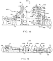
- the invention may be practiced in combination with an open web press 90 as shown in FIGURE 8 which is equipped with waterless printing plates 46A, 46B, using aqueous ink Q and inter-station dryers/extractor units 84, 86.
- Open web presses are commonly used as newspaper presses and have significant down-time or idle time between runs.
- the newspaper press 90 can be utilized for printing on higher quality paper, for example coated stock, super-calendered stock and the like.
- the newspaper press 90 that may be used only one day a week for producing a weekly newspaper, can be used for the remainder of the week for custom printing jobs that require a better grade of paper, for example advertising brochures, catalogs, direct mail pieces, glossy newspaper inserts and the like.
- the operation of the open web newspaper press 90 of FIGURE 8 is substantially the same as the operation of the rotary offset, web fed perfecting press of FIGURE 5, except that multiple printing units 92A, 92B, 92C and 92D are arranged in a vertical array for printing four colors on a first web W1.
- a fifth printing unit is separated from the vertical array and prints a fifth color, usually black, on a second web W2.
- the first web W1 is pulled from a supply roll 94 in an unwind stand 96. After the first web W1 is printed in the open web vertical array, it is fed into an assembly unit 98 where the web is folded and cut. The freshly printed web W2 is likewise fed from a supply roll through the printing unit 92E into the assembly station 98, where it is folded, cut, interleaved and assembled together with folded sections of the multicolor web W1.
- a coater unit may be added for providing a spot or blanket coating, for either protective or decorative purposes.
- an open web newspaper press 90 which previously had been utilized only for printing newspapers, telephone directories and the like on very absorbent stock, may now be used for printing on high quality, low absorbency paper for completing specialty printing jobs during when the press is not being used for newspaper production.
- the inventive may also be practiced on a rotary offset, non-perfecting web press 100 as shown in FIGURE 9.
- the web press 100 includes multiple printing units 102A, 102B, 102C, and 102D, and is typically used for printing business forms on uncoated stock.
- the rotary offset web press 100 may be used for printing on coated stock, for example catalogs, magazines, brochures and glossy newspaper inserts.
- the web offset press 100 prints on only one side of the web W in an arrangement referred to as non-perfecting "blanket-to-steel". That is, the inked image is transferred from a blanket 47 through a nip between a blanket 47 and an impression cylinder 26, so that printing is accomplished on one side only.
- the press 100 Perfecting (printing on both sides) is accomplished in the press 100 by routing the web W through interstation turn bars and printing on the opposite side.
- the marking and smearing problems are eliminated by drying the aqueous ink on the web at each printing unit.
- This permits the web press 100 to overprint coated paper, and also permits the use of a better grade of paper.
- the web press 100 which traditionally is dedicated for printing uncoated paper business forms, may be easily converted for print jobs which require a better quality paper and/or a glossy finish.
- the rotary offset printing method of the present invention eliminates the problems associated with the two-component water/oil chemistry of offset lithography, because a liquid dampening solution is not used, and the aqueous printing ink does not contain oily components.
- the aqueous component of the water-based ink is dried by evaporation, using a combination of high velocity hot air drying and high performance heat and moisture extraction, so that the freshly printed ink is dried on the substrate before it reaches the next printing unit. Since a liquid dampening solution is not used, there is no color dilution. Because oily ink components are not used, backtrapping on the blanket is eliminated.
- the aqueous ink is completely dry as the substrate enters the next printing unit, and unit-to-unit dot gain is also eliminated. Because of the large surface energy differential of the hydrophobic non-image areas of the waterless printing plate relative to the aqueous printing ink, there is clean separation and release of the aqueous ink from the non-image surface areas. Consequently, a crisper image, more faithful color reproduction and high color intensity are obtained.
- the control of color intensity is improved by the waterless printing plate in which the hydrophilic image surface areas are recessed with respect to the hydrophobic, non-image surface areas.
- the hydrophobic, non-image material forms the sidewall boundary of each image or dot area, thus providing clean separation and release of a precise amount of aqueous ink. Since oily ink components such as high-boiling range mineral oil are not used, harmful volatiles are not released into the atmosphere. Because the aqueous printing inks are stable and relatively insensitive to temperature change, it is not necessary to control the temperature of the inking rollers, the plate cylinder or other parts of the press.
- the high velocity, hot air dryer and high performance heat and moisture extractor cleans the substrate sheet or web between printing units. That is, the high velocity hot air and moisture extractor also suctions off loose paper dust, fibers and any foreign particulate material which may be on the substrate. Such debris will be removed and extracted from the substrate prior to entering the next printing unit. The removal of such particulate material from the sheet or web helps maintain printing quality and keeps the printing plate and the blanket in a clean condition, thus reducing press down-time which would otherwise be required for washing and/or replacing the blanket and/or printing plate.
- dampening system Because a dampening system is not needed, it may be disconnected and/or removed if it is already on the press, and need not be installed. The space which otherwise would be occupied by the dampening system thus becomes available for other purposes. Except for the initial installation of the dryer/extractor units, and the substitution of a waterless printing plate and using aqueous ink, no press modification is required.
Landscapes
- Engineering & Computer Science (AREA)
- Mechanical Engineering (AREA)
- Printing Methods (AREA)
- Supply, Installation And Extraction Of Printed Sheets Or Plates (AREA)
- Rotary Presses (AREA)
Applications Claiming Priority (2)
| Application Number | Priority Date | Filing Date | Title |
|---|---|---|---|
| US291024 | 1988-12-28 | ||
| US29102494A | 1994-08-16 | 1994-08-16 |
Publications (1)
| Publication Number | Publication Date |
|---|---|
| EP0697290A1 true EP0697290A1 (fr) | 1996-02-21 |
Family
ID=23118510
Family Applications (1)
| Application Number | Title | Priority Date | Filing Date |
|---|---|---|---|
| EP95305671A Withdrawn EP0697290A1 (fr) | 1994-08-16 | 1995-08-15 | Presse offset à plusieurs couleurs utilisant d'encre aqueuse et plaques d'impression à sec avec stations intermédiaires de séchage et d'extraction |
Country Status (3)
| Country | Link |
|---|---|
| EP (1) | EP0697290A1 (fr) |
| JP (1) | JPH08169188A (fr) |
| CA (1) | CA2156005A1 (fr) |
Cited By (8)
| Publication number | Priority date | Publication date | Assignee | Title |
|---|---|---|---|---|
| DE10065481A1 (de) * | 1999-12-28 | 2001-09-20 | Hitachi Ltd | Druckplatte und Druckmaschine, in der die Druckplatte verwendet ist |
| US6505023B2 (en) | 1999-09-21 | 2003-01-07 | Minolta Co., Ltd. | Color image forming apparatus and method |
| EP1600290A1 (fr) * | 2001-11-22 | 2005-11-30 | Koenig & Bauer Aktiengesellschaft | Utilisation d'une encre d'imprimerie dans une unité d'impression et unité d'impression d'une presse rotative |
| WO2008015152A3 (fr) * | 2006-07-31 | 2008-07-17 | Koenig & Bauer Ag | Unité d'impression d'une imprimante rotative à bobines |
| EP2927010A4 (fr) * | 2012-11-28 | 2017-02-01 | Yamato Grand Co., Ltd. | Procédé d'impression utilisant une imprimante offset |
| WO2017134114A1 (fr) * | 2016-02-01 | 2017-08-10 | Windmöller & Hölscher Kg | Dispositif et procédé de séchage d'une matière en bande d'une machine d'impression |
| CN111231495A (zh) * | 2020-03-19 | 2020-06-05 | 重庆宏劲印务有限责任公司 | 卷筒纸柔性版uv油墨无水胶印的实现方法及其胶印机 |
| CN111674150A (zh) * | 2020-07-19 | 2020-09-18 | 苏州郎旭志远科技有限公司 | 一种环保型包装袋印刷设备及其印刷工艺 |
Families Citing this family (6)
| Publication number | Priority date | Publication date | Assignee | Title |
|---|---|---|---|---|
| US6877247B1 (en) * | 2000-08-25 | 2005-04-12 | Demoore Howard W. | Power saving automatic zoned dryer apparatus and method |
| US6709503B1 (en) | 2002-12-19 | 2004-03-23 | Sun Chemical Corporation | Waterbased heatset offset ink compositions |
| JP2007098616A (ja) * | 2005-09-30 | 2007-04-19 | Mitsubishi Heavy Ind Ltd | 印刷機械 |
| US20100064917A1 (en) * | 2006-11-24 | 2010-03-18 | Goss International Montataire Sa | Printing machine and corresponding method |
| JP2016083791A (ja) * | 2014-10-23 | 2016-05-19 | Dicグラフィックス株式会社 | 水性インキ組成物および水性ワニス組成物を用いた印刷方法及びその方法によって得られる印刷物 |
| JP6688510B2 (ja) * | 2015-06-03 | 2020-04-28 | アイマー・プランニング株式会社 | 印刷機の湿水装置およびこれを備えた印刷機 |
Citations (4)
| Publication number | Priority date | Publication date | Assignee | Title |
|---|---|---|---|---|
| GB2003427A (en) * | 1977-09-05 | 1979-03-14 | Polygraph Leipzig Kom Veb | Rotary sheet printing machine |
| EP0076905A2 (fr) * | 1981-10-10 | 1983-04-20 | BASF Lacke + Farben AG | Procédé d'impression à plat |
| US5086700A (en) * | 1990-09-10 | 1992-02-11 | Eduard Van Den Berg | Drying/curing apparatus for printing presses |
| EP0647524A1 (fr) * | 1993-10-06 | 1995-04-12 | DeMoore, Howard W. | Dispositif sécheur à air chaud à haute vitesse et dispositif d'extraction |
-
1995
- 1995-08-14 CA CA 2156005 patent/CA2156005A1/fr not_active Abandoned
- 1995-08-15 EP EP95305671A patent/EP0697290A1/fr not_active Withdrawn
- 1995-08-16 JP JP24354195A patent/JPH08169188A/ja active Pending
Patent Citations (4)
| Publication number | Priority date | Publication date | Assignee | Title |
|---|---|---|---|---|
| GB2003427A (en) * | 1977-09-05 | 1979-03-14 | Polygraph Leipzig Kom Veb | Rotary sheet printing machine |
| EP0076905A2 (fr) * | 1981-10-10 | 1983-04-20 | BASF Lacke + Farben AG | Procédé d'impression à plat |
| US5086700A (en) * | 1990-09-10 | 1992-02-11 | Eduard Van Den Berg | Drying/curing apparatus for printing presses |
| EP0647524A1 (fr) * | 1993-10-06 | 1995-04-12 | DeMoore, Howard W. | Dispositif sécheur à air chaud à haute vitesse et dispositif d'extraction |
Cited By (17)
| Publication number | Priority date | Publication date | Assignee | Title |
|---|---|---|---|---|
| US6505023B2 (en) | 1999-09-21 | 2003-01-07 | Minolta Co., Ltd. | Color image forming apparatus and method |
| DE10065481B4 (de) * | 1999-12-28 | 2006-09-07 | Ricoh Printing Systems, Ltd. | Druckverfahren, Druckplatte und Druckmaschine, in der die Druckplatte verwendet ist |
| DE10065481A1 (de) * | 1999-12-28 | 2001-09-20 | Hitachi Ltd | Druckplatte und Druckmaschine, in der die Druckplatte verwendet ist |
| EP1815984A3 (fr) * | 2001-11-22 | 2011-04-27 | Koenig & Bauer AG | Procédé d'utilisation d'un imprimé d'une presse rotative |
| EP1600290A1 (fr) * | 2001-11-22 | 2005-11-30 | Koenig & Bauer Aktiengesellschaft | Utilisation d'une encre d'imprimerie dans une unité d'impression et unité d'impression d'une presse rotative |
| EP1681160A1 (fr) * | 2001-11-22 | 2006-07-19 | Koenig & Bauer Aktiengesellschaft | Procédé de fonctionnement d'un mécanisme d'impression |
| EP1681162A3 (fr) * | 2001-11-22 | 2006-08-02 | Koenig & Bauer Aktiengesellschaft | Machine d'impression avec unités d'impression |
| US7089855B2 (en) | 2001-11-22 | 2006-08-15 | Koenig & Bauer Aktiengesellschaft | Utilization of a printing ink in a printing group and printing group of a rotary printing press |
| US7261034B2 (en) | 2001-11-22 | 2007-08-28 | Koenig & Bauer Aktiengesellschaft | Utilization of a printing ink in a printing group and printing group of a rotary printing press |
| US7409910B2 (en) | 2001-11-22 | 2008-08-12 | Koenig & Bauer Aktiengesellschaft | Utilization of a printing ink in a printing group and printing group of a rotary printing press |
| WO2008015152A3 (fr) * | 2006-07-31 | 2008-07-17 | Koenig & Bauer Ag | Unité d'impression d'une imprimante rotative à bobines |
| CN101495314B (zh) * | 2006-07-31 | 2011-04-20 | 柯尼格及包尔公开股份有限公司 | 具有至少一个卷筒纸轮转印刷机的印刷装置的印刷单元 |
| EP2927010A4 (fr) * | 2012-11-28 | 2017-02-01 | Yamato Grand Co., Ltd. | Procédé d'impression utilisant une imprimante offset |
| WO2017134114A1 (fr) * | 2016-02-01 | 2017-08-10 | Windmöller & Hölscher Kg | Dispositif et procédé de séchage d'une matière en bande d'une machine d'impression |
| CN111231495A (zh) * | 2020-03-19 | 2020-06-05 | 重庆宏劲印务有限责任公司 | 卷筒纸柔性版uv油墨无水胶印的实现方法及其胶印机 |
| CN111674150A (zh) * | 2020-07-19 | 2020-09-18 | 苏州郎旭志远科技有限公司 | 一种环保型包装袋印刷设备及其印刷工艺 |
| CN111674150B (zh) * | 2020-07-19 | 2021-03-09 | 湖南鹤祥包装有限公司 | 一种环保型包装袋印刷设备及其印刷工艺 |
Also Published As
| Publication number | Publication date |
|---|---|
| JPH08169188A (ja) | 1996-07-02 |
| CA2156005A1 (fr) | 1996-02-17 |
Similar Documents
| Publication | Publication Date | Title |
|---|---|---|
| US6435086B1 (en) | Retractable inking/coating apparatus having ferris movement between printing units | |
| US5651316A (en) | Retractable printing/coating unit operable on the plate and blanket cylinders simultaneously from the dampener side of the first printing unit or any consecutive printing unit of any rotary offset printing press | |
| USRE41048E1 (en) | Combined Lithographic/flexographic printing apparatus and process | |
| US6443058B1 (en) | Combined printing method and hybrid printing machine | |
| US8402891B2 (en) | Methods for printing a print medium, on a web, or a printed sheet output | |
| CA2156005A1 (fr) | Presse offset a plusieurs couleurs, faisant usage d'encre aqueuse et de planches d'impression sans eau, et avec sechage et extraction entre les stations | |
| US4939992A (en) | Flexographic coating and/or printing method and apparatus including interstation driers | |
| US4841903A (en) | Coating and printing apparatus including an interstation dryer | |
| US5960713A (en) | Retractable printing-coating unit operable on the plate and blanket cylinders simultaneously from the dampener side of the first printing unit or any consecutive printing unit or any rotary offset printing press | |
| US5598777A (en) | Retractable printing/coating unit operable on the plate and blanket cylinders | |
| US4815379A (en) | Sheet transfer cylinder between printing units of a rotary printing machine | |
| DK157439B (da) | Fremgangsmaade til fladtryk | |
| US20020178944A1 (en) | Lightweight portable compact universal printer coater adaptable to printing units on the same press or other presses of the same nominal printing width | |
| EP0767058A2 (fr) | Machine à imprimer | |
| EP1202863B1 (fr) | Dispositif de guidage courbe pour machine a imprimer | |
| US20030172824A1 (en) | Short inking system for a rotary printing machine | |
| CN101495314B (zh) | 具有至少一个卷筒纸轮转印刷机的印刷装置的印刷单元 | |
| JPH10226148A (ja) | 非吸収性の物質を多色印刷する方法 | |
| EP0389252A2 (fr) | Procédé d'impression | |
| US20070272104A1 (en) | Coating device | |
| US20040074409A1 (en) | Coating device for a rotary printing machine | |
| US7004069B2 (en) | Apparatus for a stable machine run on printing units of a rotary press for operation with part-width printing material | |
| JPH07205391A (ja) | オフセット輪転印刷機の印刷機構 | |
| US7000542B2 (en) | Low cost litho printing press, printing plate, and method for printing paste-type oil-based litho ink which eliminate the dampener and dampening solution therefrom | |
| WO2007106433A2 (fr) | Presse a imprimer satellite a bobines doubles |
Legal Events
| Date | Code | Title | Description |
|---|---|---|---|
| PUAI | Public reference made under article 153(3) epc to a published international application that has entered the european phase |
Free format text: ORIGINAL CODE: 0009012 |
|
| AK | Designated contracting states |
Kind code of ref document: A1 Designated state(s): AT BE CH DE DK ES FR GB GR IE IT LI LU MC NL PT SE |
|
| 17P | Request for examination filed |
Effective date: 19960819 |
|
| 17Q | First examination report despatched |
Effective date: 19970730 |
|
| STAA | Information on the status of an ep patent application or granted ep patent |
Free format text: STATUS: THE APPLICATION IS DEEMED TO BE WITHDRAWN |
|
| 18D | Application deemed to be withdrawn |
Effective date: 19980217 |