EP0697307B1 - Dispositif de verrouillage pour dossiers divisible et escamotable dans un siège arrière pour véhicules automobiles - Google Patents
Dispositif de verrouillage pour dossiers divisible et escamotable dans un siège arrière pour véhicules automobiles Download PDFInfo
- Publication number
- EP0697307B1 EP0697307B1 EP95106842A EP95106842A EP0697307B1 EP 0697307 B1 EP0697307 B1 EP 0697307B1 EP 95106842 A EP95106842 A EP 95106842A EP 95106842 A EP95106842 A EP 95106842A EP 0697307 B1 EP0697307 B1 EP 0697307B1
- Authority
- EP
- European Patent Office
- Prior art keywords
- locking
- bolt
- backrest
- additional
- sensor
- Prior art date
- Legal status (The legal status is an assumption and is not a legal conclusion. Google has not performed a legal analysis and makes no representation as to the accuracy of the status listed.)
- Expired - Lifetime
Links
- 230000001133 acceleration Effects 0.000 claims description 11
- 230000001960 triggered effect Effects 0.000 claims description 5
- 230000000903 blocking effect Effects 0.000 description 2
- 230000006835 compression Effects 0.000 description 2
- 238000007906 compression Methods 0.000 description 2
- 239000006071 cream Substances 0.000 description 1
Images


Classifications
-
- B—PERFORMING OPERATIONS; TRANSPORTING
- B60—VEHICLES IN GENERAL
- B60N—SEATS SPECIALLY ADAPTED FOR VEHICLES; VEHICLE PASSENGER ACCOMMODATION NOT OTHERWISE PROVIDED FOR
- B60N2/00—Seats specially adapted for vehicles; Arrangement or mounting of seats in vehicles
- B60N2/24—Seats specially adapted for vehicles; Arrangement or mounting of seats in vehicles for particular purposes or particular vehicles
- B60N2/42—Seats specially adapted for vehicles; Arrangement or mounting of seats in vehicles for particular purposes or particular vehicles the seat constructed to protect the occupant from the effect of abnormal g-forces, e.g. crash or safety seats
- B60N2/433—Safety locks for back-rests, e.g. with locking bars activated by inertia
-
- B—PERFORMING OPERATIONS; TRANSPORTING
- B60—VEHICLES IN GENERAL
- B60N—SEATS SPECIALLY ADAPTED FOR VEHICLES; VEHICLE PASSENGER ACCOMMODATION NOT OTHERWISE PROVIDED FOR
- B60N2/00—Seats specially adapted for vehicles; Arrangement or mounting of seats in vehicles
- B60N2/24—Seats specially adapted for vehicles; Arrangement or mounting of seats in vehicles for particular purposes or particular vehicles
- B60N2/32—Seats specially adapted for vehicles; Arrangement or mounting of seats in vehicles for particular purposes or particular vehicles convertible for other use
- B60N2/36—Seats specially adapted for vehicles; Arrangement or mounting of seats in vehicles for particular purposes or particular vehicles convertible for other use into a loading platform
- B60N2/366—Seats specially adapted for vehicles; Arrangement or mounting of seats in vehicles for particular purposes or particular vehicles convertible for other use into a loading platform characterised by the locking device
-
- B—PERFORMING OPERATIONS; TRANSPORTING
- B60—VEHICLES IN GENERAL
- B60N—SEATS SPECIALLY ADAPTED FOR VEHICLES; VEHICLE PASSENGER ACCOMMODATION NOT OTHERWISE PROVIDED FOR
- B60N2/00—Seats specially adapted for vehicles; Arrangement or mounting of seats in vehicles
- B60N2/68—Seat frames
-
- B—PERFORMING OPERATIONS; TRANSPORTING
- B60—VEHICLES IN GENERAL
- B60N—SEATS SPECIALLY ADAPTED FOR VEHICLES; VEHICLE PASSENGER ACCOMMODATION NOT OTHERWISE PROVIDED FOR
- B60N2/00—Seats specially adapted for vehicles; Arrangement or mounting of seats in vehicles
- B60N2/68—Seat frames
- B60N2/686—Panel like structures
-
- B—PERFORMING OPERATIONS; TRANSPORTING
- B60—VEHICLES IN GENERAL
- B60R—VEHICLES, VEHICLE FITTINGS, OR VEHICLE PARTS, NOT OTHERWISE PROVIDED FOR
- B60R21/00—Arrangements or fittings on vehicles for protecting or preventing injuries to occupants or pedestrians in case of accidents or other traffic risks
- B60R21/02—Occupant safety arrangements or fittings, e.g. crash pads
- B60R21/026—Rigid partitions inside vehicles, e.g. between passengers and load compartments
-
- B—PERFORMING OPERATIONS; TRANSPORTING
- B60—VEHICLES IN GENERAL
- B60N—SEATS SPECIALLY ADAPTED FOR VEHICLES; VEHICLE PASSENGER ACCOMMODATION NOT OTHERWISE PROVIDED FOR
- B60N2205/00—General mechanical or structural details
- B60N2205/30—Seat or seat parts characterised by comprising plural parts or pieces
- B60N2205/35—Seat, bench or back-rests being split laterally in two or more parts
-
- B—PERFORMING OPERATIONS; TRANSPORTING
- B60—VEHICLES IN GENERAL
- B60R—VEHICLES, VEHICLE FITTINGS, OR VEHICLE PARTS, NOT OTHERWISE PROVIDED FOR
- B60R21/00—Arrangements or fittings on vehicles for protecting or preventing injuries to occupants or pedestrians in case of accidents or other traffic risks
- B60R21/02—Occupant safety arrangements or fittings, e.g. crash pads
- B60R2021/0273—Occupant safety arrangements or fittings, e.g. crash pads automatically movable to an operative position, e.g. in case of collision or impending collision
Definitions
- the invention relates to a device for locking of split folding backrests on the rear seats of motor vehicles according to the preamble of claim 1.
- a device of this type is described in DE-A-3 026 259 (A1) described.
- this known device for Locking a backrest that can be folded forward locking lever connected to the backrest is provided, which is in the upright position of the backrest engages behind a body-side locking device.
- unlocking the Avoiding the backrest points to the body side Latching device on a linearly displaceable mass that comes into a position under the influence of inertial forces, in which the locking lever is additionally locked becomes.
- the locking lever is additionally locked becomes.
- Another lock for a backrest is out DE-A-3 211 363 (A1).
- This lock is for split rear seat backrests provided and has an additional locking device in the Dividing gap arranged between the two backrest halves and for releasable locking of these backrest halves is provided against each other.
- This locking device but is for joint operation with a common, Locking lock arranged on one side of the backrest half or element formed.
- the object of the invention is such a device to create that in the event of an impact or strong Braking the backrest parts in an upright position (Sitting position) holds and so an improved protection in front of objects placed behind the rear seats, which are accelerated in such a case becomes.
- the sensor can be set to a certain threshold be set to respond. This can be the inertia a crowd can be exploited to provide additional locking trigger directly.
- the sensor can also be an energy store, e.g. activate a gas generator, who uses the generated gas to actuate a pulling or pushing mechanism, which brings the additional locking in the locking or holding position or the gas is fed into an actuating cylinder in which one with the additional lock connected working piston is moved.
- an energy store e.g. activate a gas generator, who uses the generated gas to actuate a pulling or pushing mechanism, which brings the additional locking in the locking or holding position or the gas is fed into an actuating cylinder in which one with the additional lock connected working piston is moved.
- the additional lock can preferably be arranged in the upper region of the backrest be to increase the forces holding the backrest parts.
- Slidable bolts of the additional locking can be positive and / or non-positive intervene in appropriately trained recordings.
- a or several locking bolts can be used, which are triggered by the sensor in the direction of the adjacent backrest part in one of the locking pin shape appropriately trained recording of the adjacent backrest part is moved.
- the bolt or bolts can act as an active locking bolt. In the event of a crash, this creates a bond between the divided backrest parts reached.
- a compression spring e.g. Helical compression spring.
- the respective backrest part can also preferably be in the upper backrest area a pull rope can be attached, which can be tensioned with the help of a gas generator.
- a pull rope can be attached, which can be tensioned with the help of a gas generator.
- the tension of the pull ropes is like this interpret that if necessary, the respective backrest part additionally with the Pull rope is held.
- the gas generator can in this case on the floor of the trunk be attached behind the rear seats.
- he can in the Pull mechanism for the pull rope (s) can be integrated.
- It can also be connected to a gas generator bolt after triggering the Gas generator in receptacles designed according to the shape of the bolt intervene and lock the backrest parts in the sitting position. It can either the gas generator or the latch can be attached to the backrest part or intervene in an existing recording there and the other part on Be fixed to the vehicle chassis or engage there in a receptacle.
- At least one position or position sensor on the backrest parts be arranged, which prevents the additional locking from being triggered if one of the two adjacent backrest parts is not folded up Position, i.e. in sitting position.
- This sensor can measure acceleration detecting sensor, the gas generator and possibly the actuating mechanism for the additional lock or lock it yourself if at least one of the the two neighboring backrest parts are somehow folded, the backrest parts are not aligned parallel to each other in the raised position.
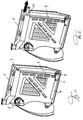
- the backrest part 1 shown in FIG. 1 of a partially foldable motor vehicle rear seat can be folded over at least one laterally arranged joint 2 and can be folded into different positions.
- a side one Lock 6 available, for example, in the load-bearing parts of the passenger compartment the C-pillar or the vehicle floor engages.
- an additional locking device 3 On the side of the backrest part 1 there is an additional locking device 3, which is in the standby position in this illustration.
- To trigger the additional lock 3 is transverse to the direction of travel in or along of the frame of the backrest part 1 with a gas generator 4 as an energy store an acceleration sensor 5 for triggering it when exceeding one in Acceleration limit determined in the direction of travel.
- a gas generator 4 as an energy store an acceleration sensor 5 for triggering it when exceeding one in Acceleration limit determined in the direction of travel.
- the pressure of the gas generated by the gas generator 4 is used, to actuate a pulling device 7, which acts on the additional locking means 3 and brings this into the locked position, so that a bond between the two Backrest parts 1 is produced.
- the blocking signal can be preferred lock the acceleration sensor 5 or the gas generator 4.
- FIG. 2 differs by a pressure line 9, the gas pressure to one in place of the traction device 7 Actuating cylinder, not shown, in which a working piston on the Lock bolt 10, the additional locking 3 acts.
- the actuating cylinder is here in the frame of the backrest part 1 in the direction indicated by the arrow 11 is aligned.
- the locking bolt 10 has a locking lug, which the connection security of the additional locking 3 and thus the the backrest parts 1 holding forces increased.
- this example is as the example according to FIG. 1, for which the locking bolt 10 can be used.
- the acting as an active locking bolt Latch bolt 10 made a bond between the backrest parts.
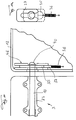
- each used Backrest part 1 at least one pull rope 13, which is connected to the upper backrest area is connected and normally loose to a mechanical traction device 14, into which a gas generator is integrated as an energy store, is guided (FIG. 3).
- the two pull cables 13 for the respective backrest parts 1 have a free one Length without folding the backrest parts 1 to the desired extent Disability enables.
- the traction cables 13 are tensioned by the traction device 14 and are kept taut so that the backrest parts 1 in addition to a movement are hindered in the direction of travel. Otherwise, the gas generator can be triggered or the traction device 14 with a sensor, as in the example, that was described in Figures 1 and 2, is the case.
- the triggering in a further example can also be a Additional locking take place, which is shown in Figures 5 and 6.
- a pushing device 15 is attached to each backrest part 1, in which an integrated gas generator can also be provided.
- the pusher 15 are only included in Fig. 6 visible bars 16, the after triggering the thrust device 15 or gas generator in the direction of in Vehicle chassis existing recordings are moved and a tilt or Preventing unique flaps even in the event of greater loads in the pushing device 15 and the catch 16 engaging in the receptacle, which form the additional locking means.
- the receptacles for the bolts 16 are in the vehicle floor arranged behind the backrest parts 1, but they can also on others suitable parts of the vehicle chassis may be provided.
- a reversal of the direction of thrust and arrangement of the recordings is also possible when the pusher 15 on the vehicle chassis and the recordings located on the backrest parts 1.
- the embodiment of the additional locking device 3 shown in FIG. 7 has the locking bolt 10.
- the locking bolt 10 is displaceable in its axial direction housed in one of the two backrests.
- the additional locking 3 in the 40% backrest 1 of the Motor vehicle rear seat.
- the locking bolt 10 is in this a longitudinal guide 23 in the axial direction.
- the lock 18 designed as a locking lever is connected to a Bowden cable 24 with a Acceleration sensor 21, which is shown in detail in FIG. 8, connected.
- the acceleration sensor 21 has a sensor lever 25.
- the sensor lever 25 is designed as a two-sided lever that is pivotable about an axis 26.
- an engagement part 27 is provided, which is in locking engagement with a sensor bar 28 connected to the Bowden cable 24 in the rest position stands. This state is shown in FIG. 8.
- the force of the spring 17 exerts over the axis 29 pivotable locking lever of the lock 18 and the Bowden cable 24 a force on the Point of engagement between the sensor latch 28 and the engagement part 27 of the sensor lever 25 in the direction of the Bowden cable.
- the locking lever of the lock 18 is designed as a two-armed lever, with the Bowden cable on one lever arm 24 engages and on the other lever arm the engagement part 30 is provided, the on the stop part 31, which is formed on the locking bolt 10, in the illustrated Rest position is present.
- a sensor mass 32 is provided on the second lever arm of the sensor lever 25.
- the sensor mass 32 of the second lever arm is supported by a sensor spring 33 on a stationary sensor housing 34.
- the sensor lever 25 is arranged that its longitudinal extent is transverse to the longitudinal direction of the vehicle. He can in be provided in the horizontal direction on the backrest part 1.
- one Sensor lock 42 is provided, which release the engagement of the sensor lever 25 in the sensor bar 28 e.g. prevented during transport and during assembly work. This lock is released after final assembly.
- the acceleration sensor speaks in the event of excessive acceleration or deceleration 21 on.
- the sensor mass 32 against the force of the sensor spring 33 pivoted about the axis 26.
- the engaging part provided on the other lever arm 27 is disengaged from the sensor bar 28 about the axis 26 pivoted.
- the lock 18 is thus released and the force of the spring 17 is released. Due to the force of the spring 17, the locking bolt 10 in FIGS. 7 and 9 shifted to the right in its longitudinal guide 23.
- the locking lever the lock 18 is pivoted about the axis 29 so that the engagement part 30th disengages from the stop 31.
- the locking bolt 10 has a bolt head 40 at its front end. This moves through a cream opening 35 a locking element biased by a locking spring 36 37 in the form of a locking board.
- the locking element 37 is in the rest position by a in the receiving opening 35 arranged retaining bolt 38 in the prestressed rest position held.
- the holding bolt 38 protrudes through corresponding openings in a guide 39, for example in the form of two guide boards, between which the Locking element 37 is guided.
- the locking element becomes the locking element 37 in the rest position shown in FIG. 9 between the held two boards of the guide device 39.
- the receiving opening 35 is designed so that the locking head 40 at the top of the Bolt 10 when driven by the spring 17 through the receiving opening 35 is moved through, the retaining bolt 38 from its holding position is pushed out.
- the locking bolt 10 and the locking head 40 then take the position shown in FIG. 10.
- the guide device 39, in the the receiving plate 35 is also provided, forms one Recording for the locking bolt 10.
- the guide device 39, which together with the plate-shaped locking element a receptacle 46 for the Lock bolt 10 forms in its locking position, is in the other Backrest part 12. In the exemplary embodiment shown, this is a backrest part 12 designed as a 60% backrest part of the vehicle rear seat.
- locking element 37 slidably mounted in the guide unit 39 is pulled down due to the force of the locking spring 36 (arrow 47), after the holding bolt 38 is removed from its holding position.
- the platinum-shaped To this end, locking element 37 has at the receiving opening 35 a narrowed elongated hole 41, the width of which is smaller than that Diameter of the bolt head 40.
- the width of the elongated hole 41 is dimensioned that the part of the locking bolt 10 adjoining the locking head 40 is unobstructed can protrude as shown in Fig. 10. This gives you a pre-sprung positive locking of the locking bolt 10 in the other Backrest part 12.
- the positively locked bolt 10 is a positive train connection between the two back parts 1 and 12 reached. This form-fitting train combination ensures protection against Thrust caused by moving cargo behind the back seat in the Vehicle is arranged arise.
- the interlocking train connection with pre-sprung positive locking is used for the exemplary embodiments shown in FIGS. 7 to 10, that the locking bolt 10 is guided in a back part 1 and through the force of the spring 17 acting as an energy accumulator in the direction of a bolt receptacle 46 is moved in the other back part 12.
- the bolt receptacle 46 contains the pre-sprung positive lock in the form of the guide device 39 with the locking element 37 standing under the spring load.
Landscapes
- Engineering & Computer Science (AREA)
- Mechanical Engineering (AREA)
- Aviation & Aerospace Engineering (AREA)
- Transportation (AREA)
- Seats For Vehicles (AREA)
- Air Bags (AREA)
Claims (11)
- Dispositif de verrouillage de dossiers divisibles rabattables de sièges arrières de véhicules automobiles qui sont tenus dans la positon normale sur la structure de véhicule, a l'aide de dispositifs d'arrêt associés, au moins un dispositif d'arrêt supplémentaire (3; 10; 13; 16) qui peut être déclenché par un capteur d'accélération (5; 21) et agit sur deux parties de dossier (1, 12) étant prévu, caractérisé par le fait que le capteur d'accélération (5; 21) libère un accumulateur de force (4; 17) qui actionne le dispositif d'arrêt supplémentaire (3; 10; 13; 16).
- Dispositif selon la revendication 1, caractérisé par le fait qu'au moins un capteur supplémentaire (8) pour détecter la position des parties de dossier (1) est disposé sur le dossier.
- Dispositif selon la revendication 1 ou 2, caractérisé par le fait que le dispositif d'arrêt supplémentaire (3; 10) forme un lien entre deux parties de dossier.
- Dispositif selon une des revendications 1 à 3, caractérisé par le fait qu'au moins le dispositif d'arrêt supplémentaire comporte un verrou (10; 16) qui peut être déplacé par un dispositif de poussée (15; 17).
- Dispositif selon la revendication 4, caractérisé par le fait que le verrou (10; 16) concerné, après déclenchement du dispositif de poussée (15; 17), pénètre par complémentarité de formes dans un logement.
- Dispositif selon une des revendications 1 à 5, caractérisé par le fait que l'/les élément(s) de blocage est/sont agencé(s) sous forme de verrou(s) actif(s).
- Dispositif selon une des revendications 1 à 6, caractérisé par le fait que le dispositif d'arrêt supplémentaire (3; 10; 16) déclenché est verrouillé par force.
- Dispositif selon une des revendications 1 à 7, caractérisé par le fait que le dispositif d'arrêt supplémentaire comporte une tige de verrou (10) précontrainte par un ressort (17), qui est maintenue dans la position de repos par un dispositif de retenue (18) déclenchable par le capteur d'accélération (5).
- Dispositif selon une des revendications 1 à 8, caractérisé par le fait que le dispositif d'arrêt supplémentaire peut être déplacé en direction de la position de verrouillage à l'encontre d'une force de rappel.
- Dispositif selon une des revendications 1 à 9, caractérisé par le fait que le verrou (10) est prévu dans une partie de dossier (1) et qu'un logement (46) pour le verrou, dans la position de verrouillage de celui-ci est prévu dans l'autre partie de dossier (12).
- Dispositif selon une des revendications 1 à 10, caractérisé par le fait que le verrou (10) peut être déplacé dans une position d'attente de verrouillage.
Applications Claiming Priority (2)
| Application Number | Priority Date | Filing Date | Title |
|---|---|---|---|
| DE4427835 | 1994-08-05 | ||
| DE4427835A DE4427835A1 (de) | 1994-08-05 | 1994-08-05 | Arretierung für geteilt klappbare Rückenlehnen von Kraftfahrzeugrücksitzen |
Publications (3)
| Publication Number | Publication Date |
|---|---|
| EP0697307A2 EP0697307A2 (fr) | 1996-02-21 |
| EP0697307A3 EP0697307A3 (fr) | 1997-04-02 |
| EP0697307B1 true EP0697307B1 (fr) | 1999-01-20 |
Family
ID=6525053
Family Applications (1)
| Application Number | Title | Priority Date | Filing Date |
|---|---|---|---|
| EP95106842A Expired - Lifetime EP0697307B1 (fr) | 1994-08-05 | 1995-05-05 | Dispositif de verrouillage pour dossiers divisible et escamotable dans un siège arrière pour véhicules automobiles |
Country Status (3)
| Country | Link |
|---|---|
| EP (1) | EP0697307B1 (fr) |
| DE (2) | DE4427835A1 (fr) |
| ES (1) | ES2128608T3 (fr) |
Families Citing this family (12)
| Publication number | Priority date | Publication date | Assignee | Title |
|---|---|---|---|---|
| DE19540395C2 (de) * | 1995-10-30 | 1998-06-04 | Daimler Benz Ag | Sitz für Fahrzeuge |
| GB2316304B (en) * | 1996-08-14 | 2000-03-29 | Autoliv Dev | Improvements in or relating to a back support for a vehicle seat |
| DE19701775C2 (de) | 1997-01-20 | 2002-01-17 | Kendrion Rsl Germany Gmbh | Vorrichtung zum Verriegeln von geteilt klappbaren Rückenlehnen an Kraftfahrzeugrücksitzen |
| DE29805901U1 (de) * | 1998-03-31 | 1998-07-30 | TRW Occupant Restraint Systems GmbH & Co. KG, 73553 Alfdorf | Baugruppe aus einer umklappbaren Rückenlehne und einer Arretiervorrichtung |
| DE19846633C1 (de) * | 1998-10-09 | 1999-09-23 | Schmidt Gmbh R | Vorrichtung zum Verriegeln von geteilt klappbaren Rückenlehnen von Rücksitzen eines Kraftfahrzeugs |
| DE19926524A1 (de) * | 1999-06-10 | 2000-12-14 | Volkswagen Ag | Klappbare Rücksitzlehne |
| IT1311272B1 (it) * | 1999-12-23 | 2002-03-12 | Fiat Auto Spa | Dispositivo gonfiabile di ritenuta per il vano bagagli di unautoveicolo. |
| DE10022984B4 (de) * | 2000-05-05 | 2016-07-28 | Volkswagen Ag | Rückenlehne für einen Kraftfahrzeugsitz |
| DE102005003288A1 (de) * | 2005-01-25 | 2006-07-27 | Keiper Gmbh & Co.Kg | Fahrzeugsitz mit schwenkbarer Klappe |
| JP4195053B2 (ja) * | 2006-11-21 | 2008-12-10 | アイシン精機株式会社 | 車両用シート装置 |
| US9376078B1 (en) | 2015-01-20 | 2016-06-28 | Ford Global Technologies, Llc | Seat mechanism inertia locking system |
| CN107336644A (zh) * | 2017-06-27 | 2017-11-10 | 浙江零跑科技有限公司 | 一种汽车后排座椅靠背解锁结构 |
Family Cites Families (7)
| Publication number | Priority date | Publication date | Assignee | Title |
|---|---|---|---|---|
| US4305615A (en) * | 1978-03-07 | 1981-12-15 | Keiper U.S.A., Inc. | Vehicle seat back mounting |
| DE3026259A1 (de) * | 1980-07-11 | 1982-02-04 | Adam Opel AG, 6090 Rüsselsheim | Nach vorn umklappbare rueckenlehne von fahrzeugsitzen |
| DE3211363A1 (de) * | 1982-03-27 | 1983-10-13 | Adam Opel AG, 6090 Rüsselsheim | Verriegelung fuer eine geteilte hintersitz-rueckenlehne eines kraftfahrzeuges |
| FR2629767B1 (fr) * | 1988-04-07 | 1991-03-15 | Ecia Equip Composants Ind Auto | Banquette repliable et notamment banquette arriere de vehicule automobile |
| CA2064490C (fr) * | 1992-03-31 | 1996-01-23 | Daniel Hughes | Mecanisme de verrouillage a inertie, a ressort, pour siege de vehicule assembles |
| DE4230538C2 (de) * | 1992-09-10 | 1997-04-03 | Stephan Kaszynski | Stabilisierungseinrichtung für geteilte, umklappbare Rücksitzlehnen in Kraftfahrzeugen |
| JP3290489B2 (ja) * | 1993-01-20 | 2002-06-10 | マツダ株式会社 | 自動車のシート装置 |
-
1994
- 1994-08-05 DE DE4427835A patent/DE4427835A1/de not_active Withdrawn
-
1995
- 1995-05-05 DE DE59504878T patent/DE59504878D1/de not_active Expired - Lifetime
- 1995-05-05 ES ES95106842T patent/ES2128608T3/es not_active Expired - Lifetime
- 1995-05-05 EP EP95106842A patent/EP0697307B1/fr not_active Expired - Lifetime
Also Published As
| Publication number | Publication date |
|---|---|
| ES2128608T3 (es) | 1999-05-16 |
| DE4427835A1 (de) | 1996-02-08 |
| EP0697307A2 (fr) | 1996-02-21 |
| DE59504878D1 (de) | 1999-03-04 |
| EP0697307A3 (fr) | 1997-04-02 |
Similar Documents
| Publication | Publication Date | Title |
|---|---|---|
| DE69310985T2 (de) | Federbelastete Vorrichtung zur Trägheitsverriegelung von Fahrzeugsitzen | |
| DE4010209C2 (de) | Sicherheitsnetz | |
| DE3726711C2 (fr) | ||
| DE19540395C2 (de) | Sitz für Fahrzeuge | |
| EP0563562B1 (fr) | Système de chargement de fret | |
| DE19738130A1 (de) | Vorrichtung zum Sichern von Fracht oder Gepäck in einem Fracht- oder Gepäckraum | |
| EP1608529A1 (fr) | Ensemble appui-tete pour un siege de vehicule automobile | |
| EP0752344A1 (fr) | Arceau de sécurité télescopique | |
| EP0709248B1 (fr) | Siège de véhicule automobile à dossier rabattable vers l'avant | |
| EP0697307A2 (fr) | Dispositif de verrouillage pour dossiers divisible et escamotable dans un siège arrière pour véhicules automobiles | |
| DE19740776C1 (de) | Umklappbare Rückenlehne für eine Sitzbank | |
| EP0916552B1 (fr) | Arceau de sécurité déployable pour véhicules | |
| DE10030822C2 (de) | Kraftfahrzeugsitz mit nach vorn klappbarer Rückenlehne | |
| DE102006028664B4 (de) | Überrollschutzsystem für ein Kraftfahrzeug | |
| EP0770540B1 (fr) | Véhicule automobile avec sièges à dossiers rabattables | |
| DE19708395A1 (de) | Vorrichtung zur Befestigung von Kindersitzen | |
| DE10332912B3 (de) | Entriegelungsvorrichtung für einen Fahrzeugsitz | |
| EP1057696A2 (fr) | Dispositif à arceau de sécurité pour véhicules | |
| EP1736371B1 (fr) | Véhicule avec système de protection en cas de retournement | |
| DE19926524A1 (de) | Klappbare Rücksitzlehne | |
| EP1227011A2 (fr) | Système d'arceau de sécurité pour véhicules automobiles | |
| DE102005028879B4 (de) | Überrollschutzsystem für ein Kraftfahrzeug | |
| DE102005028966B4 (de) | Kraftfahrzeug mit einem Überrollschutzsystem an einer Fahrzeugquerwand | |
| DE102007028500A1 (de) | Vorrichtung zur karosserieseitigen Verriegelung einer Lehne eines Fahrzeugsitzes in unterschiedlichen Neigungspositionen | |
| DE10354161B4 (de) | Vorrichtung zur Verriegelung einer Fahrzeuglehne in wenigstens zwei unterschiedlichen Lehnenpositionen |
Legal Events
| Date | Code | Title | Description |
|---|---|---|---|
| PUAI | Public reference made under article 153(3) epc to a published international application that has entered the european phase |
Free format text: ORIGINAL CODE: 0009012 |
|
| AK | Designated contracting states |
Kind code of ref document: A2 Designated state(s): DE ES FR GB IT SE |
|
| RBV | Designated contracting states (corrected) |
Designated state(s): DE ES FR GB IT SE |
|
| RAP1 | Party data changed (applicant data changed or rights of an application transferred) |
Owner name: ADAM OPEL AG |
|
| RIN1 | Information on inventor provided before grant (corrected) |
Inventor name: LEUCHTMANN, ANDREW, DIPL.-ING. Inventor name: SPECHT, MARTIN |
|
| PUAL | Search report despatched |
Free format text: ORIGINAL CODE: 0009013 |
|
| AK | Designated contracting states |
Kind code of ref document: A3 Designated state(s): DE ES FR GB IT SE |
|
| 17P | Request for examination filed |
Effective date: 19970712 |
|
| 17Q | First examination report despatched |
Effective date: 19971212 |
|
| GRAG | Despatch of communication of intention to grant |
Free format text: ORIGINAL CODE: EPIDOS AGRA |
|
| GRAG | Despatch of communication of intention to grant |
Free format text: ORIGINAL CODE: EPIDOS AGRA |
|
| GRAH | Despatch of communication of intention to grant a patent |
Free format text: ORIGINAL CODE: EPIDOS IGRA |
|
| GRAH | Despatch of communication of intention to grant a patent |
Free format text: ORIGINAL CODE: EPIDOS IGRA |
|
| GRAA | (expected) grant |
Free format text: ORIGINAL CODE: 0009210 |
|
| AK | Designated contracting states |
Kind code of ref document: B1 Designated state(s): DE ES FR GB IT SE |
|
| REF | Corresponds to: |
Ref document number: 59504878 Country of ref document: DE Date of ref document: 19990304 |
|
| ET | Fr: translation filed | ||
| GBT | Gb: translation of ep patent filed (gb section 77(6)(a)/1977) |
Effective date: 19990315 |
|
| REG | Reference to a national code |
Ref country code: ES Ref legal event code: FG2A Ref document number: 2128608 Country of ref document: ES Kind code of ref document: T3 |
|
| PLBE | No opposition filed within time limit |
Free format text: ORIGINAL CODE: 0009261 |
|
| STAA | Information on the status of an ep patent application or granted ep patent |
Free format text: STATUS: NO OPPOSITION FILED WITHIN TIME LIMIT |
|
| 26N | No opposition filed | ||
| REG | Reference to a national code |
Ref country code: GB Ref legal event code: IF02 |
|
| REG | Reference to a national code |
Ref country code: GB Ref legal event code: 732E Free format text: REGISTERED BETWEEN 20090219 AND 20090225 |
|
| REG | Reference to a national code |
Ref country code: GB Ref legal event code: 732E Free format text: REGISTERED BETWEEN 20090305 AND 20090311 |
|
| REG | Reference to a national code |
Ref country code: GB Ref legal event code: 732E Free format text: REGISTERED BETWEEN 20091029 AND 20091104 |
|
| REG | Reference to a national code |
Ref country code: GB Ref legal event code: 732E Free format text: REGISTERED BETWEEN 20091105 AND 20091111 |
|
| REG | Reference to a national code |
Ref country code: DE Ref legal event code: R081 Ref document number: 59504878 Country of ref document: DE Owner name: GM GLOBAL TECHNOLOGY OPERATIONS LLC (N. D. GES, US Free format text: FORMER OWNER: GM GLOBAL TECHNOLOGY OPERATIONS, INC., DETROIT, MICH., US Effective date: 20110323 Ref country code: DE Ref legal event code: R081 Ref document number: 59504878 Country of ref document: DE Owner name: GM GLOBAL TECHNOLOGY OPERATIONS LLC (N. D. GES, US Free format text: FORMER OWNER: GM GLOBAL TECHNOLOGY OPERATIONS, INC., DETROIT, US Effective date: 20110323 |
|
| PGFP | Annual fee paid to national office [announced via postgrant information from national office to epo] |
Ref country code: SE Payment date: 20110512 Year of fee payment: 17 |
|
| PGFP | Annual fee paid to national office [announced via postgrant information from national office to epo] |
Ref country code: IT Payment date: 20110517 Year of fee payment: 17 |
|
| PGFP | Annual fee paid to national office [announced via postgrant information from national office to epo] |
Ref country code: DE Payment date: 20120502 Year of fee payment: 18 |
|
| PGFP | Annual fee paid to national office [announced via postgrant information from national office to epo] |
Ref country code: FR Payment date: 20120608 Year of fee payment: 18 Ref country code: GB Payment date: 20120502 Year of fee payment: 18 |
|
| PGFP | Annual fee paid to national office [announced via postgrant information from national office to epo] |
Ref country code: ES Payment date: 20120607 Year of fee payment: 18 |
|
| REG | Reference to a national code |
Ref country code: SE Ref legal event code: EUG |
|
| PG25 | Lapsed in a contracting state [announced via postgrant information from national office to epo] |
Ref country code: IT Free format text: LAPSE BECAUSE OF NON-PAYMENT OF DUE FEES Effective date: 20120505 Ref country code: SE Free format text: LAPSE BECAUSE OF NON-PAYMENT OF DUE FEES Effective date: 20120506 |
|
| GBPC | Gb: european patent ceased through non-payment of renewal fee |
Effective date: 20130505 |
|
| PG25 | Lapsed in a contracting state [announced via postgrant information from national office to epo] |
Ref country code: DE Free format text: LAPSE BECAUSE OF NON-PAYMENT OF DUE FEES Effective date: 20131203 |
|
| REG | Reference to a national code |
Ref country code: FR Ref legal event code: ST Effective date: 20140131 |
|
| PG25 | Lapsed in a contracting state [announced via postgrant information from national office to epo] |
Ref country code: GB Free format text: LAPSE BECAUSE OF NON-PAYMENT OF DUE FEES Effective date: 20130505 |
|
| REG | Reference to a national code |
Ref country code: DE Ref legal event code: R119 Ref document number: 59504878 Country of ref document: DE Effective date: 20131203 |
|
| PG25 | Lapsed in a contracting state [announced via postgrant information from national office to epo] |
Ref country code: FR Free format text: LAPSE BECAUSE OF NON-PAYMENT OF DUE FEES Effective date: 20130531 |
|
| REG | Reference to a national code |
Ref country code: ES Ref legal event code: FD2A Effective date: 20140609 |
|
| PG25 | Lapsed in a contracting state [announced via postgrant information from national office to epo] |
Ref country code: ES Free format text: LAPSE BECAUSE OF NON-PAYMENT OF DUE FEES Effective date: 20130506 |