EP0697338A1 - Verpackung für ein Produkt nichtspezifischer Form, Satz von Zuschnitten, Verfahren und Vorrichtung zur Herstellung einer solchen Verpackung - Google Patents
Verpackung für ein Produkt nichtspezifischer Form, Satz von Zuschnitten, Verfahren und Vorrichtung zur Herstellung einer solchen Verpackung Download PDFInfo
- Publication number
- EP0697338A1 EP0697338A1 EP95401819A EP95401819A EP0697338A1 EP 0697338 A1 EP0697338 A1 EP 0697338A1 EP 95401819 A EP95401819 A EP 95401819A EP 95401819 A EP95401819 A EP 95401819A EP 0697338 A1 EP0697338 A1 EP 0697338A1
- Authority
- EP
- European Patent Office
- Prior art keywords
- tray
- flaps
- flap
- blank
- packaging
- Prior art date
- Legal status (The legal status is an assumption and is not a legal conclusion. Google has not performed a legal analysis and makes no representation as to the accuracy of the status listed.)
- Granted
Links
Images



Classifications
-
- B—PERFORMING OPERATIONS; TRANSPORTING
- B65—CONVEYING; PACKING; STORING; HANDLING THIN OR FILAMENTARY MATERIAL
- B65D—CONTAINERS FOR STORAGE OR TRANSPORT OF ARTICLES OR MATERIALS, e.g. BAGS, BARRELS, BOTTLES, BOXES, CANS, CARTONS, CRATES, DRUMS, JARS, TANKS, HOPPERS, FORWARDING CONTAINERS; ACCESSORIES, CLOSURES, OR FITTINGS THEREFOR; PACKAGING ELEMENTS; PACKAGES
- B65D5/00—Rigid or semi-rigid containers of polygonal cross-section, e.g. boxes, cartons or trays, formed by folding or erecting one or more blanks made of paper
- B65D5/42—Details of containers or of foldable or erectable container blanks
- B65D5/44—Integral, inserted or attached portions forming internal or external fittings
- B65D5/50—Internal supporting or protecting elements for contents
- B65D5/5028—Elements formed separately from the container body
Definitions
- the present invention relates to a composite packaging packaging for a product of non-specific type of type comprising a box of polygonal cross section made of sheet material of cardboard or corrugated cardboard, comprising a belt of side flaps, a bottom and a top, and a sheet. or a heat-shrinkable plastic bag, fixed to said box by gluing, blocking by heat-contraction of the product or products against the bottom.
- It also relates to a set of blanks, a device and a method for obtaining such packaging.
- Packages are already known for packaging in a film of heat-shrinkable plastic material of at least one product of the type defined above.
- the document FR 2.625.181 describes for example a package where the film is glued to the bottom of the package and folded over the products to be held against the bottom.
- FR-A-2 577 519 is a packaging with shrink film in two parts, base and cover.
- Heating these packages to obtain heat shrinkage is also difficult to implement given the structural difficulties, linked to the packaging, of circulation of a convective fluid around the film to be shrunk.
- the present invention aims to provide a packaging, a set of blanks, a method and a packaging device for products of non-specific shape, which meet the requirements of practice better than those previously known, in particular in that it allows automatic manufacture. packaging, optimized heating of the film to be shrunk, while guaranteeing excellent fixing of the film or plastic bag on the cardboard box.
- the resistance to tearing or shearing of the connections between plastic sheet and internal walls is improved, which avoids separation between products and box when the packaging is subject to shocks, drops or overturning, especially during handling.
- the invention provides in particular a composite packaging packaging for at least one product of non-specific shape not occupying the entire available volume of the packaging, comprising a box of polygonal cross section made of cardboard sheet material or corrugated cardboard, comprising a belt, a bottom and a top, and a sheet or a bag of heat-shrinkable plastic, fixed to said box by gluing, blocking by heat-constriction of the product or products against the bottom, characterized in that the box comprises an intermediate box in the form of an inverted tray, the walls of which at least partially form said belt and the bottom of which is perforated, the film or the bag being fixed to the peripheral edges of two opposite walls of said tray, said tray being wrapped at least in part by a sheet forming the bottom of the package and fixed to said tray by gluing.
- each of said series of enveloping flaps comprises a second enveloping flap, at the end, capable of being folded down on the upper external face of the tray by folding to form at least partially the cover of the packaging.
- one of said series of enveloping flaps comprises a single flap and the other series comprises at least two.
- the other series has three components.
- the width of an enveloping flap or the sum of the respective widths of the two end enveloping flaps is equal or substantially equal to the width of the central flap of the tray on which the said enveloping flap or flaps 'end are arranged to be glued to form the cover of the package.
- the width of the two second opposite lateral flaps devoid of secondary flap is smaller than that of the first two lateral flaps.
- the means for forming the first assembly comprise means for folding a blank to form the tray and means for bringing and bonding the film or the bag to the peripheral edges of the tray thus formed.
- the means for forming the first assembly comprise means for bonding the film or the plastic bag to the flat blank intended to form said tray, then means for shaping the assembly for obtain said tray internally covered with film by folding.
- the means for bonding the film or the bag to the tray are arranged to glue said film or said bag to the internal peripheral edges of two opposite walls of the tray.
- the means for bonding the film or the bag to the tray are arranged to adhere said film or said bag to the outer peripheral edges of two opposite walls of the tray.
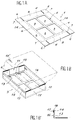
- FIG. 1A shows a blank 1 of corrugated cardboard comprising a perforated central rectangular panel 2, for example having four identical rectangular windows 3, symmetrically distributed, the sum of the areas of which occupies substantially 9/10 of the surface of said panel.
- the central flap 2 is provided with four rectangular lateral flaps respectively connected to the four sides of said central flap by first fold lines 4, namely two first opposite lateral flaps 5, each provided with two secondary end flaps 6, rectangular, of the same width as said first flaps 5, located in the extension of those -this, and connected on either side of said first lateral flaps by second fold lines 7 perpendicular to the first fold lines of the same flaps, and two second opposite lateral flaps 8, without secondary flaps, of the same width as the secondary flaps of the first lateral flaps.
- FIG. 1B shows a first assembly 9 belonging to a package according to the invention, comprising a tray 10 obtained from the folded blank 1, the secondary flaps 6 of which have been glued to the internal face 11 of the second flaps 8, the lines of folding 7 and 4 being slightly offset accordingly.
- the secondary flaps can be glued to the external face 12 of the second flaps; in this case, the offset between fold lines is in the opposite direction.
- the assembly 9 further comprises a plastic film 13 (in phantom 13 ') brought on top of the tray 10 which has been shaped.
- the film 13 is rectangular, of width substantially equal to a dimension of the central flap 2, for example the length thereof, and of length greater than the length of the blank 1 obtained by adding the other dimension of the central flap and lengths of the first two parts 5.
- the film is fixed on the peripheral edges 14 of the first flaps 5, on the external part 16 of the walls of the tray thus formed, by lines of glue 17 (see FIG. 1B '), the peripheral edge 18 of the film therefore being astride. on the edges 14 of the first flaps 5, and the two other opposite peripheral edges 19 of the film substantially coinciding with the fold lines 4 of the bottom of the tray.
- FIG. 2A shows the blank 1 on which this time comes first of all fixing the film 13 by gluing on the internal face 20 of the first flaps 5 along the peripheral edges 14 (glue line 21) of said first flaps, before folding, to obtain, after folding, the assembly 9 with film glued internally as shown in Figures 2B and 2B '.
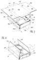
- FIG. 3 shows the assembly 9 (tray 10 + film 13) in which products 22 of different shapes have been placed, on which a sheet of corrugated cardboard 23 is placed to form the bottom of the packaging after turning over ( see figure 4).
- the sheet 23 is constituted by a blank comprising a rectangular main flap 24, suitable for forming the bottom of the packaging, provided with two identical end side flaps 25, opposite in the transverse direction of the blank, rectangular or trapezoidal. of small base directed outwards, connected by lines of folding 26 to said main flap, the distance between the folding lines 26 being arranged to allow the open face 27 of the tray 10 to be covered, taking account of the cumulative thicknesses of the flaps 8.
- the blank also comprises two series 28 and 29 of rectangular flaps of transverse dimension identical or slightly less than that of the main flap 24, located on either side of the main flap 24 connected to each other by parallel fold lines 30 .
- Each series comprises a first enveloping shutter 31, rectangular, covering a wall 32 of the tray on which is fixed the film of heat-shrinkable plastic 13 and a second wrapping shutter 33, suitable for being folded down on the external face of the bottom of the tray.
- FIG. 4 shows the assembly 34 obtained after gluing on the one hand of the lateral end flaps 25 on the second flaps 8, and on the other hand of the first enveloping flaps 31 on the external face of the walls 32 and turning over, the second enveloping flaps 33 remaining open to allow, via the windows 3 at the bottom of the tray, access to the heat transfer fluid towards the heat-shrinkable film.
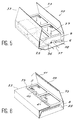
- FIG. 5 shows a variant 35 of the assembly of FIG. 4, in which the length of the second opposite lateral flaps 8 devoid of secondary flap, is smaller than that of the first two lateral flaps 5 and of their secondary end flaps 6 which leaves a passage 36 for circulation of a heat-transfer fluid (arrow 37) above the internal face 38 of the main flap 24, before closing and gluing the side end flaps 25.
- FIG. 6 shows the embodiment of the packaging according to the invention more particularly described here at the time of its complete closure, after heat-shrinking of the plastic film 13 on the products 22.
- the second flaps 33 previously glued with lines of glue 39, for example of glue called "hot melt” or cold glue, continuous or interrupted, 39 on their respective internal peripheral end parts, are pressed on the external face of the central flap 2, perforated, which comprises opposite lines of glue, a non-perforated part 40 to cooperate with said glued end parts.
- lines of glue 39 for example of glue called "hot melt” or cold glue, continuous or interrupted, 39 on their respective internal peripheral end parts
- edges 41 of the end parts of the two flaps 33 are for example contiguous once said flaps folded over the bottom 2, which gives a finished appearance and ensures good solidity and integrity of the packaging obtained.
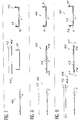
- FIG. 7 shows a first step 42 of bringing in the blank 1, a second step 43 of forming the tray 10 and of bringing film 13 or the bag 44 above said tray, and a third step 45 for bonding the film 13 to the tray, the external faces 16 of two walls of which have been glued beforehand.
- FIG. 7 corresponds to that described with reference to lines 1A, 1B and 1B '.
- Figure 8 corresponds to the process mentioned with reference to Figures 2A, 2B and 2B '.
- It comprises a first step 46 of bringing film 13 or bag 44 onto the flat blank 1, the film being substantially the same width as the blank, a second step 47 of bonding the film to said flat blank whose edges internal peripherals 14 were previously glued, then a third step 48 of forming the tray, the film then marrying the internal faces of said tray to give the first set 9.
- FIG. 9 shows an embodiment of the method combining bonding on the internal and external edges of the first flaps 5.
- the first step 49 is identical to step 46. Then, after gluing of the internal and external peripheral edges of the blank, the film 13 is wider (step 50) than the blank on the latter, then the ends are folded down 51 of the film around the edges, and the tray is erected (step 52) to obtain an assembly with double bonding, internal and external, of the film on the peripheral edges 14 of the first flaps 5.
- FIG. 10 shows the last two steps of the method according to the invention more particularly described here, namely step 52 of heating by heat transfer fluid 53, for example blown from above, and drawn in at 54 from the sides, then from the bottom of the packaging, and step 55 of closing the flaps 33 and gluing on a central tongue 56 of the perforated bottom of the tray.
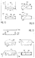
- FIG. 11 schematically shows in section two packages according to the invention with variant cover, namely a package 57 with two rectangular end flaps 58 of the same width, the edges 59 of which are joined, in the center of the package, when '' they are glued to the central tab 60, separating the openings from the perforated bottom 61, and a package 62 comprising a small end flap 63 of small width, for example equal to one tenth of the total width of the package, and a large flap 64 substantially covering the entire bottom 65 of the inverted tray.
- FIG 12 there is shown schematically the stages of manufacturing a package according to the invention with a bag or bag 66.
- the bag 66 is for example glued to the preformed tray 67 with perforated bottom, on the outer edge of two vertical walls 68 facing the tray. Then the bag 66 is opened by the sides 69, and filled with products 70.
- the cover 71 is then put in place to close the second set, which is turned over, then the bag is shrunk by heat on the products before the flaps 72 are closed.
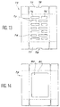
- FIG. 13 shows a blank 73 for constituting a tray for packaging according to the invention.
- the bottom 74 is perforated by a series of rows 75 of longitudinal windows 76, for example seven rows of two rectangular windows each, namely a small window and a large window staggered from row to row.
- the second flaps 77 devoid of secondary flaps of the blank comprise a notch 78, for example rectangular, centered, on the peripheral edge of said flap, which will allow circulation of the heat transfer fluid during heating, along the plastic film.
- FIG. 14 shows another blank 79 for a tray according to the invention with a central opening 80 occupying 8/10 of the surface of the central flap 81.
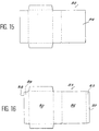
- FIGS. 15 and 16 respectively show two blanks 82 and 83 for forming the bottom of the package according to the invention, namely a blank 82 provided with an end flap 84 suitable for completely covering the bottom of the inverted tray , and a blank 83 provided with an end flap 85 in the extension of the flaps 86 suitable for completely covering the bottom of the tray, arranged to come to cover a vertical wall of said tray and whose edge 87 comes to cooperate joined or substantially contiguously with the edge 88 of the flap 89 located on the opposite side of the central flap 90 of the blank 83, relative to said central flap 90.
- FIG. 17 shows means 91 for forming a first assembly 92 comprising a corrugated cardboard tray 93 and a film of heat-shrinkable plastic 94 (in phantom in the figure).
- these means 91 comprise a device 95 for vertical storage and unstacking of blanks 96 capable of forming said tray, known in itself.
- the blanks 96 are deposited one by one on a conveyor belt 97 which moves the blank transversely to bring it below a machine 98 suitable for punching, by lowering a piston 99 of a shape complementary to that of the internal volume of the tray , said blank towards a position 100 after guiding inside a shaping well 101, so as to obtain the formed tray 93.
- Sizing means 102 known in themselves have previously made it possible to glue the flaps of the blank so that the flaps of the tray can be glued to one another as described above.
- the tray 93 is then brought by means of a conveyor belt 103 (in phantom in Figure 17) to a position for placing the plastic film.
- glue injectors When transferring to 104, glue injectors, for example always of the type known by the Anglo-Saxon name “hot melt”, apply the glue bead (s) necessary for the subsequent fixing of the plastic film on the outer edges of the tray , in a manner known per se.
- the film is then placed so as to form an assembly 92 of the type shown in FIG. 1B.
- the assembly 92 is then taken up for example by a conveyor belt towards means 105 arranged for bring and to place the products to be packaged in said tray, in a manner known per se.
- the machine comprises a chassis 106, a piston 99, means for guiding the piston 107 and means for vertical displacement 108 of the piston, for example hydraulic.
- the head of the piston has a shape complementary to that of the internal volume of the tray; it is suitable for pressing on the blank 96, in order to gradually shape it via an external guide funnel 110 having a trapezoidal upper part, belonging to the well 101, in order to obtain the tray 93, which can then be taken up by the carpet 103.
- Figure 19 there is shown the device for placing the plastic film 94 which is unwound from a reel 111 via a displacement system with successive motorized rollers 112, also used for tensioning the plastic film at above the tray to be fitted.
- means 113 are provided for vertical displacements of the film and for applying said film to the internal wall of the tray, means moreover making it possible to bond the ends 114 of the film to the external peripheries 115 of the tray, peripheries which have been previously glued.
- Means 116 which will be more particularly described with reference to FIG. 21 allow by elsewhere, the positioning of this film so that it matches the bottom of the tray 115.
- FIG. 20 shows a top view along arrow XX of the top of the plastic film 94 when it is going to be applied to the tray, the bottom of which appears in transparency at 118.
- a pin or gripping bar 119 for example by pinching the end of the film to be unrolled over the width of the latter, slides horizontally between a position 119 '(in broken lines on the FIG. 20) where it comes to seek the end of the film, and a position 119 "where the film is unrolled above the tray.
- a fixed bar supports from below the film thus unrolled, cutting means 120 ′ allowing cut the film to the desired length.
- Retractable means comprising two parallel horizontal rods 122 extending in line with the vertical walls of the tray between a position where the film rests on the rods, and a position (not shown in the figures) where the rods are retracted for completely free the space between the film and the tray.
- Each rod has a flat arm 121, articulated in rotation around a corresponding rod, arranged to exert a back pressure inside the tray, the film being applied externally opposite to the upper edges of the walls of the tray via pushing means 123, also articulated and retractable.
- the flat applicator arms 121 are erased and the plastic film is pushed in via the pushing means 116 shown on FIG. 19, known in themselves, comprising pusher cylinders terminated by pusher pads 125.
- the first assembly 92 obtained in the first part of the device, and in which the packages 127 have been placed, is brought by conveyor belt 128, via an external gluing station for the flaps 129, to a device 130 for positioning of the upper casing 132 supported, on its peripheral edges perpendicular to the direction of advance of the belt 128, by lateral rails 131.
- This device 130 comprises a lifting plate 133 which brings the tray, with grip to the passage of the envelope 132, in an upper position 134.
- the assembly is then pushed in a manner known in itself by a pushing means of the hydraulic jack type 135 on the turning device 136 which comprises a first connecting rod 137 actuated by a motor 138, and a second connecting rod 137 ', the upper end of the two connecting rods being fixed on either side of the diameter of a disc 137'' integral in rotation with the support means of the packaging during its inversion, the system of connecting rods allowing a back and forth movement causing the rotation of 180 ° of the assembly.
- the device 136 comprises means known in themselves making it possible to support the products 127 from below, for example through the openings in the perforated wall 139 of the tray, holding means 140 and means 141 then allowing the evacuation on a conveyor belt 142 after turning over.
- the heating means used are known in themselves and include, for example, a device for blowing hot air.
- Vacuum means 145 are also advantageously provided for removing the heat transfer fluid.
- the entire package is then directed via the conveyor belt 142 to applicator means (not shown) for pressurizing the covers 143 on the top of the package now formed by the perforated bottom of the inverted tray 139, gluing means (not shown) having meanwhile interposed the necessary adhesive threads, before pressurization.
- the packaging is then disposed of in a manner known per se.
- FIGS 23 and 24 give details of embodiment of the device 130 for placing the envelope.
- the device 130 comprises means 150 for horizontal storage and unstacking of the envelope blank 132.
- the blank is taken up from below via a conveyor belt 151, brought above the tray 93, under an inverted funnel 152, the lower part of which allows the envelope to be guided during its folding around the tray, and the upper part is a parallelepiped channel of internal dimensions corresponding to the external dimensions of the tray covered with the envelope with which it cooperates in friction.
- the tray is then moved upward and thereby causes the casing 132 which comes to cap and wrap said tray whose walls, in the end position are located above the upper edge of said upper part of the funnel.
- Pads 153 for pressurizing the lateral flaps of the envelope on the lateral flaps forming the walls of the tray are also provided and complete the bonding.
- FIG. 24 schematically shows a view of the turning device 136.
- Means 154 for holding the products from below, for example comprising retractable pistons 155 adapted to come through windows 156 of the perforated bottom of the tray are provided.
Landscapes
- Engineering & Computer Science (AREA)
- Mechanical Engineering (AREA)
- Packages (AREA)
- Cartons (AREA)
- Wrappers (AREA)
- Buffer Packaging (AREA)
Applications Claiming Priority (2)
| Application Number | Priority Date | Filing Date | Title |
|---|---|---|---|
| FR9409772A FR2723354B1 (fr) | 1994-08-05 | 1994-08-05 | Emballage de conditionnement pour produit de forme non specifique, ensemble de flans, procede et dispositif pour obtenir un tel emballage. |
| FR9409772 | 1994-08-05 |
Publications (2)
| Publication Number | Publication Date |
|---|---|
| EP0697338A1 true EP0697338A1 (de) | 1996-02-21 |
| EP0697338B1 EP0697338B1 (de) | 1997-03-05 |
Family
ID=9466137
Family Applications (1)
| Application Number | Title | Priority Date | Filing Date |
|---|---|---|---|
| EP95401819A Expired - Lifetime EP0697338B1 (de) | 1994-08-05 | 1995-08-02 | Verpackung für ein Produkt nichtspezifischer Form, Satz von Zuschnitten, Verfahren und Vorrichtung zur Herstellung einer solchen Verpackung |
Country Status (5)
| Country | Link |
|---|---|
| EP (1) | EP0697338B1 (de) |
| AT (1) | ATE149447T1 (de) |
| DE (1) | DE69500172T2 (de) |
| ES (1) | ES2101599T3 (de) |
| FR (1) | FR2723354B1 (de) |
Cited By (4)
| Publication number | Priority date | Publication date | Assignee | Title |
|---|---|---|---|---|
| FR2854136A1 (fr) * | 2003-04-25 | 2004-10-29 | Smurfit Socar Sa | Perfectionnements aux emballages en un materiau semi-rigide comprenant un ou des films souples fixes sur une partie de fond |
| FR2854135A1 (fr) * | 2003-04-24 | 2004-10-29 | Smurfit Socar Sa | Flan predecoupe et refoule en un materiau semi-rigide equipe de films souples en matiere plastique |
| EP1473238A1 (de) * | 2003-04-29 | 2004-11-03 | Savoye Logistics | Verpackungsanordnung mit Schrumpffolienhalterung |
| US20140345235A1 (en) * | 2012-01-18 | 2014-11-27 | Rengo Co., Ltd. | Method and device for assembling height-adjustable box |
Citations (3)
| Publication number | Priority date | Publication date | Assignee | Title |
|---|---|---|---|---|
| FR2506722A1 (fr) * | 1981-06-01 | 1982-12-03 | Socar | Emballage pour le conditionnement de lots d'objets et procedes de realisation d'un tel emballage et de conditionnement simultane des objets |
| FR2577519A1 (fr) | 1985-02-18 | 1986-08-22 | Socar | Emballage transformable en carton |
| FR2625181A1 (fr) | 1987-12-29 | 1989-06-30 | Socar | Emballage pour le conditionnement sous film plastique retractable d'au moins un objet |
-
1994
- 1994-08-05 FR FR9409772A patent/FR2723354B1/fr not_active Expired - Fee Related
-
1995
- 1995-08-02 DE DE69500172T patent/DE69500172T2/de not_active Expired - Lifetime
- 1995-08-02 ES ES95401819T patent/ES2101599T3/es not_active Expired - Lifetime
- 1995-08-02 EP EP95401819A patent/EP0697338B1/de not_active Expired - Lifetime
- 1995-08-02 AT AT95401819T patent/ATE149447T1/de not_active IP Right Cessation
Patent Citations (3)
| Publication number | Priority date | Publication date | Assignee | Title |
|---|---|---|---|---|
| FR2506722A1 (fr) * | 1981-06-01 | 1982-12-03 | Socar | Emballage pour le conditionnement de lots d'objets et procedes de realisation d'un tel emballage et de conditionnement simultane des objets |
| FR2577519A1 (fr) | 1985-02-18 | 1986-08-22 | Socar | Emballage transformable en carton |
| FR2625181A1 (fr) | 1987-12-29 | 1989-06-30 | Socar | Emballage pour le conditionnement sous film plastique retractable d'au moins un objet |
Cited By (7)
| Publication number | Priority date | Publication date | Assignee | Title |
|---|---|---|---|---|
| FR2854135A1 (fr) * | 2003-04-24 | 2004-10-29 | Smurfit Socar Sa | Flan predecoupe et refoule en un materiau semi-rigide equipe de films souples en matiere plastique |
| FR2854136A1 (fr) * | 2003-04-25 | 2004-10-29 | Smurfit Socar Sa | Perfectionnements aux emballages en un materiau semi-rigide comprenant un ou des films souples fixes sur une partie de fond |
| EP1473238A1 (de) * | 2003-04-29 | 2004-11-03 | Savoye Logistics | Verpackungsanordnung mit Schrumpffolienhalterung |
| FR2854379A1 (fr) * | 2003-04-29 | 2004-11-05 | Savoye Logistics | Systeme d'emballage de produits avec calage par film retractable |
| US7096647B2 (en) | 2003-04-29 | 2006-08-29 | Savoye (S.A.) | System for packaging products with immobilization by means of shrink film |
| US20140345235A1 (en) * | 2012-01-18 | 2014-11-27 | Rengo Co., Ltd. | Method and device for assembling height-adjustable box |
| US9821925B2 (en) * | 2012-01-18 | 2017-11-21 | Rengo Co., Ltd. | Method and device for assembling height-adjustable box |
Also Published As
| Publication number | Publication date |
|---|---|
| ES2101599T3 (es) | 1997-07-01 |
| DE69500172D1 (de) | 1997-04-10 |
| FR2723354A1 (fr) | 1996-02-09 |
| FR2723354B1 (fr) | 1996-10-04 |
| ATE149447T1 (de) | 1997-03-15 |
| DE69500172T2 (de) | 1997-06-12 |
| EP0697338B1 (de) | 1997-03-05 |
Similar Documents
| Publication | Publication Date | Title |
|---|---|---|
| EP0605268B1 (de) | Verpackung mit vieleckigem Querschnitt aus Blattmaterial, insbesondere für Flaschen, Zuschnitt und Maschine für eine solche Verpackung | |
| EP1188676B1 (de) | Satz von Zuschnitten, Verfahren und Vorrichtung zum Verpacken eines Produktes oder einer Menge Artikeln nichtspezifischer Form | |
| EP0468860B1 (de) | Vorrichtung und Verfahren zur Herstellung von Behältern aus Folienmaterial | |
| FR2593781A1 (fr) | Caisse de conditionnement et procede de preparation | |
| WO2007116150A2 (fr) | Caisse presentoir avec couvercle telescopique | |
| CA2228892A1 (fr) | Contenant livre a plat, puis mis en volume en deux phases distinctes, et portant de l'adhesif a effet prolonge | |
| EP0206966A2 (de) | Mit einem Tragband und einer Aushöhlung versehener geschlossener Behälter, um das Tragen zu vereinfachen | |
| FR2644438A1 (fr) | Paquet realisant l'emballage d'un produit alimentaire, procede et installation pour sa fabrication | |
| FR2506722A1 (fr) | Emballage pour le conditionnement de lots d'objets et procedes de realisation d'un tel emballage et de conditionnement simultane des objets | |
| EP0697338B1 (de) | Verpackung für ein Produkt nichtspezifischer Form, Satz von Zuschnitten, Verfahren und Vorrichtung zur Herstellung einer solchen Verpackung | |
| FR2508415A1 (fr) | Perfectionnement apportes aux conditionnements pour regroupements de recipients | |
| FR2898072A1 (fr) | Procede et dispositif pour la realisation d'un emballage en carton de volume variable | |
| EP0976539A1 (de) | Verfahren und Vorrichtung zur Herstellung von Beuteln mit flachem Boden | |
| FR2564068A1 (fr) | Emballage de regroupement | |
| CA1309066C (fr) | Sachet et dispositif pour la realisation de ce sachet | |
| EP1473238B1 (de) | Verpackungsanordnung mit Schrumpffolienhalterung | |
| FR2837742A1 (fr) | Flan pour la realisation d'un conditionnement en un materiau semi-rigide, equipe sur une face d'un film en une maniere thermoretractable | |
| EP0465370A2 (de) | Verfahren zum Umhüllen einer palettisierten Ladung mit einer Haube aus Dehnfolie | |
| FR2604654A1 (fr) | Machine pour la fabrication d'emballage de produits sous feuilles retractables | |
| FR2590548A1 (fr) | Emballage et procede d'emballage de produits sous feuilles retractables | |
| FR2775658A1 (fr) | Procede et machine pour la realisation d'une caisse octogonale a coins coupes en matiere en feuille | |
| FR2661392A1 (fr) | Procede pour le conditionnement de lots de produits de volumes divers, dispositif pour la mise en óoeuvre de ce procede et conditionnement ainsi obtenu. | |
| FR2567101A1 (fr) | Emballage pour le conditionnement de lots d'objets de volumes differents et son procede de fabrication | |
| FR2601654A1 (fr) | Emballage de regroupement pour produits diversifies et son procede de fabrication | |
| FR2720725A1 (fr) | Conditionnement en matériau semi-rigide apte à maintenir en position des objets conditionnés sans l'utilisation d'éléments de calage et son procédé de fabrication. |
Legal Events
| Date | Code | Title | Description |
|---|---|---|---|
| PUAI | Public reference made under article 153(3) epc to a published international application that has entered the european phase |
Free format text: ORIGINAL CODE: 0009012 |
|
| AK | Designated contracting states |
Kind code of ref document: A1 Designated state(s): AT BE CH DE DK ES FR GB GR IE IT LI LU NL PT SE |
|
| 17P | Request for examination filed |
Effective date: 19960216 |
|
| GRAG | Despatch of communication of intention to grant |
Free format text: ORIGINAL CODE: EPIDOS AGRA |
|
| 17Q | First examination report despatched |
Effective date: 19960614 |
|
| GRAH | Despatch of communication of intention to grant a patent |
Free format text: ORIGINAL CODE: EPIDOS IGRA |
|
| GRAH | Despatch of communication of intention to grant a patent |
Free format text: ORIGINAL CODE: EPIDOS IGRA |
|
| GRAA | (expected) grant |
Free format text: ORIGINAL CODE: 0009210 |
|
| AK | Designated contracting states |
Kind code of ref document: B1 Designated state(s): AT BE CH DE DK ES FR GB GR IE IT LI LU NL PT SE |
|
| PG25 | Lapsed in a contracting state [announced via postgrant information from national office to epo] |
Ref country code: NL Free format text: LAPSE BECAUSE OF FAILURE TO SUBMIT A TRANSLATION OF THE DESCRIPTION OR TO PAY THE FEE WITHIN THE PRESCRIBED TIME-LIMIT Effective date: 19970305 Ref country code: GR Free format text: LAPSE BECAUSE OF FAILURE TO SUBMIT A TRANSLATION OF THE DESCRIPTION OR TO PAY THE FEE WITHIN THE PRESCRIBED TIME-LIMIT Effective date: 19970305 Ref country code: GB Effective date: 19970305 Ref country code: DK Effective date: 19970305 Ref country code: AT Effective date: 19970305 |
|
| REF | Corresponds to: |
Ref document number: 149447 Country of ref document: AT Date of ref document: 19970315 Kind code of ref document: T |
|
| REG | Reference to a national code |
Ref country code: CH Ref legal event code: EP |
|
| REF | Corresponds to: |
Ref document number: 69500172 Country of ref document: DE Date of ref document: 19970410 |
|
| REG | Reference to a national code |
Ref country code: CH Ref legal event code: NV Representative=s name: JOHN P. MUNZINGER INGENIEUR-CONSEIL |
|
| REG | Reference to a national code |
Ref country code: IE Ref legal event code: FG4D Free format text: 72439 |
|
| ITF | It: translation for a ep patent filed | ||
| PG25 | Lapsed in a contracting state [announced via postgrant information from national office to epo] |
Ref country code: SE Effective date: 19970605 Ref country code: PT Effective date: 19970605 |
|
| REG | Reference to a national code |
Ref country code: ES Ref legal event code: FG2A Ref document number: 2101599 Country of ref document: ES Kind code of ref document: T3 |
|
| NLV1 | Nl: lapsed or annulled due to failure to fulfill the requirements of art. 29p and 29m of the patents act | ||
| PG25 | Lapsed in a contracting state [announced via postgrant information from national office to epo] |
Ref country code: LU Free format text: LAPSE BECAUSE OF NON-PAYMENT OF DUE FEES Effective date: 19970802 |
|
| GBV | Gb: ep patent (uk) treated as always having been void in accordance with gb section 77(7)/1977 [no translation filed] |
Effective date: 19970305 |
|
| PLBE | No opposition filed within time limit |
Free format text: ORIGINAL CODE: 0009261 |
|
| STAA | Information on the status of an ep patent application or granted ep patent |
Free format text: STATUS: NO OPPOSITION FILED WITHIN TIME LIMIT |
|
| 26N | No opposition filed | ||
| REG | Reference to a national code |
Ref country code: IE Ref legal event code: FD4D Ref document number: 72439 Country of ref document: IE |
|
| PG25 | Lapsed in a contracting state [announced via postgrant information from national office to epo] |
Ref country code: LI Free format text: LAPSE BECAUSE OF NON-PAYMENT OF DUE FEES Effective date: 19980831 Ref country code: CH Free format text: LAPSE BECAUSE OF NON-PAYMENT OF DUE FEES Effective date: 19980831 |
|
| REG | Reference to a national code |
Ref country code: CH Ref legal event code: PL |
|
| PGFP | Annual fee paid to national office [announced via postgrant information from national office to epo] |
Ref country code: ES Payment date: 19990811 Year of fee payment: 5 |
|
| PG25 | Lapsed in a contracting state [announced via postgrant information from national office to epo] |
Ref country code: ES Free format text: LAPSE BECAUSE OF NON-PAYMENT OF DUE FEES Effective date: 20000803 |
|
| REG | Reference to a national code |
Ref country code: ES Ref legal event code: FD2A Effective date: 20010911 |
|
| PG25 | Lapsed in a contracting state [announced via postgrant information from national office to epo] |
Ref country code: IT Free format text: LAPSE BECAUSE OF NON-PAYMENT OF DUE FEES;WARNING: LAPSES OF ITALIAN PATENTS WITH EFFECTIVE DATE BEFORE 2007 MAY HAVE OCCURRED AT ANY TIME BEFORE 2007. THE CORRECT EFFECTIVE DATE MAY BE DIFFERENT FROM THE ONE RECORDED. Effective date: 20050802 |
|
| PGFP | Annual fee paid to national office [announced via postgrant information from national office to epo] |
Ref country code: DE Payment date: 20120723 Year of fee payment: 18 Ref country code: BE Payment date: 20120724 Year of fee payment: 18 |
|
| PGFP | Annual fee paid to national office [announced via postgrant information from national office to epo] |
Ref country code: FR Payment date: 20130820 Year of fee payment: 19 |
|
| BERE | Be: lapsed |
Owner name: *OTOR Effective date: 20130831 |
|
| PG25 | Lapsed in a contracting state [announced via postgrant information from national office to epo] |
Ref country code: DE Free format text: LAPSE BECAUSE OF NON-PAYMENT OF DUE FEES Effective date: 20140301 |
|
| PG25 | Lapsed in a contracting state [announced via postgrant information from national office to epo] |
Ref country code: BE Free format text: LAPSE BECAUSE OF NON-PAYMENT OF DUE FEES Effective date: 20130831 |
|
| REG | Reference to a national code |
Ref country code: DE Ref legal event code: R119 Ref document number: 69500172 Country of ref document: DE Effective date: 20140301 |
|
| REG | Reference to a national code |
Ref country code: FR Ref legal event code: ST Effective date: 20150430 |
|
| PG25 | Lapsed in a contracting state [announced via postgrant information from national office to epo] |
Ref country code: FR Free format text: LAPSE BECAUSE OF NON-PAYMENT OF DUE FEES Effective date: 20140901 |