EP0697355A1 - Hubvorrichtung für plattenförmigen Körper, insbesondere für eine Stapelvorrichtung für keramische Fliessen - Google Patents
Hubvorrichtung für plattenförmigen Körper, insbesondere für eine Stapelvorrichtung für keramische Fliessen Download PDFInfo
- Publication number
- EP0697355A1 EP0697355A1 EP95202192A EP95202192A EP0697355A1 EP 0697355 A1 EP0697355 A1 EP 0697355A1 EP 95202192 A EP95202192 A EP 95202192A EP 95202192 A EP95202192 A EP 95202192A EP 0697355 A1 EP0697355 A1 EP 0697355A1
- Authority
- EP
- European Patent Office
- Prior art keywords
- conveying line
- plate
- pair
- screw
- lifting
- Prior art date
- Legal status (The legal status is an assumption and is not a legal conclusion. Google has not performed a legal analysis and makes no representation as to the accuracy of the status listed.)
- Withdrawn
Links
- 239000000919 ceramic Substances 0.000 title claims abstract description 7
- 238000000034 method Methods 0.000 claims description 2
- 239000000463 material Substances 0.000 abstract description 9
- 238000004806 packaging method and process Methods 0.000 abstract 1
- 230000005540 biological transmission Effects 0.000 description 5
- 230000008878 coupling Effects 0.000 description 3
- 238000010168 coupling process Methods 0.000 description 3
- 238000005859 coupling reaction Methods 0.000 description 3
- 230000008901 benefit Effects 0.000 description 2
- 230000008030 elimination Effects 0.000 description 2
- 238000003379 elimination reaction Methods 0.000 description 2
- 238000005096 rolling process Methods 0.000 description 2
- 230000001360 synchronised effect Effects 0.000 description 2
- 230000015572 biosynthetic process Effects 0.000 description 1
- 230000008859 change Effects 0.000 description 1
- 238000001514 detection method Methods 0.000 description 1
- 230000002265 prevention Effects 0.000 description 1
- 230000009467 reduction Effects 0.000 description 1
- 230000000630 rising effect Effects 0.000 description 1
- 238000006467 substitution reaction Methods 0.000 description 1
- 230000009466 transformation Effects 0.000 description 1
Images


Classifications
-
- B—PERFORMING OPERATIONS; TRANSPORTING
- B65—CONVEYING; PACKING; STORING; HANDLING THIN OR FILAMENTARY MATERIAL
- B65G—TRANSPORT OR STORAGE DEVICES, e.g. CONVEYORS FOR LOADING OR TIPPING, SHOP CONVEYOR SYSTEMS OR PNEUMATIC TUBE CONVEYORS
- B65G57/00—Stacking of articles
- B65G57/30—Stacking of articles by adding to the bottom of the stack
- B65G57/305—Stacking of articles by adding to the bottom of the stack by means of rotary devices or endless elements
- B65G57/307—Stacking of articles by adding to the bottom of the stack by means of rotary devices or endless elements the rotary devices being screws
-
- B—PERFORMING OPERATIONS; TRANSPORTING
- B65—CONVEYING; PACKING; STORING; HANDLING THIN OR FILAMENTARY MATERIAL
- B65H—HANDLING THIN OR FILAMENTARY MATERIAL, e.g. SHEETS, WEBS, CABLES
- B65H29/00—Delivering or advancing articles from machines; Advancing articles to or into piles
- B65H29/38—Delivering or advancing articles from machines; Advancing articles to or into piles by movable piling or advancing arms, frames, plates, or like members with which the articles are maintained in face contact
- B65H29/42—Members rotated about an axis parallel to direction of article movement, e.g. helices
Definitions
- the invention relates to a lifting apparatus particularly associated to a stacking machine for plate-shaped material, such as ceramic tiles, in other words a machine by means of which stacks of flat objects originating from a transport line can be formed.
- the state of the art comprises in particular two types of stacking machines: a first machine, subject of the patent of invention IT-B-1172719 of the same applicant, in which the lifting of the ceramic tiles is achieved by means of screws of rectangular section of two pairs of vertical cylindrical helical screws rotating in relation to one another in phase which are arranged at the sides of the conveying line in the region of the stacking station, and a second machine, subject of the subsequent utility model IT-U-206.510, also of the same applicant, in which the thread of the four helices is substituted by a series of rollers arranged along the route of each helix to transform the sliding movement into a rolling movement.
- the first machine has the disadvantage of presenting to the tile arriving in the stacking station four essentially punctiform contact zones and of rising, so that, as a result of high transport speeds such as those which are currently required, impacts result which give rise to chipping of the edges of the tiles and, in general, to phenomena of heavy wear which involve both the tile and, in particular, the threads; furthermore, the four bearing points do not in practice constitute a stable support, with consequent slipping, falling and breakage of some of the tiles.
- the second machine in which the substitution of the rollers for the thread of the helix made it possible to obtain, in place of punctiform contacts, linear zones of contact, even if much reduced, as well as less wear at the same speed by virtue of the transformation of the friction from sliding to rolling, without, however, solving the problem of the stability because of the discontinuity of the surface of the helix constituted by a succession of rollers which sometimes gives rise to the tiles stopping and falling; furthermore, the second machine proved to be more expensive.
- a lifting apparatus comprising four cylindrical helical screw elements, rotatably driven each around a respective longitudinal axis and defining a pair of vertical planes parallel to each other and located at opposite sides with respect to a conveying line for plate-shaped items, said conveying line defining a conveying plane for said plate-shaped items, characterised in that, each screw element has an inlet portion of its respective thread substantially co-planar with said conveying plane.
- the threads have a rectangular cross-section and define each a single-coil screw.
- the axis of each screw elements have an angle of inclination in said vertical plane corresponding to the respective helix angle of each screw element.
- said screw elements have the same helix angle.
- each screw element is inclined in a direction opposite to the direction of advance of said conveyor line.
- each screw element has an outlet portion of its respective thread substantially parallel to the conveying line and located above the conveying line.
- outlet portions of said screw elements cooperate with stacking means located above said outlet portions.
- a method for lifting flat items from a conveying line comprisig lifting along a vertical direction said flat items by means of screw elements bi-laterally disposed with respect to a conveying line defining a longitudinally oriented conveying direction, characterized in that, during lifting, said flat items are also horizontally transferred from a lower inlet position on said conveying line to an upper outlet position above said lower inlet position and longitudinally distanced apart from said inlet position, and in that during lifting and transferring said flat items are kept in continuous contact with surface portions of the threads of said screw elements.
- the advantages obtained by this invention are: elimination of the risk of chipping of the product if fragile, even at high speed, by virtue of the substantially flat contact of each screw element; drastic reduction of the wear of the product and of the threads, given the much greater contact surface; much greater bearing stability and therefore prevention of slipping and falling; much greater productivity by virtue of the increase allowed in the speed of rotation of the four screw elements and of translation of the conveying line; furthermore, elimination of stop members such as pneumatic cylinders to prevent the manufactured article going beyond the limit of formation of the stack, members which were made necessary (in the prior art) because the tiles, on contact with the four screw elements with vertical axis which were inclined with regard to the horizontal skipped and therefore tended to go beyond the limit of the station with consequent blockages and necessity to stop the line.
- stop members such as pneumatic cylinders to prevent the manufactured article going beyond the limit of formation of the stack, members which were made necessary (in the prior art) because the tiles, on contact with the four screw elements with vertical axis which were inclined with regard to the horizontal skipped and
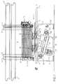
- 1 indicates the conveying line for the plate-shaped material 2 to be stacked in the stacking station in a support and guide structure formed by two series of uprights, each constituted by four elements: front and rear lateral 3, front and rear frontal 4; 5 indicates a pair of oscillating front devices for gripping and retaining the plate-shaped element or tile 2 constituting the bottom of the stack; 6 indicates a pair of fixed rear devices for gripping and retaining the bottom tile; 7 indicates upper framework elements on which the structure of the stacking station is suspended; 8 and 9 indicate two lateral pairs, front and rear respectively, of screw elements, the axis of which is inclined, with regard to the vertical, in the opposite direction with regard to the direction of flow of the tiles 2, in the vertical lateral plane parallel to the vertical longitudinal plane of the line 1 and containing the axes of the same elements, through an angle corresponding to that of inclination of the rectangular thread 10 of the manoeuvring helix fixed on the cylindrical body 11 keyed on a respective shaft 12, 12a, with the latter, advanced towards the
- the plate-shaped body 2, advancing continuously on the conveying line 1 is supported at a level just above the plane defined by the first lower inlet section of the thread 10 of each screw element 8, 9; when the plat-shaped body 2 arrives in the position of coupling which is substantially simultaneous with the inlet portions of the four threads, a detection system (not shown) orders the simultaneous start of the rotation of the two pairs of screw elements 8, 9, bringing about the coupling contact in the absence of relative speed between the upper surfaces of the threads 10 and the corresponding zones of the lower surface of the plate-shaped body 2; during the synchronous rotation of the shafts 12, 12a, the simultaneous advance and lifting of the plate-shaped body takes place until reaching respectively the striker 31 and clamping between the two pairs of front 22 and rear 29 free wheels of the lifting station; in the final section of the rotation of one revolution of the four screw elements, the upper face of the plate-shaped element comes into contact with the bottom of the bottom tile of the stack, thus bringing about the lifting of the same stack by one step corresponding to the thickness of the same
- any inclinations imparted to the axes of the four screw elements 8, 9 in the associated lateral planes, with regard to the vertical, through angular values slightly different to that of inclination of the helix of the thread 10, even affording less advantage, are, however, to be included within the scope of the present invention.
- step-by-step rotation device with mechanical intermitting device could be replaced by an electronic device.
Landscapes
- Engineering & Computer Science (AREA)
- Mechanical Engineering (AREA)
- Attitude Control For Articles On Conveyors (AREA)
- Specific Conveyance Elements (AREA)
Applications Claiming Priority (2)
| Application Number | Priority Date | Filing Date | Title |
|---|---|---|---|
| ITMO940121A IT1269249B (it) | 1994-08-19 | 1994-08-19 | Macchina impilatrice di materiale piastriforme |
| ITMO940121 | 1994-08-19 |
Publications (1)
| Publication Number | Publication Date |
|---|---|
| EP0697355A1 true EP0697355A1 (de) | 1996-02-21 |
Family
ID=11385696
Family Applications (1)
| Application Number | Title | Priority Date | Filing Date |
|---|---|---|---|
| EP95202192A Withdrawn EP0697355A1 (de) | 1994-08-19 | 1995-08-11 | Hubvorrichtung für plattenförmigen Körper, insbesondere für eine Stapelvorrichtung für keramische Fliessen |
Country Status (3)
| Country | Link |
|---|---|
| EP (1) | EP0697355A1 (de) |
| CN (1) | CN1121896A (de) |
| IT (1) | IT1269249B (de) |
Cited By (2)
| Publication number | Priority date | Publication date | Assignee | Title |
|---|---|---|---|---|
| CN102267634A (zh) * | 2011-07-21 | 2011-12-07 | 常熟皮爱尔奇磁性科技有限公司 | 铁氧体磁坯排叠装置 |
| CN117125492A (zh) * | 2023-10-27 | 2023-11-28 | 山西雅美德印刷科技有限公司 | 一种平面印刷用成品输送装置 |
Families Citing this family (17)
| Publication number | Priority date | Publication date | Assignee | Title |
|---|---|---|---|---|
| CN100590048C (zh) * | 2006-03-28 | 2010-02-17 | 江苏亚威机床股份有限公司 | 一种板料堆垛机 |
| CN101386373B (zh) * | 2007-09-10 | 2011-06-22 | 北新集团建材股份有限公司 | 矿棉吸声板原板的提取控制方法及提取装置 |
| CN101898685B (zh) * | 2010-07-05 | 2012-08-15 | 无锡相川铁龙电子有限公司 | 框形产品自动排料机 |
| JP2013208073A (ja) * | 2012-03-30 | 2013-10-10 | Suzutec Co Ltd | 育苗容器重ね方法および育苗容器重ね装置 |
| CN102756921B (zh) * | 2012-07-10 | 2014-12-03 | 中国科学院宁波材料技术与工程研究所 | 纤维片材的工业机器人自动层叠系统 |
| CN103662845A (zh) * | 2012-09-03 | 2014-03-26 | 扬州市力神吊装设备制造有限公司 | 液压打正台 |
| CN104477443B (zh) * | 2014-12-16 | 2016-12-07 | 淄博正邦知识产权企划有限公司 | 一种应用于瓷砖包装线的全自动分级摞砖设备 |
| CN105016245B (zh) * | 2015-07-30 | 2017-08-01 | 江苏锐升新材料有限公司 | 一种用于地板板材输送的升降平台 |
| ITUA20163368A1 (it) * | 2016-05-12 | 2017-11-12 | Marchesini Group Spa | Dispositivo di stabilizzazione per stabilizzare articoli durante il loro sollevamento e raggruppamento |
| CN106697878A (zh) * | 2017-01-12 | 2017-05-24 | 江苏欧圣木业有限公司 | 用于强化地板端部开槽的位置校正装置 |
| CN109016640B (zh) * | 2018-09-10 | 2024-06-25 | 佛山市三水至丰纸品制造有限公司 | 一种瓦楞纸箱折叠钉箱堆叠一体机 |
| CN114423693B (zh) * | 2019-06-03 | 2024-03-22 | 萨克米伊莫拉机械合作社合作公司 | 用于转移陶瓷加工业的物品的方法和系统 |
| CN111837531A (zh) * | 2020-07-30 | 2020-10-30 | 浙江博仁工贸有限公司 | 播种机的叠加育秧盘自动落盘机构 |
| CN112660488B (zh) * | 2020-12-24 | 2025-02-07 | 中烟物流技术有限责任公司 | 一种条烟叠层机构 |
| CN113148587A (zh) * | 2021-05-22 | 2021-07-23 | 沈阳天通电气有限公司 | 一种片式散热器自动叠片装置及工艺方法 |
| CN113374189A (zh) * | 2021-06-02 | 2021-09-10 | 林弟弟 | 一种徽式建筑屋顶瓦片防风铺设设备 |
| CN117800100B (zh) * | 2024-03-01 | 2024-05-10 | 山东辰榜数控装备有限公司 | 一种数控机床加工板料自动堆放设备 |
Citations (3)
| Publication number | Priority date | Publication date | Assignee | Title |
|---|---|---|---|---|
| US4378938A (en) * | 1979-10-09 | 1983-04-05 | Sweda International, Inc. | Document stacking device |
| IT1172719B (it) | 1983-11-17 | 1987-06-18 | Paolo Francia | Macchina automatica per formare pacchi di piastrelle ceramiche sovrapposte ad elevata velocita' operativa e di ingombro ridotto |
| EP0403956A1 (de) * | 1989-06-17 | 1990-12-27 | SANJO MACHINE WORKS, Ltd. | Apparat zum Stapeln und Fördern |
-
1994
- 1994-08-19 IT ITMO940121A patent/IT1269249B/it active IP Right Grant
-
1995
- 1995-08-11 EP EP95202192A patent/EP0697355A1/de not_active Withdrawn
- 1995-08-18 CN CN95108658.8A patent/CN1121896A/zh active Pending
Patent Citations (3)
| Publication number | Priority date | Publication date | Assignee | Title |
|---|---|---|---|---|
| US4378938A (en) * | 1979-10-09 | 1983-04-05 | Sweda International, Inc. | Document stacking device |
| IT1172719B (it) | 1983-11-17 | 1987-06-18 | Paolo Francia | Macchina automatica per formare pacchi di piastrelle ceramiche sovrapposte ad elevata velocita' operativa e di ingombro ridotto |
| EP0403956A1 (de) * | 1989-06-17 | 1990-12-27 | SANJO MACHINE WORKS, Ltd. | Apparat zum Stapeln und Fördern |
Cited By (4)
| Publication number | Priority date | Publication date | Assignee | Title |
|---|---|---|---|---|
| CN102267634A (zh) * | 2011-07-21 | 2011-12-07 | 常熟皮爱尔奇磁性科技有限公司 | 铁氧体磁坯排叠装置 |
| CN102267634B (zh) * | 2011-07-21 | 2012-11-07 | 常熟皮爱尔奇磁性科技有限公司 | 铁氧体磁坯排叠装置 |
| CN117125492A (zh) * | 2023-10-27 | 2023-11-28 | 山西雅美德印刷科技有限公司 | 一种平面印刷用成品输送装置 |
| CN117125492B (zh) * | 2023-10-27 | 2024-01-02 | 山西雅美德印刷科技有限公司 | 一种平面印刷用成品输送装置 |
Also Published As
| Publication number | Publication date |
|---|---|
| ITMO940121A0 (it) | 1994-08-19 |
| IT1269249B (it) | 1997-03-26 |
| ITMO940121A1 (it) | 1994-11-19 |
| CN1121896A (zh) | 1996-05-08 |
Similar Documents
| Publication | Publication Date | Title |
|---|---|---|
| EP0639517B1 (de) | Verpackungs- und Stapelvorrichtung mit seitlicher Stapelausrichtung | |
| US5135351A (en) | Palletized storage method and apparatus | |
| CN110498083B (zh) | 一种物料自动传送堆叠的装置 | |
| US6210093B1 (en) | Transfer apparatus for a plurality of objects | |
| US6511281B2 (en) | Device for palletizing parcels | |
| ITMO940121A1 (it) | Macchina impilatrice di materiale piastriforme | |
| EP0111953A1 (de) | Vorrichtung zum Einsetzen von Kegeln in eine Schachtel | |
| KR101704554B1 (ko) | 지관 자동 포장 및 적재 장치 | |
| US6390766B1 (en) | Shingle bundle palletizer with improved metering conveyor, pattern conveyor and shuttle conveyor | |
| JPH0639703U (ja) | 包装機械 | |
| US6352148B1 (en) | Device for the alignment of tube segments | |
| US4997339A (en) | Device for stacking trays with articles | |
| EP0778237B1 (de) | Anlage zum Zuführen und Stapeln von streifenförmigem Material, Streifenstapler einsetzbar in einer solchen Anlage | |
| JPH07300226A (ja) | 搬送物の搬送方向変換装置 | |
| JPH012741A (ja) | プレス加工製品の整列方法 | |
| GB2115763A (en) | Storage means for packages | |
| US3516532A (en) | Stacking system for paperboard blanks | |
| JPH0462967B2 (de) | ||
| CN214610337U (zh) | 一种自动化输出的码垛机 | |
| CN219408211U (zh) | 一种直线滑移倒包机构 | |
| CN218859381U (zh) | 一种电商播种墙用自动换筐机构 | |
| CN218318822U (zh) | 一种瓶底检测用输送装置 | |
| JP3375091B2 (ja) | 成形品搬送装置 | |
| EP0143546A1 (de) | Apparat zum Entladen von Förderern | |
| KR950012877B1 (ko) | 자동 적재기 |
Legal Events
| Date | Code | Title | Description |
|---|---|---|---|
| PUAI | Public reference made under article 153(3) epc to a published international application that has entered the european phase |
Free format text: ORIGINAL CODE: 0009012 |
|
| AK | Designated contracting states |
Kind code of ref document: A1 Designated state(s): DE ES GB IT |
|
| AX | Request for extension of the european patent |
Free format text: LT;SI |
|
| DAX | Request for extension of the european patent (deleted) | ||
| RBV | Designated contracting states (corrected) |
Designated state(s): DE ES GB IT |
|
| STAA | Information on the status of an ep patent application or granted ep patent |
Free format text: STATUS: THE APPLICATION IS DEEMED TO BE WITHDRAWN |
|
| 18D | Application deemed to be withdrawn |
Effective date: 19960822 |