EP0697364B1 - Anneau de levage pour la prise latérale de charges - Google Patents
Anneau de levage pour la prise latérale de charges Download PDFInfo
- Publication number
- EP0697364B1 EP0697364B1 EP95401901A EP95401901A EP0697364B1 EP 0697364 B1 EP0697364 B1 EP 0697364B1 EP 95401901 A EP95401901 A EP 95401901A EP 95401901 A EP95401901 A EP 95401901A EP 0697364 B1 EP0697364 B1 EP 0697364B1
- Authority
- EP
- European Patent Office
- Prior art keywords
- ring
- collar
- ring according
- intermediate member
- load
- Prior art date
- Legal status (The legal status is an assumption and is not a legal conclusion. Google has not performed a legal analysis and makes no representation as to the accuracy of the status listed.)
- Expired - Lifetime
Links
- 238000004026 adhesive bonding Methods 0.000 claims description 2
- 230000002093 peripheral effect Effects 0.000 claims 1
- 230000006378 damage Effects 0.000 description 2
- 230000004048 modification Effects 0.000 description 2
- 238000012986 modification Methods 0.000 description 2
- 238000007792 addition Methods 0.000 description 1
- 230000003467 diminishing effect Effects 0.000 description 1
- 239000003292 glue Substances 0.000 description 1
- 238000010438 heat treatment Methods 0.000 description 1
- 238000007747 plating Methods 0.000 description 1
- 238000011282 treatment Methods 0.000 description 1
Images
Classifications
-
- B—PERFORMING OPERATIONS; TRANSPORTING
- B66—HOISTING; LIFTING; HAULING
- B66C—CRANES; LOAD-ENGAGING ELEMENTS OR DEVICES FOR CRANES, CAPSTANS, WINCHES, OR TACKLES
- B66C1/00—Load-engaging elements or devices attached to lifting or lowering gear of cranes or adapted for connection therewith for transmitting lifting forces to articles or groups of articles
- B66C1/10—Load-engaging elements or devices attached to lifting or lowering gear of cranes or adapted for connection therewith for transmitting lifting forces to articles or groups of articles by mechanical means
- B66C1/62—Load-engaging elements or devices attached to lifting or lowering gear of cranes or adapted for connection therewith for transmitting lifting forces to articles or groups of articles by mechanical means comprising article-engaging members of a shape complementary to that of the articles to be handled
- B66C1/66—Load-engaging elements or devices attached to lifting or lowering gear of cranes or adapted for connection therewith for transmitting lifting forces to articles or groups of articles by mechanical means comprising article-engaging members of a shape complementary to that of the articles to be handled for engaging holes, recesses, or abutments on articles specially provided for facilitating handling thereof
-
- Y—GENERAL TAGGING OF NEW TECHNOLOGICAL DEVELOPMENTS; GENERAL TAGGING OF CROSS-SECTIONAL TECHNOLOGIES SPANNING OVER SEVERAL SECTIONS OF THE IPC; TECHNICAL SUBJECTS COVERED BY FORMER USPC CROSS-REFERENCE ART COLLECTIONS [XRACs] AND DIGESTS
- Y10—TECHNICAL SUBJECTS COVERED BY FORMER USPC
- Y10T—TECHNICAL SUBJECTS COVERED BY FORMER US CLASSIFICATION
- Y10T403/00—Joints and connections
- Y10T403/32—Articulated members
- Y10T403/32114—Articulated members including static joint
- Y10T403/32213—Articulate joint is a swivel
Definitions
- the subject of the present invention is a ring lifting device for handling a load while fixing in tapped holes thereof, even if these holes are arranged on the side of the load.
- lifting ring In order to allow easy grip of the load from slings, lifting ring, screwed in the tapped hole, is hinged for use in all directions.
- lifting rings which are designed to be removable which has for advantage, in the event of wear or breakage of one of the elements to replace this element see EP-A-365 430 corresponding to the preamble of claim 1.
- the disadvantage, however, of the removable nature of this lifting ring is that one or more essential elements of the ring may then have been disassembled and, without this being apparent for user, replaced with inappropriate items or lower quality.
- the user of a ring lifting like this can therefore always fear that without knowing it, the ring has undergone a modification diminishing the performance for which it is announced by the manufacturer and therefore reducing safety.
- this invention proposes, on the contrary, a lifting ring which is not removable, except to subject it to particular treatments then leaving traces apparent, and which therefore allows use in safely within the limits announced by the manufacturer.
- the ring of lifting includes a stepped threaded axis on which is screwed and blocked an attached base, preferably by gluing, a forged and monobloc crosspiece swiveling freely on the axis while being maintained between the two wings formed by the internal face of the base and from below the head of the axle.
- On the end pins of the crossmember are mounted for freely rotate the ends of the parallel branches of a shackle.
- the invention proposes an arrangement which makes the self-locking rod.
- the shackle branch has on its outside face a housing intended to receive the rod and whose upper wall is inclined by about 25 °. If the shackle branch is subjected to a force of traction towards the outside, the inclined wall guides the relative movement of entry of the rod in the housing from where this one cannot go out any more. The result of forces which are then applied to the rod is directed towards inside the throat and therefore acts to maintain the rod inside the throat.
- the rod being of circular section, it does not exercise any cutting on the trunnion, especially since due to its self-centering it acts on its entire periphery so that the value of "unbuttoning" the end of the journal will be at least 2.5 times the maximum load of use of the ring, thus leaving a large safety margin.
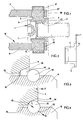
- a non-removable lifting ring which includes a stepped axis 1 on the threaded body 2 from which is screwed a threaded support base 3.
- a cross piece 4 forged and monobloc is mounted for spin freely while being held in between wings formed on the one hand by the internal face 5 of the base 3 and, on the other hand, from below 6 of the head 7 of axis 1.
- the base 3 Since the base 3 is not removable, in normal conditions, it is blocked by bonding to body 2 so that disassembly does not would be possible only by heating at high temperature (over 250 ° C) to neutralize the glue or by destruction which, in either case, does not would not fail to leave visible traces.
- maintaining the branch 9 on the pin 8 is provided by a rod 11, of section circular, which is partially engaged in a groove 12 with semicircular section formed in the periphery pin 8.
- the opening 13 of the branch 9 which is crossed by the pin 8 is continues with a housing 14 delimited by a short wall 15 inclined at an angle of approximately 45 ° which continues with a wall 16 elongated with an inclination of around 25 °.
- the slight tilt mentioned above of the outer face 17 of the base 3 ensures a wear range of this in case of intensive use of the lifting eye, thereby improving the longevity of the ring.
Landscapes
- Engineering & Computer Science (AREA)
- Mechanical Engineering (AREA)
- Hooks, Suction Cups, And Attachment By Adhesive Means (AREA)
- Load-Engaging Elements For Cranes (AREA)
- Emergency Lowering Means (AREA)
Description
- possibilité d'un plaquage maximal de l'embase sur la paroi de la charge ;
- réalisation d'une plage d'usure en cas d'usage intensif de l'anneau ;
- portée de la partie filetée de l'axe par l'embase jusqu'à une limite maximale.
Claims (7)
- Anneau pour le levage de charge, comprenant un axe (1) qui présente un corps fileté (2) destiné à se visser dans un trou taraudé de la charge à manipuler et une tête (7), une pièce intermédiaire (4) forgée et monobloc qui est montée pour tourner sur 360° autour de l'axe (1) et une manille (10) pivotant sur 360° autour de tourillons (8,8') de la pièce intermédiaire (4), caractérisé en ce qu'une embase d'appui taraudée (3) est vissée sur le corps (2) et est bloquée sur celui-ci, la dite pièce intermédiaire (4) tournant autour de l'embase (3) en étant maintenue axialement entre des parties saillantes en regard (5,6) de l'embase (3) et de la tête (7).
- Anneau selon la revendication 1, caractérisé en ce que le blocage de l'embase (3) sur le corps (2) est obtenu par collage.
- Anneau selon la revendication 1 ou la revendication 2, caractérisé en ce que la face (17) de l'embase (3) destinée à s'appliquer contre la charge à manipuler présente une légère inclinaison vers l'intérieur, d'un angle d'environ 1°.
- Anneau selon l'une quelconque des revendications 1 à 3, caractérisé en ce que le maintien de chaque branche (9,9') de la manille (10) sur le tourillon correspondant (8,8') de la pièce intermédiaire (4) est assuré par un jonc (11) engagé dans une gorge périphérique (12) du dit tourillon (8,8').
- Anneau selon la revendication 4, caractérisé en ce que la face extérieure de la dite branche (9,9') présente, au voisinage de son ouverture (13) traversée par le tourillon (8,8'), un logement (14) dans lequel vient se centrer le dit jonc (11) lorsqu'une traction est appliquée sensiblement perpendiculairement à la dite branche (9,9').
- Anneau selon la revendication 5, caractérisé en ce que le dit logement (14) présente une paroi (16) inclinée d'environ 25°, servant de guidage pour le jonc (11) et transmettant à celui-ci un effort dans une direction tendant à maintenir le jonc (11) dans sa gorge (12).
- Anneau selon l'une quelconque des revendications 4 à 6, caractérisé en ce que le dit jonc (11) est de section circulaire.
Applications Claiming Priority (2)
| Application Number | Priority Date | Filing Date | Title |
|---|---|---|---|
| FR9410100A FR2723770B1 (fr) | 1994-08-18 | 1994-08-18 | Anneau de levage pour la prise laterale de charges |
| FR9410100 | 1994-08-18 |
Publications (2)
| Publication Number | Publication Date |
|---|---|
| EP0697364A1 EP0697364A1 (fr) | 1996-02-21 |
| EP0697364B1 true EP0697364B1 (fr) | 2000-04-26 |
Family
ID=9466361
Family Applications (1)
| Application Number | Title | Priority Date | Filing Date |
|---|---|---|---|
| EP95401901A Expired - Lifetime EP0697364B1 (fr) | 1994-08-18 | 1995-08-17 | Anneau de levage pour la prise latérale de charges |
Country Status (7)
| Country | Link |
|---|---|
| US (1) | US5580110A (fr) |
| EP (1) | EP0697364B1 (fr) |
| JP (1) | JPH0891766A (fr) |
| CA (1) | CA2155798C (fr) |
| DE (1) | DE69516469T2 (fr) |
| ES (1) | ES2147826T3 (fr) |
| FR (1) | FR2723770B1 (fr) |
Families Citing this family (5)
| Publication number | Priority date | Publication date | Assignee | Title |
|---|---|---|---|---|
| DE69927493T2 (de) * | 1999-07-09 | 2006-06-22 | S.H.B.L. | Wirbelöse zum Heben von Lasten |
| US7114872B2 (en) | 2001-04-11 | 2006-10-03 | Cbc Industries, Inc. | Wrenchless hoist ring mounting |
| FR2911591B1 (fr) * | 2007-01-23 | 2009-04-17 | Forges De L Eminee Sa | Anneau de levage pour la prise de charges lourdes. |
| EP2880334B1 (fr) * | 2012-07-31 | 2016-06-08 | Pewag Austria GmbH | Anneau à écrou |
| LU92243B1 (fr) | 2013-07-08 | 2015-01-09 | Intelprop Sa | Anneau de levage |
Family Cites Families (8)
| Publication number | Priority date | Publication date | Assignee | Title |
|---|---|---|---|---|
| US3297293A (en) * | 1965-01-13 | 1967-01-10 | American Drill Bushing Company | Fastening device |
| US4558979A (en) * | 1981-09-28 | 1985-12-17 | Andrews Gary E | Fastening device |
| DE3435714C2 (de) * | 1984-09-25 | 1986-11-06 | Rud-Kettenfabrik Rieger & Dietz Gmbh U. Co, 7080 Aalen | Anschlußvorrichtung |
| US4641986A (en) * | 1985-08-30 | 1987-02-10 | Cbc Industries, Inc. | Multi-position eyebolt |
| US4705422A (en) * | 1986-08-08 | 1987-11-10 | Cbc Industries, Inc. | Multi-position fixture |
| FR2638150B1 (fr) * | 1988-10-21 | 1990-12-28 | Lecourt Marc | Anneau de levage perfectionne pour la prise laterale de charges lourdes |
| DE68917320T2 (de) * | 1989-03-15 | 1994-12-08 | Lars Enebyberg Fredriksson | Schwenkbare kupplungsanordnung. |
| US5352056A (en) * | 1992-11-30 | 1994-10-04 | The Crosby Group, Inc. | Hoist ring with self-lock retaining ring |
-
1994
- 1994-08-18 FR FR9410100A patent/FR2723770B1/fr not_active Expired - Lifetime
-
1995
- 1995-08-10 CA CA002155798A patent/CA2155798C/fr not_active Expired - Lifetime
- 1995-08-17 JP JP7209407A patent/JPH0891766A/ja active Pending
- 1995-08-17 DE DE69516469T patent/DE69516469T2/de not_active Expired - Lifetime
- 1995-08-17 EP EP95401901A patent/EP0697364B1/fr not_active Expired - Lifetime
- 1995-08-17 US US08/516,469 patent/US5580110A/en not_active Expired - Fee Related
- 1995-08-17 ES ES95401901T patent/ES2147826T3/es not_active Expired - Lifetime
Also Published As
| Publication number | Publication date |
|---|---|
| CA2155798C (fr) | 1998-06-09 |
| FR2723770B1 (fr) | 1996-10-18 |
| US5580110A (en) | 1996-12-03 |
| EP0697364A1 (fr) | 1996-02-21 |
| DE69516469T2 (de) | 2000-12-14 |
| CA2155798A1 (fr) | 1996-02-19 |
| FR2723770A1 (fr) | 1996-02-23 |
| ES2147826T3 (es) | 2000-10-01 |
| JPH0891766A (ja) | 1996-04-09 |
| DE69516469D1 (de) | 2000-05-31 |
Similar Documents
| Publication | Publication Date | Title |
|---|---|---|
| EP0211778B1 (fr) | Raccord à griffes | |
| EP1073373B1 (fr) | Implant osseux comprenant un dispositif de fixation reversible | |
| EP0434825B1 (fr) | Ecrou rapide | |
| EP2338776B1 (fr) | Jeu de direction de cycle à goupille et cycle comportant un tel jeu de direction | |
| CA3011509C (fr) | Anneau de levage pivotant pour le levage de charges | |
| FR2529489A1 (fr) | Embrayage a friction monte par rivetage des ressorts a lames avec le plateau de pression, et procede de rivetage correspondant | |
| EP0697364B1 (fr) | Anneau de levage pour la prise latérale de charges | |
| FR2797208A1 (fr) | Element antivibrations pourvu d'une surete d'arrachement | |
| EP0571294B1 (fr) | Collier de serrage à vis | |
| EP0496702A1 (fr) | Dispositif antidérapant pour roue de véhicule | |
| FR2489902A1 (fr) | Element de liaison | |
| FR2686130A1 (fr) | Dispositif de fixation a butee-guide axiale escamotable. | |
| EP1164106B1 (fr) | Anneau de levage | |
| EP3617543B1 (fr) | Disque arriere d'une pile de disques en carbone de frein d'aeronef equipe de plots, et frein faisant application | |
| FR2475911A1 (fr) | Baton de ski de longueur variable | |
| FR2638150A1 (fr) | Anneau de levage perfectionne pour la prise laterale de charges lourdes | |
| EP0315722A1 (fr) | Fermoir | |
| FR2754022A1 (fr) | Bloqueur de rotation pour un outil, monte rotatif, d'un instrument de travail | |
| FR2622768A1 (fr) | Ensemble pour fixer une ligne a une extremite de canne a peche | |
| FR2757646A1 (fr) | Charniere elastique de lunettes | |
| EP3019430B1 (fr) | Anneau de levage | |
| EP0085631A1 (fr) | Perfectionnements apportés aux crochets à verrouillage | |
| FR2620179A1 (fr) | Dispositif de liaison a vis entre deux pieces avec possibilite de reglage de l'ecartement entre celles-ci | |
| FR2680361A1 (fr) | Elingue a usage unique pour le fardelage et la manipulation d'elements allonges. | |
| EP1254391A1 (fr) | Manchon de fixation pour cables optiques |
Legal Events
| Date | Code | Title | Description |
|---|---|---|---|
| PUAI | Public reference made under article 153(3) epc to a published international application that has entered the european phase |
Free format text: ORIGINAL CODE: 0009012 |
|
| AK | Designated contracting states |
Kind code of ref document: A1 Designated state(s): BE DE ES GB IT LU SE |
|
| 17P | Request for examination filed |
Effective date: 19960816 |
|
| GRAG | Despatch of communication of intention to grant |
Free format text: ORIGINAL CODE: EPIDOS AGRA |
|
| GRAG | Despatch of communication of intention to grant |
Free format text: ORIGINAL CODE: EPIDOS AGRA |
|
| GRAH | Despatch of communication of intention to grant a patent |
Free format text: ORIGINAL CODE: EPIDOS IGRA |
|
| 17Q | First examination report despatched |
Effective date: 19990929 |
|
| GRAH | Despatch of communication of intention to grant a patent |
Free format text: ORIGINAL CODE: EPIDOS IGRA |
|
| GRAA | (expected) grant |
Free format text: ORIGINAL CODE: 0009210 |
|
| AK | Designated contracting states |
Kind code of ref document: B1 Designated state(s): BE DE ES GB IT LU SE |
|
| REF | Corresponds to: |
Ref document number: 69516469 Country of ref document: DE Date of ref document: 20000531 |
|
| ITF | It: translation for a ep patent filed | ||
| GBT | Gb: translation of ep patent filed (gb section 77(6)(a)/1977) |
Effective date: 20000727 |
|
| REG | Reference to a national code |
Ref country code: ES Ref legal event code: FG2A Ref document number: 2147826 Country of ref document: ES Kind code of ref document: T3 |
|
| PLBE | No opposition filed within time limit |
Free format text: ORIGINAL CODE: 0009261 |
|
| STAA | Information on the status of an ep patent application or granted ep patent |
Free format text: STATUS: NO OPPOSITION FILED WITHIN TIME LIMIT |
|
| 26N | No opposition filed | ||
| REG | Reference to a national code |
Ref country code: GB Ref legal event code: IF02 |
|
| PG25 | Lapsed in a contracting state [announced via postgrant information from national office to epo] |
Ref country code: DE Free format text: LAPSE BECAUSE OF NON-PAYMENT OF DUE FEES Effective date: 20070301 |
|
| PGFP | Annual fee paid to national office [announced via postgrant information from national office to epo] |
Ref country code: GB Payment date: 20140617 Year of fee payment: 20 |
|
| PGFP | Annual fee paid to national office [announced via postgrant information from national office to epo] |
Ref country code: LU Payment date: 20140604 Year of fee payment: 20 |
|
| PGFP | Annual fee paid to national office [announced via postgrant information from national office to epo] |
Ref country code: BE Payment date: 20140618 Year of fee payment: 20 Ref country code: DE Payment date: 20140617 Year of fee payment: 20 |
|
| PGFP | Annual fee paid to national office [announced via postgrant information from national office to epo] |
Ref country code: ES Payment date: 20140618 Year of fee payment: 20 Ref country code: SE Payment date: 20140827 Year of fee payment: 20 |
|
| PGFP | Annual fee paid to national office [announced via postgrant information from national office to epo] |
Ref country code: IT Payment date: 20140828 Year of fee payment: 20 |
|
| REG | Reference to a national code |
Ref country code: DE Ref legal event code: R071 Ref document number: 69516469 Country of ref document: DE |
|
| REG | Reference to a national code |
Ref country code: GB Ref legal event code: PE20 Expiry date: 20150816 |
|
| REG | Reference to a national code |
Ref country code: SE Ref legal event code: EUG |
|
| PG25 | Lapsed in a contracting state [announced via postgrant information from national office to epo] |
Ref country code: GB Free format text: LAPSE BECAUSE OF EXPIRATION OF PROTECTION Effective date: 20150816 |
|
| REG | Reference to a national code |
Ref country code: ES Ref legal event code: FD2A Effective date: 20151126 |
|
| PG25 | Lapsed in a contracting state [announced via postgrant information from national office to epo] |
Ref country code: ES Free format text: LAPSE BECAUSE OF EXPIRATION OF PROTECTION Effective date: 20150818 |