EP0697367A1 - Plate-forme de levage à ciseaux - Google Patents
Plate-forme de levage à ciseaux Download PDFInfo
- Publication number
- EP0697367A1 EP0697367A1 EP95109613A EP95109613A EP0697367A1 EP 0697367 A1 EP0697367 A1 EP 0697367A1 EP 95109613 A EP95109613 A EP 95109613A EP 95109613 A EP95109613 A EP 95109613A EP 0697367 A1 EP0697367 A1 EP 0697367A1
- Authority
- EP
- European Patent Office
- Prior art keywords
- lever
- spreading
- arm
- scissor
- pressure medium
- Prior art date
- Legal status (The legal status is an assumption and is not a legal conclusion. Google has not performed a legal analysis and makes no representation as to the accuracy of the status listed.)
- Withdrawn
Links
- 230000007480 spreading Effects 0.000 claims description 48
- 230000007246 mechanism Effects 0.000 claims description 11
- XEEYBQQBJWHFJM-UHFFFAOYSA-N Iron Chemical compound [Fe] XEEYBQQBJWHFJM-UHFFFAOYSA-N 0.000 claims 2
- 229910052742 iron Inorganic materials 0.000 claims 1
- 241000219098 Parthenocissus Species 0.000 description 2
- 235000000396 iron Nutrition 0.000 description 2
- 238000000034 method Methods 0.000 description 2
- 230000008569 process Effects 0.000 description 2
- 230000009471 action Effects 0.000 description 1
- 230000000694 effects Effects 0.000 description 1
- 238000004519 manufacturing process Methods 0.000 description 1
- 230000002028 premature Effects 0.000 description 1
Images

Classifications
-
- B—PERFORMING OPERATIONS; TRANSPORTING
- B66—HOISTING; LIFTING; HAULING
- B66F—HOISTING, LIFTING, HAULING OR PUSHING, NOT OTHERWISE PROVIDED FOR, e.g. DEVICES WHICH APPLY A LIFTING OR PUSHING FORCE DIRECTLY TO THE SURFACE OF A LOAD
- B66F7/00—Lifting frames, e.g. for lifting vehicles; Platform lifts
- B66F7/06—Lifting frames, e.g. for lifting vehicles; Platform lifts with platforms supported by levers for vertical movement
- B66F7/08—Lifting frames, e.g. for lifting vehicles; Platform lifts with platforms supported by levers for vertical movement hydraulically or pneumatically operated
-
- B—PERFORMING OPERATIONS; TRANSPORTING
- B66—HOISTING; LIFTING; HAULING
- B66F—HOISTING, LIFTING, HAULING OR PUSHING, NOT OTHERWISE PROVIDED FOR, e.g. DEVICES WHICH APPLY A LIFTING OR PUSHING FORCE DIRECTLY TO THE SURFACE OF A LOAD
- B66F7/00—Lifting frames, e.g. for lifting vehicles; Platform lifts
- B66F7/06—Lifting frames, e.g. for lifting vehicles; Platform lifts with platforms supported by levers for vertical movement
- B66F7/065—Scissor linkages, i.e. X-configuration
Definitions
- the invention relates to a scissor lift for motor vehicles in particular, consisting of a scissor linkage, the spars supported on fixed floor rails are pivotally connected by a central hinge pin, from at least one horizontal support element for the loads to be lifted, which is articulated with the upper ends of the two spars is connected, from a pressure medium cylinder acting on one of the spars for the lifting and Lowering movements of the support element and from a spreading mechanism with a spreading lever which can be actuated by the pressure medium cylinder and which raises the completely retracted bars to an intermediate position predetermined by a stop.
- Scissor lifts should have the lowest possible height when collapsed in order to facilitate the positioning of the loads to be lifted. This applies in particular to motor vehicle lifts which, in the retracted state, should protrude only as little as possible above the level of the carriageway, in order to enable problem-free access via ramps articulated on the end. Since, in order to achieve the desired low overall height, the scissor bars in the collapsed state lie approximately parallel to one another in the same plane and only at a very small angle of inclination to the central axis of the pressure medium cylinder, which results in an unfavorable lever geometry for the initial phase of each stroke movement with an unnecessarily high expenditure of force and stress of the components involved in the lifting process.
- a spreading mechanism for a generic lifting platform which has a pivoted lever which is articulated on a scissor arm outside the scissor joint pin and on the upper arm of which the piston rod of the pressure medium cylinder is articulated, the articulated axis of this piston rod articulation being moved around a predetermined position in the retracted state Value extends above the articulation axis of the spreading lever on the scissor arm. Because of this difference in height of the two joint axes leads the spreading lever at the initial extension of the piston rod from the pressure medium cylinder pivots about its articulation axis, the other free arm of this spreading lever being supported by means of a lower attachment on a pressure piece which is mounted on the other scissor arm. The pivoting movement of the spreading arm is terminated by the free arm bearing against a stop on the support beam, whereupon the further lifting operation takes place in a conventional manner due to the stable fixing of the pivot arm.
- a scissor lift which, in order to achieve the smallest possible height with retracted scissor bars, has a spreading mechanism which largely corresponds to the spreading mechanism discussed above.
- a pivotable spreading lever is articulated to the single pressure medium cylinder, this spreading lever being pivotably mounted on one scissor arm and supported on the other scissor arm until a predetermined intermediate height is reached.
- a nose formed on the spreading lever engages with a stop element fastened to the scissor arm, whereby the position of the spreading lever is fixed and the further lifting operation is carried out in a conventional manner directly by the pressure medium cylinder.
- a lifting device for lifting the vehicle bodies from the chassis of a truck in which, in order to facilitate the initial phase, the housing of the pressure medium cylinder engages on an arm of an expansion lever articulated in the axis of rotation of two scissor bars.
- the second arm of this spreading lever is supported on a roller arranged in the floor rail until a predetermined intermediate position is reached.
- a disadvantage of the known spreading mechanisms of lifting platforms is that the spreading levers used in each case, as well as their support and stop elements, are arranged in the central region of the scissor bars, in that there are unfavorable spaces. Accordingly, the size of the respective spreading lever is limited, which leads to relatively high mechanical loads and premature wear of the components involved in the initial stroke. Due to the limited space, the assembly and disassembly of the expansion device is relatively complex.
- the object of the invention is to provide a scissor lift with an additional spreading mechanism for the initial phase of each lifting operation, in which this spreading mechanism is more favorably positioned and enables a lever geometry that is improved compared to known mechanisms.
- the two-arm spreading lever engages one arm directly on the horizontal support element during the initial phase of each lifting movement or the end phase of each lowering movement.
- the spreading lever is articulated in its central region to a foot which is expediently fastened to the end of a floor rail and has a cross plate or the like as a stop for the spreading lever.
- the housing of the pressure medium cylinder is articulated on the lower arm of the expansion lever and at least at the end of its upper arm a roller mounted, which runs until the intermediate position is reached on a suitable guide surface on the underside of the support element.
- the spreading lever consists of two uniformly shaped flat irons, each of which is articulated on a side cheek of the fixed foot via a separate pin.
- the upper arms of the two flat bars are connected to each other by a common axis and each end carries a roller.
- the lifting platform according to the invention is advantageous compared to known designs with a centrally arranged spreading device, because the spreading lever is freely accessible and its position is in no way influenced by the basic elements of the lifting platform, in particular by the scissor bars moving against each other. This results in a free choice of the optimal dimensions and shapes of these spreading levers, particularly with a view to achieving a reduced lifting speed or a creep speed, which is achieved in conventional systems by means of special lowering brake valves in the hydraulic system.
- the spreading lever designed according to the invention with the rollers or sliding blocks is easier and cheaper to manufacture compared to the spreading mechanisms arranged in the central region of the scissor bars with partially milled cam tracks.
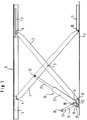
- the scissor lift shown in side view in FIG. 1 contains two scissor bars 1, 2, which are pivotally connected to one another in their central region via a central hinge pin 3.
- a horizontal support element 5 is articulated via a pin 4 in the form of a U-shaped support rail, which on the underside of its central web carries a covering 6 on the left end part in FIG. 1 and a guide rail 7 on the right end part.
- a roller 8 or a sliding block mounted on the free end of the second scissor bar 2 runs in this guide rail 7.
- the two scissor bars 1, 2 are supported on a possibly multi-part base rail 9, the first scissor bar 1 is guided at its lower end by means of a roller 10 in a rail 11.
- the lower end of the second scissor bar 2 is articulated via a hinge pin 12 to a foot 13 which is firmly connected to the bottom rail 9.
- a two-armed angled spreading lever 15 is pivotally mounted about a pin 16, which carries a roller 18 at the end of its upper, longer arm 17.
- the housing 21 of a pressure medium cylinder 20 is articulated via a pivot pin 22.
- the piston rod 23 of the pressure medium cylinder 20 engages via a hinge pin 24 on the upper part of the scissor bar 1 in FIG. 1 between the central hinge pin 3 and the hinge pin 4.
- the lower arm 19 of the spreading lever 15 is supported on a stop plate 25 which is fastened to the foot 13 (cf. FIGS. 2, 3).
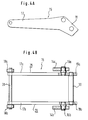
- the spreading lever 15 shown in FIGS. 4A, 4B consists of two flat irons 28, 29 of the shape shown in FIG. 4A, each of which has a pivot pin 16a, 16b for mounting in a side cheek 14a, 14b of the foot 13.
- the two shorter arms 19a, 19b are connected to one another by a stable bolt 30, on which the housing 21 of the pressure medium cylinder 20 engages via a pressure bearing (not shown).
- the two longer arms 17a, 17b are connected to one another by a cross bolt 31, at each end of which a roller 18a, 18b is mounted.
- the piston rod 23 of the pressure medium cylinder 20 also extends in the initial phase of the lifting movement and exerts a lifting force which increases with the spreading angle on the scissor bars 1, 2.
- the spreading lever 15 engages at one end of the mounting rail 5 until the intermediate position shown in FIG. 3 is reached, the parallel position of the mounting rail 5 is always maintained by the action of the scissor linkage.
- Particularly useful in the scissor lift shown is the fact that the spreading device according to the invention also comes into effect in the final phase of a lowering movement, this last part of the lowering movement taking place in what is known as the creeper gear, in which the load transmitted from the mounting rail to the spreading lever 2 pivoted into the position shown in FIG. 2 and at the same time presses the cylinder housing 21 into its starting position according to FIG. 2 via the short spreading arm 19.
- the valves in the hydraulic system previously required for such a creeper can therefore be dispensed with.
- the spreading lever 15 can also have another suitable shape and instead of the rollers 18 at the free end of its arm part 17, for. B. have sliding blocks or other suitable thrust pieces.
Landscapes
- Life Sciences & Earth Sciences (AREA)
- Engineering & Computer Science (AREA)
- Geology (AREA)
- Mechanical Engineering (AREA)
- Structural Engineering (AREA)
- Forklifts And Lifting Vehicles (AREA)
- Glass Compositions (AREA)
- Insulated Conductors (AREA)
- Sanitary Device For Flush Toilet (AREA)
Applications Claiming Priority (2)
| Application Number | Priority Date | Filing Date | Title |
|---|---|---|---|
| DE9413187U DE9413187U1 (de) | 1994-08-16 | 1994-08-16 | Scheren-Hebebühne |
| DE9413187U | 1994-08-16 |
Publications (1)
| Publication Number | Publication Date |
|---|---|
| EP0697367A1 true EP0697367A1 (fr) | 1996-02-21 |
Family
ID=6912437
Family Applications (1)
| Application Number | Title | Priority Date | Filing Date |
|---|---|---|---|
| EP95109613A Withdrawn EP0697367A1 (fr) | 1994-08-16 | 1995-06-21 | Plate-forme de levage à ciseaux |
Country Status (2)
| Country | Link |
|---|---|
| EP (1) | EP0697367A1 (fr) |
| DE (1) | DE9413187U1 (fr) |
Cited By (7)
| Publication number | Priority date | Publication date | Assignee | Title |
|---|---|---|---|---|
| EP0937677A3 (fr) * | 1998-02-21 | 2002-12-11 | The UK Lift Company Ltd. | Dispositifs de levage à ciseaux |
| EP1731125A1 (fr) * | 2005-06-09 | 2006-12-13 | Sanyo Inc. | Dispositif auxiliaire de levage pour lit levable |
| CN105016073A (zh) * | 2015-07-02 | 2015-11-04 | 洛阳理工学院 | 一种具有自润滑关节的升降移位装置 |
| DE202015003870U1 (de) | 2015-06-03 | 2016-07-06 | Andreas Wilhelm Mummenhoff | Hubvorrichtung zum Heben und Senken von Kraftfahrzeugen |
| CN109399499A (zh) * | 2018-11-07 | 2019-03-01 | 农业部南京农业机械化研究所 | 一种剪叉式节能升降装置 |
| CN110228330A (zh) * | 2019-06-06 | 2019-09-13 | 东北农业大学 | 一种轮距无级调节装置 |
| CN114789969A (zh) * | 2021-01-25 | 2022-07-26 | 南京以太通信技术有限公司 | 一种升降机构 |
Families Citing this family (4)
| Publication number | Priority date | Publication date | Assignee | Title |
|---|---|---|---|---|
| GB0719106D0 (en) * | 2007-10-02 | 2007-11-14 | Uk Lift Company The Ltd | Scissor lift |
| CN110255372B (zh) * | 2019-06-02 | 2024-03-22 | 江苏三工建材科技有限公司 | 一种插拔钎设备用过桥装置 |
| CN110294054B (zh) * | 2019-07-23 | 2024-07-19 | 杭州易博特科技有限公司 | 新型电动剪叉举升机构及自动导引运输车 |
| CN110864020A (zh) * | 2019-11-29 | 2020-03-06 | 张炜 | 一种双油缸自动拔销机构 |
Citations (8)
| Publication number | Priority date | Publication date | Assignee | Title |
|---|---|---|---|---|
| US2501001A (en) * | 1947-02-10 | 1950-03-21 | Don A Neely | Linkage mechanism with two lifting phases |
| US2899172A (en) | 1959-08-11 | cresci | ||
| GB915556A (fr) * | 1958-12-06 | 1963-01-16 | Ingo Trepel | |
| US4114854A (en) * | 1977-06-10 | 1978-09-19 | Pac-Craft Products, Inc. | Scissors lift work platform |
| US4890692A (en) * | 1988-12-06 | 1990-01-02 | Jlg Industries, Inc. | Platform elevating apparatus |
| WO1990004565A1 (fr) | 1988-10-25 | 1990-05-03 | Sehlstedt Per Olof | Dispositif permettant de declencher un mouvement de levage dans un appareil de levage |
| FR2673926A1 (fr) * | 1991-03-14 | 1992-09-18 | Duarib Sa | Plate-forme elevatrice a ciseaux. |
| DE9205900U1 (de) | 1992-05-07 | 1992-10-01 | Otto Nußbaum GmbH & Co KG, 7640 Kehl | Hebebühne mit Spreizhebel |
-
1994
- 1994-08-16 DE DE9413187U patent/DE9413187U1/de not_active Expired - Lifetime
-
1995
- 1995-06-21 EP EP95109613A patent/EP0697367A1/fr not_active Withdrawn
Patent Citations (8)
| Publication number | Priority date | Publication date | Assignee | Title |
|---|---|---|---|---|
| US2899172A (en) | 1959-08-11 | cresci | ||
| US2501001A (en) * | 1947-02-10 | 1950-03-21 | Don A Neely | Linkage mechanism with two lifting phases |
| GB915556A (fr) * | 1958-12-06 | 1963-01-16 | Ingo Trepel | |
| US4114854A (en) * | 1977-06-10 | 1978-09-19 | Pac-Craft Products, Inc. | Scissors lift work platform |
| WO1990004565A1 (fr) | 1988-10-25 | 1990-05-03 | Sehlstedt Per Olof | Dispositif permettant de declencher un mouvement de levage dans un appareil de levage |
| US4890692A (en) * | 1988-12-06 | 1990-01-02 | Jlg Industries, Inc. | Platform elevating apparatus |
| FR2673926A1 (fr) * | 1991-03-14 | 1992-09-18 | Duarib Sa | Plate-forme elevatrice a ciseaux. |
| DE9205900U1 (de) | 1992-05-07 | 1992-10-01 | Otto Nußbaum GmbH & Co KG, 7640 Kehl | Hebebühne mit Spreizhebel |
Cited By (8)
| Publication number | Priority date | Publication date | Assignee | Title |
|---|---|---|---|---|
| EP0937677A3 (fr) * | 1998-02-21 | 2002-12-11 | The UK Lift Company Ltd. | Dispositifs de levage à ciseaux |
| EP1731125A1 (fr) * | 2005-06-09 | 2006-12-13 | Sanyo Inc. | Dispositif auxiliaire de levage pour lit levable |
| DE202015003870U1 (de) | 2015-06-03 | 2016-07-06 | Andreas Wilhelm Mummenhoff | Hubvorrichtung zum Heben und Senken von Kraftfahrzeugen |
| CN105016073A (zh) * | 2015-07-02 | 2015-11-04 | 洛阳理工学院 | 一种具有自润滑关节的升降移位装置 |
| CN109399499A (zh) * | 2018-11-07 | 2019-03-01 | 农业部南京农业机械化研究所 | 一种剪叉式节能升降装置 |
| CN109399499B (zh) * | 2018-11-07 | 2024-03-22 | 农业部南京农业机械化研究所 | 一种剪叉式节能升降装置 |
| CN110228330A (zh) * | 2019-06-06 | 2019-09-13 | 东北农业大学 | 一种轮距无级调节装置 |
| CN114789969A (zh) * | 2021-01-25 | 2022-07-26 | 南京以太通信技术有限公司 | 一种升降机构 |
Also Published As
| Publication number | Publication date |
|---|---|
| DE9413187U1 (de) | 1994-10-13 |
Similar Documents
| Publication | Publication Date | Title |
|---|---|---|
| EP2243742B1 (fr) | Plate-forme de levage à ciseaux | |
| DE68904750T2 (de) | Scherenheber fuer fahrzeuge. | |
| EP1122205B1 (fr) | Plate-forme de levage à ciseaux | |
| DE69418792T2 (de) | Arbeitsplattform mit Einzelbalken | |
| DE4430543C2 (de) | Hubvorrichtung | |
| DE3878522T2 (de) | Nivelliervorrichtung fuer an gelenkauslegern angeordnete arbeitsplattformen. | |
| EP1275611B1 (fr) | Table élévatrice à ciseaux | |
| DE19839835A1 (de) | Hebevorrichtung | |
| EP0221911B1 (fr) | Cric | |
| EP2158152A1 (fr) | Dispositif de levage articulé | |
| DE69920783T2 (de) | Krafthebevorrichtung für Fahrzeuge | |
| EP0697367A1 (fr) | Plate-forme de levage à ciseaux | |
| DE2116842A1 (de) | Fahrbarer, zum Aufbau auf Kraftfahrzeuge bestimmter Kran mit drei hydraulisch gesteuerten Hebestufen | |
| EP1375409A1 (fr) | Dispositif de levage à ciseaux pour une installation de convoyage à rouleaux | |
| EP0336927A1 (fr) | Pont de voiture mobile | |
| DE2119316A1 (de) | Aufzug für Fahrzeuge | |
| EP2053010A2 (fr) | Dispositif de verrouillage | |
| EP0009778B1 (fr) | Dispositif pour garer des véhicules sur des plates-formes mobiles | |
| DE3439292C2 (fr) | ||
| DE2843587C2 (de) | Hebevorrichtung mit einer um eine lotrechte Achse drehbaren Plattform für einen Ausleger | |
| EP2534086A1 (fr) | Dispositif d'installation pour plates-formes de levage à parallélogramme | |
| EP0700863B1 (fr) | Plateforme de levage | |
| DE3943425A1 (de) | Hebebuehne insbesondere fuer kraftfahrzeuge | |
| DE69416523T2 (de) | Vorrichtung zum ausrichten beschädigter kraftfahrzeugkarosserien und kraftfahrzeuge | |
| DE2516606A1 (de) | Lastentransportfahrzeug mit einer hebeplattform |
Legal Events
| Date | Code | Title | Description |
|---|---|---|---|
| PUAI | Public reference made under article 153(3) epc to a published international application that has entered the european phase |
Free format text: ORIGINAL CODE: 0009012 |
|
| AK | Designated contracting states |
Kind code of ref document: A1 Designated state(s): DE ES FR GB IT |
|
| 17P | Request for examination filed |
Effective date: 19960816 |
|
| 17Q | First examination report despatched |
Effective date: 19980908 |
|
| STAA | Information on the status of an ep patent application or granted ep patent |
Free format text: STATUS: THE APPLICATION HAS BEEN WITHDRAWN |
|
| 18W | Application withdrawn |
Withdrawal date: 19981023 |