EP0697489B1 - Elément d'appui pour l'isolation acoustique des bruits de chocs - Google Patents
Elément d'appui pour l'isolation acoustique des bruits de chocs Download PDFInfo
- Publication number
- EP0697489B1 EP0697489B1 EP95107649A EP95107649A EP0697489B1 EP 0697489 B1 EP0697489 B1 EP 0697489B1 EP 95107649 A EP95107649 A EP 95107649A EP 95107649 A EP95107649 A EP 95107649A EP 0697489 B1 EP0697489 B1 EP 0697489B1
- Authority
- EP
- European Patent Office
- Prior art keywords
- structural element
- container
- receptacle
- screw
- force
- Prior art date
- Legal status (The legal status is an assumption and is not a legal conclusion. Google has not performed a legal analysis and makes no representation as to the accuracy of the status listed.)
- Expired - Lifetime
Links
- 239000000463 material Substances 0.000 claims abstract description 16
- 229920001971 elastomer Polymers 0.000 claims description 25
- 239000000806 elastomer Substances 0.000 claims description 25
- 239000011178 precast concrete Substances 0.000 claims description 4
- 238000006243 chemical reaction Methods 0.000 claims description 2
- 239000004567 concrete Substances 0.000 abstract description 23
- 229910000831 Steel Inorganic materials 0.000 abstract description 5
- 239000010959 steel Substances 0.000 abstract description 5
- 238000009434 installation Methods 0.000 abstract description 3
- 239000004033 plastic Substances 0.000 abstract description 2
- 229920003023 plastic Polymers 0.000 abstract description 2
- 239000002986 polymer concrete Substances 0.000 abstract description 2
- 230000005540 biological transmission Effects 0.000 description 11
- 238000009413 insulation Methods 0.000 description 8
- 238000010276 construction Methods 0.000 description 7
- 238000004519 manufacturing process Methods 0.000 description 5
- 238000009415 formwork Methods 0.000 description 3
- 239000011810 insulating material Substances 0.000 description 3
- 230000002787 reinforcement Effects 0.000 description 3
- 239000004576 sand Substances 0.000 description 3
- 238000009826 distribution Methods 0.000 description 2
- 238000000034 method Methods 0.000 description 2
- 229920000297 Rayon Polymers 0.000 description 1
- 238000001311 chemical methods and process Methods 0.000 description 1
- 238000009792 diffusion process Methods 0.000 description 1
- 230000000694 effects Effects 0.000 description 1
- 230000005284 excitation Effects 0.000 description 1
- 239000000835 fiber Substances 0.000 description 1
- 239000000945 filler Substances 0.000 description 1
- 230000010006 flight Effects 0.000 description 1
- 239000007788 liquid Substances 0.000 description 1
- NJPPVKZQTLUDBO-UHFFFAOYSA-N novaluron Chemical compound C1=C(Cl)C(OC(F)(F)C(OC(F)(F)F)F)=CC=C1NC(=O)NC(=O)C1=C(F)C=CC=C1F NJPPVKZQTLUDBO-UHFFFAOYSA-N 0.000 description 1
- 238000009417 prefabrication Methods 0.000 description 1
- 230000000717 retained effect Effects 0.000 description 1
- 238000003860 storage Methods 0.000 description 1
- 239000000126 substance Substances 0.000 description 1
- 230000007704 transition Effects 0.000 description 1
- 238000009424 underpinning Methods 0.000 description 1
Images
Classifications
-
- E—FIXED CONSTRUCTIONS
- E04—BUILDING
- E04B—GENERAL BUILDING CONSTRUCTIONS; WALLS, e.g. PARTITIONS; ROOFS; FLOORS; CEILINGS; INSULATION OR OTHER PROTECTION OF BUILDINGS
- E04B1/00—Constructions in general; Structures which are not restricted either to walls, e.g. partitions, or floors or ceilings or roofs
- E04B1/62—Insulation or other protection; Elements or use of specified material therefor
- E04B1/74—Heat, sound or noise insulation, absorption, or reflection; Other building methods affording favourable thermal or acoustical conditions, e.g. accumulating of heat within walls
- E04B1/82—Heat, sound or noise insulation, absorption, or reflection; Other building methods affording favourable thermal or acoustical conditions, e.g. accumulating of heat within walls specifically with respect to sound only
- E04B1/84—Sound-absorbing elements
-
- E—FIXED CONSTRUCTIONS
- E04—BUILDING
- E04F—FINISHING WORK ON BUILDINGS, e.g. STAIRS, FLOORS
- E04F11/00—Stairways, ramps, or like structures; Balustrades; Handrails
- E04F11/02—Stairways; Layouts thereof
- E04F11/022—Stairways; Layouts thereof characterised by the supporting structure
-
- E—FIXED CONSTRUCTIONS
- E04—BUILDING
- E04B—GENERAL BUILDING CONSTRUCTIONS; WALLS, e.g. PARTITIONS; ROOFS; FLOORS; CEILINGS; INSULATION OR OTHER PROTECTION OF BUILDINGS
- E04B1/00—Constructions in general; Structures which are not restricted either to walls, e.g. partitions, or floors or ceilings or roofs
- E04B1/62—Insulation or other protection; Elements or use of specified material therefor
- E04B1/74—Heat, sound or noise insulation, absorption, or reflection; Other building methods affording favourable thermal or acoustical conditions, e.g. accumulating of heat within walls
- E04B1/82—Heat, sound or noise insulation, absorption, or reflection; Other building methods affording favourable thermal or acoustical conditions, e.g. accumulating of heat within walls specifically with respect to sound only
- E04B2001/8254—Soundproof supporting of building elements, e.g. stairs, floor slabs or beams, on a structure
Definitions
- the invention relates to a device for impact sound insulation vertical support of a first component, in particular a precast element, on one adjacent second component, with a receptacle in one of the components and with a shear force mandrel, that cooperates with the recording at one end and with its other end towards the other Device protrudes, in the support area between Intake and transverse force mandrel an impact sound absorbing, elastic layer is arranged.
- Such a device is e.g. from the DE-GBM 78 27 042 known. It is used there by one prefabricated stair run made of running boards and side, made of profiled steel under stairs acoustic decoupling on the inner wall of a To house. The shear force mandrel is fixed connected to the steps and the recording is in the house wall as a sleeve with a sound-absorbing lining integrated.
- the production of the stepped fold must therefore be carried out in particular be carried out with high precision as a subsequent adjustment is not possible.
- step folds requires both an additional one in the flight of stairs and on the platform side Stirrup reinforcement.
- the component prepared in this way is used on the construction site with projecting shear force mandrels then with a Crane positioned. At this point they are Stair landings as components on which the stair run should be supported, at least as far as prepared, that on them recordings for those protruding from the stairs Shear force arbors are present.
- the recordings have an elastomer layer on the underside on which the shear force mandrels rest and about the no vibrations between the shear force mandrel and recording can be transferred. So that supports the flight of stairs over the ones in the pictures Shear force mandrels impact sound insulation on the neighboring ones Components.
- a disadvantage of one such device is, on the one hand, that the high accuracy of fit of sleeve and transverse force mandrel a high manufacturing effort presupposes and also that the recordings must be positioned exactly on the stair landing in order to with the shear force mandrels attached to the factory run of the stairs to be able to work together exactly. It is also the exact height of the contact surface of the shear force mandrel crucial in the recording because this affects that the undersides of the stair landing and run stairs without a paragraph can merge.
- An object of the present invention is to achieve this to avoid.
- Another object of the present invention is therefore to provide a device of the type described above which is designed so that at scheduled Overload in a stair-run side provided elastomer layer does not occur can and it is ensured that the impact sound insulation Function of the elastomer layer is not disadvantageous is affected.
- This object is achieved in that the recording arranged in the component to be supported and the transverse force mandrel is locked in the essentially non-rotatable with respect to its horizontal Transverse axis is held in the recording and that the Lock can be canceled.
- the object of this invention has the advantage that it is positioned component to be supported when attaching not only by a supported under this component expensive to set up support must become. Such a support would take the weight of the component to be supported caused vertical forces, so that with you accordingly no inclination as described above Shear force arbors occurred. Instead of such a support under the component are acting as torque supports directly on the shear force mandrel Locks are provided that keep the transverse force mandrel in a horizontal position, until its originally free section is held against rotation.
- This torsion-proof holding of the originally free section is achieved one by, as before, the component, such as. B. the above-mentioned flight of stairs, is lowered with the above shear force mandrels, so that the shear force mandrel in the area of the still to be concreted, supporting Component is located, for. B. on the underpinning of a stair landing supports. This stair landing is then poured out of concrete and then after the concrete that holds the shear force pins on their outside the receiving extending portion has tied is over these sections a twist or tilt of the transverse force mandrel prevented.
- the transverse force mandrel on its original free end with a height adjustment screw to provide for height fixation.
- the component to be supported before concreting the adjacent one Components adjusted or adjusted in height and on the other hand is through the support of the shear force mandrel between the formwork and the lower edge to ensure a distance of the mandrel that at Concreting is filled with concrete so that the mandrel is on its entire circumference is surrounded by concrete. This is for holding the shear force mandrel in the set Concrete necessary.
- the lock in the holder on the part to be supported is advantageously carried out over two in Axial direction of the transverse force mandrel spaced apart from one another, essentially opposite in a vertical plane acting power transmission means. So that will achieved a particularly reliable locking.
- the power transmission means one from the outer surface of the component accessible screw connection.
- a Screwdriver or wrench is on everyone Construction site in place, so that the release of the lock can be done with ordinary tools.
- both power transmission means can formed by appropriate screw connections be.
- the screw connections take over each against the receptacle and against the shear force mandrel support, depending on the arrangement, either compressive forces or but tractive forces.
- One way to access such fittings is to ensure a parallel sleeve-shaped tube extending to the screw axis to be provided by the material surrounding the receptacle of the component runs through. That is, it extends from the screw-in point on the mount to the surface of the component. Through this, therefore a tube forming a channel can then be removed become.
- a power transmission means can be used instead of a screw connection also through a filled container, e.g. be formed in the form of a pressure cell, its power transmission function through physical and / or chemical reactions can be canceled, so the locking repeal.
- this is filler material a gel that pressures through the walls of the Container passes through, in particular diffuses through.
- the pressure required for this results from the Supporting the stair element on the transverse force mandrel.
- the gel comes out of the container relatively is slowly going on, the concrete is in the supporting, the adjacent component fixing the transverse force mandrel hardened long before lifting the container the lock noticeable.
- the essential Advantage of this embodiment is that the Release of the lock takes place automatically and a otherwise the necessary work step is omitted. It can also not happen that when installing the stairway element you forget to release the lock.
- the container can be emptied via diffusion, for example also with a closure that can be opened from the outside be provided. After opening, this occurs Filling material through this closure to the outside, with what the container then loses its function.
- filling material comes in such a case, for example, sand in question, which is well suited to transfer pressure forces, on the other hand also slightly out of the open Can trickle out of the container. But it would also be one Liquid as filling material possible.
- the filling material by other suitable chemical and / or physical processes e.g. Phase transitions, Solution processes, thermal effects, Electro-viscose processes, vibration excitation etc. is released and the container is no longer under pressure can transmit.
- the other power transmission means a counter bearing, in particular made of elastomer. It is but also conceivable for this counter bearing steel or to use similar, because by relieving the burden Power transmission means also the counter bearing Function loses.
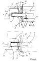
- Figure 1 shows a device for impact sound insulation vertical support of a component.
- the component is, for example, a Stair run 1 to be supported on a stair landing 2 is.
- the staircase 1 is a precast concrete part, that is prefabricated at the factory. In this manufacturing is a sleeve 3 acting as a receptacle in the Poured in concrete, the inside at their top one Has elastomer layer 4.
- the sleeve is made of steel, for example. she can but also from polymer concrete, fiber concrete, plastics or other materials.
- this sleeve 3 is after setting the concrete Stair run 1 used a transverse force mandrel 5, the the elastomer layer 4 rests, the remaining space between the sleeve 3 and the transverse force mandrel 5 by insulating material 6 is filled.
- this soft insulating material 6 on the one hand prevents the transverse force mandrel 5 and the sleeve 3 directly in contact with each other come, it is also achieved that the later Concreting the neighboring component in the concrete Gap between the transverse force mandrel 5 and sleeve 3 flows and possibly forms a rigid sound bridge.
- the transverse force mandrel 5 On his still free end, the transverse force mandrel 5 has an adjusting screw 7 on.
- the transverse force mandrel 5 can both a round as well as a rectangular cross section exhibit.
- the adjusting screw 7, which is shown in FIG. 1 is a hexagon screw, is set so that when lowering the staircase 1 with a Crane the undersides 11 and 12 of the element ceiling 8 or of stairs 1 merge into each other.
- the adjusting screw 7 is supported on a base plate 9 from.
- the dead weight of the stair run 1 tries the transverse force mandrel 5 around the contact point of the adjusting screw 7 to turn counterclockwise. This would but the front edge 13 of the elastomer layer 4 is squeezed and the elastomer layer could then be yours No longer fulfill the function of impact sound insulation. Around To prevent this, the sleeve 3 is locked in the form of a torque support for the transverse force mandrel 5 appropriate.
- This torque-supporting locking is shown in FIG formed by a pressure screw 14 and a counter bearing 15.
- the counter bearing 15 is made of an elastomer material and on the inside of the sleeve 3 below placed.
- the screw 14 runs through a tube 17 which extends from the top 16 of the flight of stairs up to as a recording acting sleeve 3 extends.
- the tube 17 prevents that the screw 14 in the manufacture of the flight of stairs 1 comes into direct contact with concrete and concreted in becomes.
- the screw 14 and the counter bearing 15 are in the axial direction of the transverse force mandrel spaced apart and act in opposite directions as pressure elements. This allows the shear force mandrel to be screwed over a moment can be applied as a support against the inclination mentioned above works. The shear force mandrel is locked in this way.
- the front 19 of the stair case is then suitable Joint material 20 is occupied and then the stair landing 2 is cast from concrete.
- This concrete encloses the free end of the transverse force mandrel 5 completely.
- the screw 14 can be removed become.
- the above-mentioned twisting of the shear force mandrel 5 is then through the set concrete of the stair landing 2 prevented.
- the tube 17 is then e.g. closed with a stopper and on the stairs run 1 becomes a stair covering 21 laid. Finally, the joints between Stair run and stair landing still elastic Joint material 22 closed.
- the mentioned joint material 20 between stairs and Stair landing can be used in addition to the acoustic function also take on the task of shear force in the event of a fire 5 protect from flames and heat. This is but also possible through other design features.
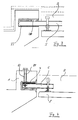
- the transverse force mandrel 5 thus lies on its entire upper surface on the elastomer layer 4 and the counter bearing 23 is relieved of pressure.
- the force of the lag screw 24 in the transverse force mandrel 5 takes place via an inside the transverse force mandrel arranged steel cube 25, in which the lag screw 24 through a hole in the transverse force mandrel 5 is screwed into it. But it is e.g. also possible, through a thread in or on the mandrel the force transmission ensure in the screw.
- the supporting forces of the Tension screw 24 are a wedge 26 in the Concrete of the staircase 1 initiated. Through the oblique Side of this wedge is a good distribution of forces reached. The resulting tensile force is determined by a Reinforcement 30 introduced into the concrete.
- An additional reinforcement 27 can be provided in the transverse force mandrel become.
- FIG. 3 is in place of a pressure screw as in Figure 1 provides a container in the form of a pressure can 28.
- This pressure cell forms together with the counter bearing 23 a torque-supporting lock.
- the pressure can is filled with a gel and has a wall through which the gel under pressure can diffuse outwards. After the stair run element placed on the stair landing this pressure is exerted on the pressure can 28. Diffusing out of the gel contained in the pressure can but goes very slowly, so that the locking of the shear force arbor lasts a long time and only very slowly subsides. Until this state is reached, that is Concrete of the stair landing 2 but already hardened and takes over the anti-rotation of the shear force mandrel 5. Even with such a locking of the mandrel automatically dismantling container is another complete acoustic decoupling of the shear force mandrel possible.
- the container 28 can also For example, be filled with sand, then through pulling a stopper to open a breech can and the sand then e.g. into the inside of the shear force mandrel 5 trickles. The container then loses its ability to transmit pressure and lock is canceled. It is also possible to do this in filling material located in the pressure cell by a dissolve physical and / or chemical process and the container thus its pressure transmission ability to take.
- FIG of the shear force mandrel Another possibility for locking is in FIG of the shear force mandrel.
- a Tension screw 29 becomes the transverse force mandrel 5 in the rear Area of the sleeve 3 up against the elastomer layer 4 biased. This will when you put the Stair run 1 on the element ceiling 8 of the stair landing 2 a the entire surface of the elastomer layer 4 occupying load between shear force 5 and Elastomer layer 4 reached. This load sharing due Prestress is also retained when the concrete of the stair landing 2 is solidified and the transverse force mandrel 5 clamps.
Landscapes
- Engineering & Computer Science (AREA)
- Architecture (AREA)
- Physics & Mathematics (AREA)
- Acoustics & Sound (AREA)
- Civil Engineering (AREA)
- Structural Engineering (AREA)
- Electromagnetism (AREA)
- Manufacturing Of Tubular Articles Or Embedded Moulded Articles (AREA)
- Vibration Dampers (AREA)
- Road Signs Or Road Markings (AREA)
- Sanitary Device For Flush Toilet (AREA)
- Forms Removed On Construction Sites Or Auxiliary Members Thereof (AREA)
Claims (12)
- Dispositif pour un élément d'appui vertical pour l'isolation acoustique des bruits de choc d'un premier élément de construction (1), notamment d'un élément préfabriqué en béton sur un second élément de construction (2) adjacent avec un logement (3) dans l'un des éléments de construction et avec un mandrin de force transversale (5) qui agit avec le logement (3) à l'une de ses extrémités et qui, sur son autre extrémité, dépasse en direction de l'autre élément de construction (2), une couche (4) élastique pour l'isolation acoustique des bruits de chocs étant placée dans la partie d'appui entre le logement (3) et le mandrin de force transversale (5), caractérisé en ce que le logement (3) est placé dans l'élément de construction à soutenir (1) et que le mandrin de force transversale (5) est maintenu dans le logement (3) à l'aide d'un dispositif d'arrêt (14, 15, 23, 24, 28, 29) essentiellement résistant à la torsion par rapport à son axe transversal horizontal et en ce que le dispositif d'arrêt peut être enlevé.
- Dispositif selon la revendication 1, caractérisé en ce que le dispositif d'arrêt présente deux moyens de transmission de force (14, 15; 23 , 24 ; 23, 28) placés à intervalle l'un de l'autre en direction axiale du mandrin de force transversale et agissant principalement à l'opposé sur un niveau vertical.
- Dispositif selon la revendication 2, caractérisé en ce qu'au moins un des moyens de transmission de force (14, 24, 29) est un raccord à vis accessible par la surface extérieure (16, 11) de l'élément de construction (1).
- Dispositif selon la revendication 3, caractérisé en ce que le raccord à vis (14) reçoit des forces de pression.
- Dispositif selon la revendication 3, caractérisé en ce que le raccord à vis (24, 29) reçoit des forces de traction.
- Dispositif selon la revendication 3, caractérisé en ce que l'accessibilité du raccord à vis (14, 24, 29) est assurée par un tube (17) s'étendant parallèlement à l'axe de la vis et traversant le matériau de l'élément de construction (1) entourant le logement (3).
- Dispositif selon la revendication 2, caractérisé en ce qu'au moins un moyen de transmission de force est un récipient (28) rempli dont la fonction de transmission de force peut être annulée par des réactions physiques et/ou chimiques.
- Dispositif selon la revendication 7, caractérisé en ce que le récipient contient un matériau de remplissage qui, sous pression, pénètre au travers des parois du récipient.
- Dispositif selon la revendication 7, caractérisé en ce que le récipient peut être vidé par une ouverture ouvrable de l'extérieur.
- Dispositif selon la revendication 7, caractérisé en ce qu'un moyen peut être amené dans le récipient, ou y est déjà contenu, qui dissout le récipient, le matériau de remplissage ou des parties de celui-ci et annule ainsi la fonction du récipient.
- Dispositif selon la revendication 2, caractérisé en ce qu'un moyen de transmission de force est une butée (23) notamment en élastomère.
- Dispositif selon la revendication 1, caractérisé en ce que le mandrin de force transversale présente sur son extrémité libre un ajustage en hauteur notamment une vis (7) pour l'élément de construction (1).
Applications Claiming Priority (2)
| Application Number | Priority Date | Filing Date | Title |
|---|---|---|---|
| DE4429605A DE4429605A1 (de) | 1994-08-20 | 1994-08-20 | Trittschalldämmendes Auflagerelement |
| DE4429605 | 1994-08-20 |
Publications (2)
| Publication Number | Publication Date |
|---|---|
| EP0697489A1 EP0697489A1 (fr) | 1996-02-21 |
| EP0697489B1 true EP0697489B1 (fr) | 1999-04-07 |
Family
ID=6526193
Family Applications (1)
| Application Number | Title | Priority Date | Filing Date |
|---|---|---|---|
| EP95107649A Expired - Lifetime EP0697489B1 (fr) | 1994-08-20 | 1995-05-19 | Elément d'appui pour l'isolation acoustique des bruits de chocs |
Country Status (3)
| Country | Link |
|---|---|
| EP (1) | EP0697489B1 (fr) |
| AT (1) | ATE178682T1 (fr) |
| DE (2) | DE4429605A1 (fr) |
Families Citing this family (7)
| Publication number | Priority date | Publication date | Assignee | Title |
|---|---|---|---|---|
| CH688383A5 (de) * | 1994-12-12 | 1997-08-29 | Egco Ag | Querkraftdornlager. |
| DE29504707U1 (de) * | 1995-03-24 | 1995-05-04 | Schöck Bauteile GmbH, 76534 Baden-Baden | Fugenplatte |
| DE19602306B4 (de) * | 1996-01-23 | 2004-02-19 | Schöck Entwicklungsgesellschaft mbH | Tragvorrichtung |
| EP0816587B1 (fr) * | 1996-06-27 | 2005-10-26 | HM-Betonfertigteilwerk Hans Mauthe GmbH & Co. KG | Support pour escalier préfabriqué |
| DE202005008862U1 (de) * | 2005-06-07 | 2005-08-11 | Schöck Bauteile GmbH | Treppenbauteil |
| DE102011009762A1 (de) * | 2011-01-28 | 2012-08-02 | Schöck Bauteile GmbH | Bauelement zum Einbau in Trennfugen von Gebäuden |
| DE102012002168A1 (de) * | 2012-02-07 | 2013-08-08 | Schöck Bauteile GmbH | Bauelement zum Einbau in Trennfugen von Gebäuden |
Citations (2)
| Publication number | Priority date | Publication date | Assignee | Title |
|---|---|---|---|---|
| CH376623A (de) * | 1959-11-23 | 1964-04-15 | Schmid Peter | Gestell aus Profilstücken, die mindestens zum Teil lösbar und verstellbar miteinander verbunden sind |
| CH415999A (de) * | 1964-05-11 | 1966-06-30 | Straessle Marcel | Gestell mit mindestens einer profilierten Stange |
Family Cites Families (8)
| Publication number | Priority date | Publication date | Assignee | Title |
|---|---|---|---|---|
| DD98967A1 (fr) * | 1972-07-06 | 1973-07-12 | ||
| CH562968A5 (en) * | 1973-03-01 | 1975-06-13 | Syma Intercontinental Sa | Coupling device for walls and frame components - has anchor with conical end enclosed in expanding ring |
| DD128548B1 (de) * | 1976-11-09 | 1980-01-30 | Rudolf Dietz | Vorrichtung zur montage und auflagerung flaechenfoermiger bauelemente |
| DE7827042U1 (de) | 1978-09-12 | 1978-12-21 | Georg Jaeger & Sohn Kg, 6310 Gruenberg | Innentreppe, insbesondere fuer reihenhaeuser |
| DE3408556A1 (de) * | 1984-03-08 | 1985-09-12 | Eberhard Ing.(grad.) 7570 Baden-Baden Schöck | Trennelement fuer betonplatten |
| DE8702129U1 (de) * | 1987-02-12 | 1987-04-16 | Udo Fuchs GmbH, 7968 Saulgau | Elastische Muffe zur Schalldämmung bei Fertigtreppen |
| DE4002661A1 (de) * | 1990-01-30 | 1991-08-01 | Schoeck Bauteile Gmbh | Konsolelement zur uebertragung allein vertikaler kraefte in gebaeuden |
| ES2084327T3 (es) * | 1991-11-29 | 1996-05-01 | Toni H Erb | Disposicion de union de una espina de empuje. |
-
1994
- 1994-08-20 DE DE4429605A patent/DE4429605A1/de not_active Withdrawn
-
1995
- 1995-05-19 EP EP95107649A patent/EP0697489B1/fr not_active Expired - Lifetime
- 1995-05-19 DE DE59505565T patent/DE59505565D1/de not_active Expired - Fee Related
- 1995-05-19 AT AT95107649T patent/ATE178682T1/de not_active IP Right Cessation
Patent Citations (2)
| Publication number | Priority date | Publication date | Assignee | Title |
|---|---|---|---|---|
| CH376623A (de) * | 1959-11-23 | 1964-04-15 | Schmid Peter | Gestell aus Profilstücken, die mindestens zum Teil lösbar und verstellbar miteinander verbunden sind |
| CH415999A (de) * | 1964-05-11 | 1966-06-30 | Straessle Marcel | Gestell mit mindestens einer profilierten Stange |
Also Published As
| Publication number | Publication date |
|---|---|
| DE4429605A1 (de) | 1996-02-22 |
| ATE178682T1 (de) | 1999-04-15 |
| EP0697489A1 (fr) | 1996-02-21 |
| DE59505565D1 (de) | 1999-05-12 |
Similar Documents
| Publication | Publication Date | Title |
|---|---|---|
| EP3112542B1 (fr) | Dispositif et procede de couplage thermique de parties betonnees de batiment | |
| EP0433224A1 (fr) | Elément de support composite | |
| EP2715013B1 (fr) | Ensemble d'assemblage et procédé de production d'une consolidation contre la perforation, d'un renfort de force transversale supplémentaire ou d'un raccordement d'armature | |
| EP0697489B1 (fr) | Elément d'appui pour l'isolation acoustique des bruits de chocs | |
| EP1405961A1 (fr) | Structure en acier-béton pour dalles de plancher | |
| EP2610410A2 (fr) | Elément de construction pour l'isolation thermique | |
| EP1482101A1 (fr) | Elément de construction, procédé pour fabriquer des éléments de construction et moyens de liaison pour élément de construction | |
| DE19501277C2 (de) | Beton-Fertigteil-Balkon | |
| DE19928757C2 (de) | Montageträgersystem und Verfahren zur Montage eines Fertigbauteils an einem Gebäudeteil | |
| DE19630552C2 (de) | Bauelement zur Wärmedämmung | |
| EP3161226B1 (fr) | Cheville d'ancrage | |
| EP1860246B1 (fr) | Elément de construction pour isolation thermique | |
| DE19639576A1 (de) | Befestigung der Säule eines Schwenkkranes | |
| DE29917220U1 (de) | Montageträgersystem mit Einbauhilfe | |
| EP2069581B1 (fr) | Construction en béton armé pour un bâtiment, et procédé permettant d'ériger ladite structure | |
| DE1683121A1 (de) | Spindeltreppe | |
| DE3302075A1 (de) | Spannbeton- oder stahlbetonbiegetraeger | |
| DE20219324U1 (de) | Gebäudegeschoss | |
| DE19724393A1 (de) | Wandstützenbefestigung | |
| DE102025132360A1 (de) | Wangenfreie Treppe, insbesondere Kragarmtreppe, Befestigung einer Stufe an einer aufstrebenden Wand einer wangenfreien Treppe und Verfahren zur Herstellung einer wangenfreien Treppe, insbesondere Kragarmtreppe | |
| AT523024B1 (de) | Gebäudekonstruktion und Verfahren zur Bildung derselben | |
| DE19806164A1 (de) | Trittschalldämmendes Auflagerelement | |
| DE7733030U1 (de) | Vorgefertigte montagetreppe | |
| EP3611310A1 (fr) | Ancre de garde-corps | |
| EP0826845A2 (fr) | Dispositif de reprise des efforts de traction |
Legal Events
| Date | Code | Title | Description |
|---|---|---|---|
| PUAI | Public reference made under article 153(3) epc to a published international application that has entered the european phase |
Free format text: ORIGINAL CODE: 0009012 |
|
| AK | Designated contracting states |
Kind code of ref document: A1 Designated state(s): AT BE CH DE DK FR GB IT LI LU NL SE |
|
| 17P | Request for examination filed |
Effective date: 19960122 |
|
| 17Q | First examination report despatched |
Effective date: 19980217 |
|
| GRAG | Despatch of communication of intention to grant |
Free format text: ORIGINAL CODE: EPIDOS AGRA |
|
| GRAG | Despatch of communication of intention to grant |
Free format text: ORIGINAL CODE: EPIDOS AGRA |
|
| GRAH | Despatch of communication of intention to grant a patent |
Free format text: ORIGINAL CODE: EPIDOS IGRA |
|
| GRAH | Despatch of communication of intention to grant a patent |
Free format text: ORIGINAL CODE: EPIDOS IGRA |
|
| GRAA | (expected) grant |
Free format text: ORIGINAL CODE: 0009210 |
|
| AK | Designated contracting states |
Kind code of ref document: B1 Designated state(s): AT BE CH DE DK FR GB IT LI LU NL SE |
|
| PG25 | Lapsed in a contracting state [announced via postgrant information from national office to epo] |
Ref country code: SE Free format text: THE PATENT HAS BEEN ANNULLED BY A DECISION OF A NATIONAL AUTHORITY Effective date: 19990407 Ref country code: NL Free format text: LAPSE BECAUSE OF FAILURE TO SUBMIT A TRANSLATION OF THE DESCRIPTION OR TO PAY THE FEE WITHIN THE PRESCRIBED TIME-LIMIT Effective date: 19990407 Ref country code: IT Free format text: LAPSE BECAUSE OF FAILURE TO SUBMIT A TRANSLATION OF THE DESCRIPTION OR TO PAY THE FEE WITHIN THE PRE;WARNING: LAPSES OF ITALIAN PATENTS WITH EFFECTIVE DATE BEFORE 2007 MAY HAVE OCCURRED AT ANY TIME BEFORE 2007. THE CORRECT EFFECTIVE DATE MAY BE DIFFERENT FROM THE ONE RECORDED.SCRIBED TIME-LIMIT Effective date: 19990407 Ref country code: GB Free format text: LAPSE BECAUSE OF NON-PAYMENT OF DUE FEES Effective date: 19990407 Ref country code: FR Free format text: LAPSE BECAUSE OF FAILURE TO SUBMIT A TRANSLATION OF THE DESCRIPTION OR TO PAY THE FEE WITHIN THE PRESCRIBED TIME-LIMIT Effective date: 19990407 |
|
| REF | Corresponds to: |
Ref document number: 178682 Country of ref document: AT Date of ref document: 19990415 Kind code of ref document: T |
|
| REG | Reference to a national code |
Ref country code: CH Ref legal event code: EP |
|
| REF | Corresponds to: |
Ref document number: 59505565 Country of ref document: DE Date of ref document: 19990512 |
|
| PG25 | Lapsed in a contracting state [announced via postgrant information from national office to epo] |
Ref country code: LU Free format text: LAPSE BECAUSE OF NON-PAYMENT OF DUE FEES Effective date: 19990519 Ref country code: AT Free format text: LAPSE BECAUSE OF NON-PAYMENT OF DUE FEES Effective date: 19990519 |
|
| PG25 | Lapsed in a contracting state [announced via postgrant information from national office to epo] |
Ref country code: LI Free format text: LAPSE BECAUSE OF NON-PAYMENT OF DUE FEES Effective date: 19990531 Ref country code: CH Free format text: LAPSE BECAUSE OF NON-PAYMENT OF DUE FEES Effective date: 19990531 Ref country code: BE Free format text: LAPSE BECAUSE OF NON-PAYMENT OF DUE FEES Effective date: 19990531 |
|
| PG25 | Lapsed in a contracting state [announced via postgrant information from national office to epo] |
Ref country code: DK Free format text: LAPSE BECAUSE OF FAILURE TO SUBMIT A TRANSLATION OF THE DESCRIPTION OR TO PAY THE FEE WITHIN THE PRESCRIBED TIME-LIMIT Effective date: 19990707 |
|
| NLV1 | Nl: lapsed or annulled due to failure to fulfill the requirements of art. 29p and 29m of the patents act | ||
| EN | Fr: translation not filed | ||
| GBV | Gb: ep patent (uk) treated as always having been void in accordance with gb section 77(7)/1977 [no translation filed] |
Effective date: 19990407 |
|
| BERE | Be: lapsed |
Owner name: SCHOCK BAUTEILE G.M.B.H. Effective date: 19990531 |
|
| REG | Reference to a national code |
Ref country code: CH Ref legal event code: PL |
|
| PLBE | No opposition filed within time limit |
Free format text: ORIGINAL CODE: 0009261 |
|
| STAA | Information on the status of an ep patent application or granted ep patent |
Free format text: STATUS: NO OPPOSITION FILED WITHIN TIME LIMIT |
|
| 26N | No opposition filed | ||
| PGFP | Annual fee paid to national office [announced via postgrant information from national office to epo] |
Ref country code: DE Payment date: 20010529 Year of fee payment: 7 |
|
| GBT | Gb: translation of ep patent filed (gb section 77(6)(a)/1977) |
Effective date: 20010712 |
|
| PG25 | Lapsed in a contracting state [announced via postgrant information from national office to epo] |
Ref country code: DE Free format text: LAPSE BECAUSE OF NON-PAYMENT OF DUE FEES Effective date: 20021203 |