EP0697509A2 - Commande de vitesse élevée de ralenti et méthode d'opération - Google Patents
Commande de vitesse élevée de ralenti et méthode d'opération Download PDFInfo
- Publication number
- EP0697509A2 EP0697509A2 EP95111442A EP95111442A EP0697509A2 EP 0697509 A2 EP0697509 A2 EP 0697509A2 EP 95111442 A EP95111442 A EP 95111442A EP 95111442 A EP95111442 A EP 95111442A EP 0697509 A2 EP0697509 A2 EP 0697509A2
- Authority
- EP
- European Patent Office
- Prior art keywords
- speed
- sensor
- signal
- idle
- engine
- Prior art date
- Legal status (The legal status is an assumption and is not a legal conclusion. Google has not performed a legal analysis and makes no representation as to the accuracy of the status listed.)
- Granted
Links
- 238000000034 method Methods 0.000 title claims 5
- 238000002485 combustion reaction Methods 0.000 claims abstract description 3
- 230000005540 biological transmission Effects 0.000 claims description 15
- 230000007935 neutral effect Effects 0.000 claims description 13
- 230000000994 depressogenic effect Effects 0.000 claims description 5
- 239000000446 fuel Substances 0.000 description 13
- 238000010586 diagram Methods 0.000 description 1
- 230000000007 visual effect Effects 0.000 description 1
Images


Classifications
-
- F—MECHANICAL ENGINEERING; LIGHTING; HEATING; WEAPONS; BLASTING
- F02—COMBUSTION ENGINES; HOT-GAS OR COMBUSTION-PRODUCT ENGINE PLANTS
- F02D—CONTROLLING COMBUSTION ENGINES
- F02D41/00—Electrical control of supply of combustible mixture or its constituents
- F02D41/02—Circuit arrangements for generating control signals
- F02D41/04—Introducing corrections for particular operating conditions
- F02D41/08—Introducing corrections for particular operating conditions for idling
- F02D41/083—Introducing corrections for particular operating conditions for idling taking into account engine load variation, e.g. air-conditionning
-
- B—PERFORMING OPERATIONS; TRANSPORTING
- B60—VEHICLES IN GENERAL
- B60W—CONJOINT CONTROL OF VEHICLE SUB-UNITS OF DIFFERENT TYPE OR DIFFERENT FUNCTION; CONTROL SYSTEMS SPECIALLY ADAPTED FOR HYBRID VEHICLES; ROAD VEHICLE DRIVE CONTROL SYSTEMS FOR PURPOSES NOT RELATED TO THE CONTROL OF A PARTICULAR SUB-UNIT
- B60W10/00—Conjoint control of vehicle sub-units of different type or different function
- B60W10/02—Conjoint control of vehicle sub-units of different type or different function including control of driveline clutches
-
- B—PERFORMING OPERATIONS; TRANSPORTING
- B60—VEHICLES IN GENERAL
- B60W—CONJOINT CONTROL OF VEHICLE SUB-UNITS OF DIFFERENT TYPE OR DIFFERENT FUNCTION; CONTROL SYSTEMS SPECIALLY ADAPTED FOR HYBRID VEHICLES; ROAD VEHICLE DRIVE CONTROL SYSTEMS FOR PURPOSES NOT RELATED TO THE CONTROL OF A PARTICULAR SUB-UNIT
- B60W10/00—Conjoint control of vehicle sub-units of different type or different function
- B60W10/04—Conjoint control of vehicle sub-units of different type or different function including control of propulsion units
-
- B—PERFORMING OPERATIONS; TRANSPORTING
- B60—VEHICLES IN GENERAL
- B60W—CONJOINT CONTROL OF VEHICLE SUB-UNITS OF DIFFERENT TYPE OR DIFFERENT FUNCTION; CONTROL SYSTEMS SPECIALLY ADAPTED FOR HYBRID VEHICLES; ROAD VEHICLE DRIVE CONTROL SYSTEMS FOR PURPOSES NOT RELATED TO THE CONTROL OF A PARTICULAR SUB-UNIT
- B60W10/00—Conjoint control of vehicle sub-units of different type or different function
- B60W10/04—Conjoint control of vehicle sub-units of different type or different function including control of propulsion units
- B60W10/06—Conjoint control of vehicle sub-units of different type or different function including control of propulsion units including control of combustion engines
-
- B—PERFORMING OPERATIONS; TRANSPORTING
- B60—VEHICLES IN GENERAL
- B60W—CONJOINT CONTROL OF VEHICLE SUB-UNITS OF DIFFERENT TYPE OR DIFFERENT FUNCTION; CONTROL SYSTEMS SPECIALLY ADAPTED FOR HYBRID VEHICLES; ROAD VEHICLE DRIVE CONTROL SYSTEMS FOR PURPOSES NOT RELATED TO THE CONTROL OF A PARTICULAR SUB-UNIT
- B60W10/00—Conjoint control of vehicle sub-units of different type or different function
- B60W10/10—Conjoint control of vehicle sub-units of different type or different function including control of change-speed gearings
- B60W10/11—Stepped gearings
-
- B—PERFORMING OPERATIONS; TRANSPORTING
- B60—VEHICLES IN GENERAL
- B60W—CONJOINT CONTROL OF VEHICLE SUB-UNITS OF DIFFERENT TYPE OR DIFFERENT FUNCTION; CONTROL SYSTEMS SPECIALLY ADAPTED FOR HYBRID VEHICLES; ROAD VEHICLE DRIVE CONTROL SYSTEMS FOR PURPOSES NOT RELATED TO THE CONTROL OF A PARTICULAR SUB-UNIT
- B60W10/00—Conjoint control of vehicle sub-units of different type or different function
- B60W10/18—Conjoint control of vehicle sub-units of different type or different function including control of braking systems
-
- B—PERFORMING OPERATIONS; TRANSPORTING
- B60—VEHICLES IN GENERAL
- B60W—CONJOINT CONTROL OF VEHICLE SUB-UNITS OF DIFFERENT TYPE OR DIFFERENT FUNCTION; CONTROL SYSTEMS SPECIALLY ADAPTED FOR HYBRID VEHICLES; ROAD VEHICLE DRIVE CONTROL SYSTEMS FOR PURPOSES NOT RELATED TO THE CONTROL OF A PARTICULAR SUB-UNIT
- B60W30/00—Purposes of road vehicle drive control systems not related to the control of a particular sub-unit, e.g. of systems using conjoint control of vehicle sub-units
- B60W30/18—Propelling the vehicle
- B60W30/1819—Propulsion control with control means using analogue circuits, relays or mechanical links
-
- B—PERFORMING OPERATIONS; TRANSPORTING
- B60—VEHICLES IN GENERAL
- B60W—CONJOINT CONTROL OF VEHICLE SUB-UNITS OF DIFFERENT TYPE OR DIFFERENT FUNCTION; CONTROL SYSTEMS SPECIALLY ADAPTED FOR HYBRID VEHICLES; ROAD VEHICLE DRIVE CONTROL SYSTEMS FOR PURPOSES NOT RELATED TO THE CONTROL OF A PARTICULAR SUB-UNIT
- B60W30/00—Purposes of road vehicle drive control systems not related to the control of a particular sub-unit, e.g. of systems using conjoint control of vehicle sub-units
- B60W30/18—Propelling the vehicle
- B60W30/188—Controlling power parameters of the driveline, e.g. determining the required power
- B60W30/1886—Controlling power supply to auxiliary devices
- B60W30/1888—Control of power take off [PTO]
Definitions
- the present invention generally relates to electronic engine controls, and more specifically, relates to an elevated idle speed control that permits the engine operator to select an elevated engine idling speed.
- PTO power-take-off
- the PTO generally includes a rotating shaft extending rearwardly from the cab.
- the device to be powered is then connected to the PTO shaft.
- power is transmitted to the device.
- One such device is a refrigerated trailer. In some refrigerated trailers the PTO is used to power the compressor to keep the trailer at the desired refrigerated temperature.
- Other vehicles that have a PTO include utility vehicles, school buses and firetrucks.
- the truck engine provides power to both the PTO and the drive train of the truck.
- the engine speed is generally high enough to provide sufficient power for both the PTO and the transmission.
- the engine may not produce sufficient power to drive the external device connected to the PTO.
- the operator is required to press the accelerator pedal to elevate the idle speed to cause the engine to produce more power.
- manually maintaining a desired elevated idle speed is inefficient and prevents the operator from sleeping or performing other tasks when the truck is stopped and idling.
- an apparatus for selectively commanding an elevated high idle mode preferably includes a toggle switch or other means for causing the engine to enter a high idle mode.
- High idle mode will normally be selectable when the brake pedal is not pressed, the clutch pedal is not pressed, the vehicle is travelling below a certain predetermined speed, and the gear selector is in neutral.
- the idle speed will correspond to the default valve. If the engine speed exceeds a maximum high idle value when the toggle switch is activated, then the idle speed will correspond to the maximum high idle value. If the engine speed is greater than the default value but less than the maximum high idle value when the toggle switch is activated, then the idle speed will correspond to the engine speed.
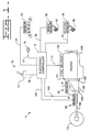
- the elevated idle speed control 10 is used in connection with an internal combustion engine 100 having fuel delivery means 110 associated therewith.
- a flywheel 120 rotatably connected to a transmission 130 to transmit power from the engine 100 to a drivewheel 170 of the vehicle.
- the transmission is also connected to a second flywheel 140.
- the second flywheel 140 transmits power to a rotatable driveshaft 150 which, in connection with other gearing (not shown) causes the drive wheels 170 of the vehicle to turn, thereby propelling the vehicle.
- the elevated idle speed control 10 includes an electronic controller 15, which is electrically connected to a gear selector sensor 20 via electrical connector 25, to a brake pedal sensor 30 via electrical connector 35, and to a clutch pedal sensor 40 via electrical connector 45.
- a high idle mode indicator lamp 16 is also connected to the electronic controller 15 via an electrical connector 17.
- the gear selector sensor 20 is associated with a gear shift or gear selector lever (not shown) and produces a neutral signal when the gear selector lever is in a neutral position and the transmission is therefore in neutral.
- the electronic controller 15 inputs the neutral signal from electrical connector 25.
- a gear selector sensor might not be utilized. Such an embodiment might arise where the vehicle has a manual transmission.
- the brake pedal sensor 30 is associated with the brake pedal 32 and produces a brake pedal engaged signal when the truck operator has depressed the brake pedal 32.
- the electronic controller 15 inputs the brake pedal engaged signal from electrical connector 35.
- the clutch pedal sensor 40 is associated with the clutch pedal 42 and produces a clutch pedal engaged signal when the truck operator has depressed the clutch pedal 42.
- the electronic controller 15 inputs the clutch pedal engaged signal from electrical connector 45.
- other embodiments particularly those applications involving automatic transmissions where a clutch pedal is not used, may not have a clutch pedal sensor 40. Those embodiments will nevertheless fall within the scope of the present invention as defined by the appended claims.
- the engine speed determining means 50 includes a flywheel 120 associated with the engine 100.
- the flywheel 120 preferably includes teeth 121 or other features that are capable of being sensed as the flywheel 120 rotates.
- An engine speed sensor 51 is preferably installed in proximity to the flywheel 120 to permit the sensor 51 to sense the flywheel teeth 121 as the flywheel 120 rotates.
- the engine speed sensor 51 produces a signal that is a function of the rotational velocity of the flywheel 120, which in turn is a function of the engine speed.
- the electronic controller 15 inputs the engine speed signal from an electrical connector 125.
- the means for determining the vehicle speed 60 preferably includes a second flywheel 140 that rotates at a speed that is a function of the speed of the rotating driveshaft 150.
- the second flywheel 140 preferably includes teeth 141 or other features such as slots that are capable of being sensed when the second flywheel 140 rotates.
- a vehicle speed sensor 61 is located proximate to the second flywheel 140 such that the vehicle speed sensor can sense the passing of the teeth 141 or other features as the flywheel 140 rotates.
- the vehicle speed sensor 140 produces a vehicle speed signal that is a function of the rotational velocity of the second flywheel 140, which in turn is a function of the speed of the drive shaft and the vehicle.
- the electronic controller 15 inputs the vehicle speed signal over an electrical connector 145.
- the high idle mode selection means 70 preferably includes a two position toggle switch 75 that is biased to a first position. An operator can toggle the switch 75 to a second position, but when the operator releases the toggle switch 75 it returns to the first position.
- the toggle switch 75 produces a toggle switch signal when said switch is in the second position.
- the electronic controller 15 inputs the toggle switch signal over an electrical connector 76.
- the electronic controller 15 produces a fuel command that is delivered to the fuel delivery means 110.
- the fuel command determines the quantity of fuel that will be delivered to the individual engine cylinders and therefore, in part, determines the rotational velocity of the engine.
- the fuel delivery means includes a plurality of electronically controlled fuel injectors (not shown).
- the present invention is not limited to engines having fuel injectors and includes other fuel delivery systems.
- the electronic controller 15 issues a fuel delivery command over an electrical connector 111.
- FIG. 2 a flowchart of the software control implemented in a preferred embodiment of the present invention is disclosed.
- the software necessary to perform the functions detailed in the flowchart can be readily and easily written by one skilled in the art using the instruction set for the specific microprocessor or electronic controller used in connection with the present invention.
- a preferred embodiment of the present invention uses a Motorola 68HC11, although other suitable microprocessors can be readily and easily substituted without deviating from the spirit and scope of the present invention as defined by the appended claims.
- Block 200 starts the software control implemented in a preferred embodiment of the invention.
- Software control passes to block 210.
- the electronic controller 15 sets the variable IDLE MODE equal to NORMAL IDLE MODE.
- the electronic controller 15 uses the IDLE MODE variable to assign the current operating mode. If the controller is currently operating in HIGH IDLE MODE, then the IDLE MODE variable is set to HIGH IDLE MODE. On the other hand, if the electronic controller 15 is operating in NORMAL IDLE MODE, then the IDLE MODE VARIABLE is set to NORMAL IDLE MODE.
- the electronic controller initializes the IDLE MODE variable to NORMAL IDLE MODE.
- Software control then passes to block 220.
- the electronic controller 15 determines whether the gear selector sensor 20 is producing a neutral signal on the electrical connector 25, which indicates that the gear selector, and thus the transmission 130, is in neutral. If the gear selector sensor is producing a neutral signal then software control passes to block 230. Otherwise, control passes to block 205.
- the electronic controller 15 determines whether the brake sensor 30 is producing a brake engaged signal on the electrical connector 35. If so, then software control passes to block 240. Otherwise, software control passes to block 205.
- the electronic controller 15 determines whether the clutch sensor 40 is producing a clutch engaged signal on electrical connector 45. If the clutch sensor 40 is producing a clutch engaged signal, then software control passes to block 205. Otherwise, software control passes to block 250.
- the electronic controller 15 inputs the vehicle speed signal produced by the vehicle speed sensor 61 on electrical connector 145. If the vehicle speed signal corresponds to a vehicle speed less than a first predetermined vehicle speed (SPD1) then software control passes to block 260. Otherwise software control passes to block 205.
- the first predetermined vehicle speed SPD1 value is selected so that the electronic controller can determine that the vehicle is stopped, or only moving very slowly despite that the transmission 130 is in neutral. In a preferred embodiment, SPD1 is selected as approximately seven miles-per-hour. However, it should be recognized that other similar values could be readily and easily substituted for this value without deviating from the spirit and scope of the present invention as defined by the appended claims.
- the combination of software blocks 220-250 represent a set of conditions that generally must exist before the operator can cause the engine controller 15 to enter HIGH IDLE MODE. Those conditions include: the transmission being in neutral, the brakes not being engaged, the clutch not being engaged, and the vehicle speed being below seven miles-per-hour. As described below, when the operator then selects HIGH IDLE MODE through use of the high idle mode selection means 70, the engine controller 15 will issue a fuel delivery command corresponding to one of a maximum high idle speed, a desired high idle speed or a default high idle speed.
- the software control passes to block 260.
- the electronic controller 15 monitors the electrical connector 76 to determine whether a signal from the toggle switch 75 is present for more than a predetermined period of time (x time). The toggle switch 75 produces the signal when the operator moves the toggle switch 75 to the second position. If the electronic controller 15 determines that the toggle switch 75 has been in the second position for more than the predetermined period of time (x time), then control passes to block 270. Otherwise, control returns to block 220.
- the electronic controller reads the variable IDLE MODE and determines whether the IDLE MODE variable is set to HIGH IDLE MODE. If the current IDLE MODE VARIABLE equals HIGH IDLE MODE then software control passes to block 205. In this manner, when the engine is operating in HIGH IDLE MODE, the operator can return to NORMAL IDLE MODE by moving the toggle switch 75 to the second position for more than the predetermined period of time.
- the electronic controller 15 causes the fast idle lamp 16 on the operator display panel to be extinguished. This provides a visual indication to the operator that the electronic controller has returned to a NORMAL IDLE MODE.
- Software control then passes to block 210 where the electronic controller 15 sets the IDLE MODE variable to NORMAL IDLE MODE and software control passes to block 220.
- IDLE MODE does not equal HIGH IDLE MODE
- software control passes to block 280.
- the IDLE MODE VARIABLE will be NORMAL IDLE MODE in block 270 when the engine was operating in NORMAL IDLE MODE and the operator moved the toggle switch 75 to the second position for more than the predetermined period of time. This indicates to the electronic controller 15 that the operator desires to be in HIGH IDLE MODE.
- the electronic controller 15 sets the IDLE MODE to HIGH IDLE MODE. Control then passes to block 290.
- the electronic controller 15 causes the fast idle lamp 16 on the operator dash board to light, thereby indicating that the electronic controller 15 is operating in HIGH IDLE MODE.
- Software control then passes to block 300.
- the electronic controller 15 stores a value in an IDLE SPEED COMMAND variable.
- the electronic controller 15 uses the value stored in the IDLE SPEED COMMAND variable to calculate the fuel delivery command issued to the fuel delivery mean 110 when the engine is idling and the IDLE MODE variable is in HIGH IDLE MODE.
- the electronic controller 15 monitors the engine speed signal produced on electrical connector 125 by the engine speed determining means 50. If the engine speed signal on electrical connector 125 corresponds to an engine speed greater than a maximum high idle value (MAX HIGH IDLE), then software control passes to block 305.
- the maximum high idle value MAX HIGH IDLE
- the maximum high idle value is about 1600 RPM.
- a preferred embodiment of the present invention causes the electronic controller 15 to set the IDLE SPEED COMMAND equal to an idle speed corresponding to the maximum high idle value.
- the combination of blocks 300 and 305 causes the maximum high idle speed to be set to 1600 RPM.
- the electronic controller 15 determines whether the engine speed signal on connector 125 corresponds to an engine speed signal greater than a predetermined DEFAULT HIGH IDLE SPEED (DFLT SPD).
- DFLT SPD DEFAULT HIGH IDLE SPEED
- the DEFAULT HIGH IDLE SPEED is approximately 1200 RPM.
- the engine speed signal is greater than the DEFAULT HIGH IDLE SPEED (DFLT SPD)
- software control passes to block 315. Otherwise control passes to block 320.
- the electronic controller 15 sets the IDLE SPEED COMMAND equal to the engine speed corresponding to the engine speed signal on electrical connector 125.
- the IDLE SPEED COMMAND will be set to the engine speed.
- the operator can press an engine accelerator pedal to increase the engine speed and when the engine speed reaches a desired HIGH IDLE SPEED the operator toggles the toggle switch 75 to the second position for greater than the predetermined length of time (x time).
- the electronic controller 15 then programs the IDLE SPEED COMMAND to equal the engine speed corresponding to the engine speed signal on electrical connector 125.
- IDLE SPEED COMMAND the engine speed corresponding to the engine speed signal on electrical connector 125.
- a preferred embodiment of the present invention permits the operator to select a desired high idle speed within the limits established by the DEFAULT HIGH IDLE SPEED and the MAXIMUM HIGH IDLE SPEED.
- the IDLE SPEED COMMAND is set to a DEFAULT HIGH IDLE SPEED (DFLT SPD).
- DFLT SPD DEFAULT HIGH IDLE SPEED
- the DFLT SPD is approximately 1200 RPM.
- the operator can selectively choose the high idle mode when the conditions of blocks 210-250 are satisfied and the operator toggles the toggle switch 75 to the second position for more than the predetermined period of time (x time).
- the operator can select a desired idle speed, less than a maximum high idle speed, by pressing an accelerator pedal while the switch 75 is toggled. Otherwise, the high idle speed will correspond to a default speed.
- an embodiment of the present invention permits the operator to cause the engine to idle at a higher than normal speed. This allows the engine to maintain power output levels necessary to drive devices connected to the engine PTO when the engine is idling.
Landscapes
- Engineering & Computer Science (AREA)
- Chemical & Material Sciences (AREA)
- Combustion & Propulsion (AREA)
- Mechanical Engineering (AREA)
- Transportation (AREA)
- Automation & Control Theory (AREA)
- General Engineering & Computer Science (AREA)
- Control Of Vehicle Engines Or Engines For Specific Uses (AREA)
- Electrical Control Of Air Or Fuel Supplied To Internal-Combustion Engine (AREA)
Applications Claiming Priority (2)
| Application Number | Priority Date | Filing Date | Title |
|---|---|---|---|
| US290263 | 1994-08-15 | ||
| US08/290,263 US5480364A (en) | 1994-08-15 | 1994-08-15 | Elevated idle speed control and method of operating same |
Publications (3)
| Publication Number | Publication Date |
|---|---|
| EP0697509A2 true EP0697509A2 (fr) | 1996-02-21 |
| EP0697509A3 EP0697509A3 (fr) | 1998-10-28 |
| EP0697509B1 EP0697509B1 (fr) | 2001-05-23 |
Family
ID=23115214
Family Applications (1)
| Application Number | Title | Priority Date | Filing Date |
|---|---|---|---|
| EP95111442A Expired - Lifetime EP0697509B1 (fr) | 1994-08-15 | 1995-07-20 | Commande de vitesse élevée de ralenti et méthode d'opération |
Country Status (3)
| Country | Link |
|---|---|
| US (1) | US5480364A (fr) |
| EP (1) | EP0697509B1 (fr) |
| DE (1) | DE69520987T2 (fr) |
Cited By (5)
| Publication number | Priority date | Publication date | Assignee | Title |
|---|---|---|---|---|
| FR2840266A1 (fr) * | 2002-05-29 | 2003-12-05 | Visteon Global Tech Inc | Procede et dispositif pour commander une regulation de roulement au ralenti de vehicule |
| FR2866389A1 (fr) * | 2004-02-14 | 2005-08-19 | Bosch Gmbh Robert | Procede et dispositif de gestion d'un vehicule automobile |
| GB2490319A (en) * | 2011-04-20 | 2012-10-31 | Ford Global Tech Llc | Method and apparatus of operating a vehicle during take-off from rest |
| CN103261643A (zh) * | 2010-12-21 | 2013-08-21 | 斗山英维高株式会社 | 工程机械的低速空转控制系统及其自动控制方法 |
| US10054073B2 (en) | 2016-06-01 | 2018-08-21 | Paccar Inc | Method to elevate idle speed to launch a vehicle with manual transmission |
Families Citing this family (17)
| Publication number | Priority date | Publication date | Assignee | Title |
|---|---|---|---|---|
| US5611751A (en) * | 1995-09-26 | 1997-03-18 | Caterpillar Inc. | Engine speed control and method for operating same |
| DE19628162A1 (de) * | 1996-07-12 | 1998-01-15 | Bosch Gmbh Robert | Verfahren und Vorrichtung zur Erfassung einer veränderlichen Größe bei Kraftfahrzeugen |
| FR2766874B1 (fr) * | 1997-08-01 | 1999-10-15 | Renault Agriculture | Procede de commande d'un moteur a combustion interne |
| US6019702A (en) * | 1998-05-14 | 2000-02-01 | Caterpillar Inc. | Automatic elevated idle speed control and method of operating same |
| US6021755A (en) * | 1998-07-23 | 2000-02-08 | Caterpillar Inc. | Method and apparatus for determining a fuel command for a fuel system |
| US6182634B1 (en) * | 1999-10-13 | 2001-02-06 | Caterpillar Inc. | Low RPM switching tachometer |
| US6817338B2 (en) * | 2002-02-04 | 2004-11-16 | Cummins, Inc. | Idle speed control system |
| US7104924B2 (en) * | 2004-09-20 | 2006-09-12 | Detroit Diesel Corporation | System and method for controlling engine idle speed based on operational state settings |
| US7377103B2 (en) * | 2005-07-07 | 2008-05-27 | Ford Global Technologies, Llc | System and method for controlling an engine having a power take off output device |
| JP5155569B2 (ja) * | 2007-01-29 | 2013-03-06 | 川崎重工業株式会社 | アイドル回転数制御装置およびそれを備える車両 |
| US7702450B2 (en) * | 2008-03-11 | 2010-04-20 | Deere & Company | Automatic idle adjustment and shutdown of vehicle |
| GB2498553B (en) * | 2012-01-20 | 2015-07-01 | Jaguar Land Rover Ltd | Improvements in controlling internal combustion engine emissions |
| JP2016014356A (ja) * | 2014-07-02 | 2016-01-28 | トヨタ自動車株式会社 | 車両の制御装置 |
| US10029686B2 (en) * | 2016-01-04 | 2018-07-24 | Caterpillar Inc. | Drivetrain system implementing predictive control |
| US10760511B2 (en) | 2018-06-15 | 2020-09-01 | Honda Motor Co., Ltd. | Apparatus for controlling engine idle and uses thereof |
| DE102021105628B4 (de) | 2021-03-09 | 2025-11-13 | Audi Aktiengesellschaft | Verfahren zum Betreiben einer Antriebseinrichtung für ein Kraftfahrzeug sowie entsprechende Antriebseinrichtung |
| US12540585B2 (en) * | 2024-01-26 | 2026-02-03 | Ford Global Technologies, Llc | System and method for power take-off control |
Family Cites Families (11)
| Publication number | Priority date | Publication date | Assignee | Title |
|---|---|---|---|---|
| JPS58220939A (ja) * | 1982-06-16 | 1983-12-22 | Nippon Denso Co Ltd | アイドル回転速度制御装置 |
| DE3483905D1 (de) * | 1983-11-04 | 1991-02-14 | Nissan Motor | Elektronisches steuersystem fuer brennkraftmaschinen mit der faehigkeit, das abwuergen des motors zu verhindern, und verfahren dazu. |
| DE3426697C3 (de) * | 1984-07-20 | 1994-09-15 | Bosch Gmbh Robert | Einrichtung zur Regelung der Drehzahl einer Brennkraftmaschine |
| JPS62241740A (ja) * | 1986-04-14 | 1987-10-22 | Toyota Motor Corp | 自動変速機及びエンジンの一体制御装置 |
| JPS6436944A (en) * | 1987-07-31 | 1989-02-07 | Mazda Motor | Control device for idling speed of engine |
| US4892014A (en) * | 1988-02-01 | 1990-01-09 | Sparton Corporation | Electronic controller for automatic transmissions |
| JPH0245625A (ja) * | 1988-08-08 | 1990-02-15 | Nissan Motor Co Ltd | 自動変速機塔載車のエンジンアイドリング回転補償装置 |
| JP2940042B2 (ja) * | 1990-01-23 | 1999-08-25 | 日産自動車株式会社 | 車両の制御戦略装置 |
| JPH0463923A (ja) * | 1990-06-30 | 1992-02-28 | Mazda Motor Corp | エンジン及び自動変速機の制御装置 |
| JP2897358B2 (ja) * | 1990-07-11 | 1999-05-31 | 日産自動車株式会社 | 自動変速機の液圧制御装置 |
| US5186015A (en) * | 1992-02-27 | 1993-02-16 | Thermo King Corporation | Transport refrigeration unit and method of operating same |
-
1994
- 1994-08-15 US US08/290,263 patent/US5480364A/en not_active Expired - Lifetime
-
1995
- 1995-07-20 DE DE69520987T patent/DE69520987T2/de not_active Expired - Fee Related
- 1995-07-20 EP EP95111442A patent/EP0697509B1/fr not_active Expired - Lifetime
Non-Patent Citations (1)
| Title |
|---|
| None |
Cited By (8)
| Publication number | Priority date | Publication date | Assignee | Title |
|---|---|---|---|---|
| FR2840266A1 (fr) * | 2002-05-29 | 2003-12-05 | Visteon Global Tech Inc | Procede et dispositif pour commander une regulation de roulement au ralenti de vehicule |
| FR2866389A1 (fr) * | 2004-02-14 | 2005-08-19 | Bosch Gmbh Robert | Procede et dispositif de gestion d'un vehicule automobile |
| CN103261643A (zh) * | 2010-12-21 | 2013-08-21 | 斗山英维高株式会社 | 工程机械的低速空转控制系统及其自动控制方法 |
| GB2490319A (en) * | 2011-04-20 | 2012-10-31 | Ford Global Tech Llc | Method and apparatus of operating a vehicle during take-off from rest |
| GB2490319B (en) * | 2011-04-20 | 2017-08-09 | Ford Global Tech Llc | A method and apparatus for operating a motor vehicle during a take-off from rest |
| US10054073B2 (en) | 2016-06-01 | 2018-08-21 | Paccar Inc | Method to elevate idle speed to launch a vehicle with manual transmission |
| US11028794B2 (en) | 2016-06-01 | 2021-06-08 | Paccar Inc. | Method to elevate idle speed to launch a vehicle with manual transmission |
| US11598278B2 (en) | 2016-06-01 | 2023-03-07 | Paccar Inc. | Method to elevate idle speed to launch a vehicle with manual transmission |
Also Published As
| Publication number | Publication date |
|---|---|
| DE69520987D1 (de) | 2001-06-28 |
| US5480364A (en) | 1996-01-02 |
| DE69520987T2 (de) | 2002-04-04 |
| EP0697509A3 (fr) | 1998-10-28 |
| EP0697509B1 (fr) | 2001-05-23 |
Similar Documents
| Publication | Publication Date | Title |
|---|---|---|
| US5480364A (en) | Elevated idle speed control and method of operating same | |
| JP2750071B2 (ja) | 可変動力ドライブトレインエンジン制御方法及びシステム | |
| US5954617A (en) | System for controlling internal combustion engine performance in accordance with driver behavior | |
| JP3511178B2 (ja) | 始動ギア比の連結制御方法及び装置 | |
| US5529548A (en) | Vehicle launch engine fuel control | |
| US7357753B2 (en) | Method for regulating the rotational speed of a clutch-independent power take-off | |
| US20180134293A1 (en) | System and method for minimizing shift cycling for engine operation using cruise control | |
| EP1826461B1 (fr) | Dispositif d'instruction de levier de vitesse et procédé d'instruction de levier de vitesse | |
| US6019702A (en) | Automatic elevated idle speed control and method of operating same | |
| US7047124B2 (en) | Drive unit for motor vehicle | |
| US4747326A (en) | Speed control system | |
| US7472010B2 (en) | Brake-actuating transmission control system | |
| US5050454A (en) | Engine/automatic transmission unified control device | |
| EP0323070A2 (fr) | Commande intégrée du moteur et de l'embrayage | |
| JP3565678B2 (ja) | 車両の変速装置 | |
| JP2010519483A (ja) | アイドリング走行モードにある大型車両の自動または半自動変速機の操作方法 | |
| JP2593092B2 (ja) | 燃料の供給制御装置 | |
| CA1282475C (fr) | Commande selective du regime de transmission | |
| US20260077648A1 (en) | Electric vehicle | |
| CA2193813C (fr) | Procede de commande du ralenti d'un moteur a combustion interne | |
| JPH0235546Y2 (fr) | ||
| JPH0451065Y2 (fr) | ||
| JPH0535778B2 (fr) | ||
| GB2345522A (en) | An automatic transmission having a driver operated control to provide increased acceleration | |
| JPS63255131A (ja) | 自動トランスミツシヨン |
Legal Events
| Date | Code | Title | Description |
|---|---|---|---|
| PUAI | Public reference made under article 153(3) epc to a published international application that has entered the european phase |
Free format text: ORIGINAL CODE: 0009012 |
|
| AK | Designated contracting states |
Kind code of ref document: A2 Designated state(s): DE FR GB SE |
|
| PUAL | Search report despatched |
Free format text: ORIGINAL CODE: 0009013 |
|
| AK | Designated contracting states |
Kind code of ref document: A3 Designated state(s): DE FR GB SE |
|
| 17P | Request for examination filed |
Effective date: 19990420 |
|
| 17Q | First examination report despatched |
Effective date: 19991005 |
|
| GRAG | Despatch of communication of intention to grant |
Free format text: ORIGINAL CODE: EPIDOS AGRA |
|
| GRAG | Despatch of communication of intention to grant |
Free format text: ORIGINAL CODE: EPIDOS AGRA |
|
| GRAH | Despatch of communication of intention to grant a patent |
Free format text: ORIGINAL CODE: EPIDOS IGRA |
|
| GRAH | Despatch of communication of intention to grant a patent |
Free format text: ORIGINAL CODE: EPIDOS IGRA |
|
| GRAH | Despatch of communication of intention to grant a patent |
Free format text: ORIGINAL CODE: EPIDOS IGRA |
|
| GRAA | (expected) grant |
Free format text: ORIGINAL CODE: 0009210 |
|
| AK | Designated contracting states |
Kind code of ref document: B1 Designated state(s): DE FR GB SE |
|
| PGFP | Annual fee paid to national office [announced via postgrant information from national office to epo] |
Ref country code: GB Payment date: 20010531 Year of fee payment: 7 |
|
| REF | Corresponds to: |
Ref document number: 69520987 Country of ref document: DE Date of ref document: 20010628 |
|
| PGFP | Annual fee paid to national office [announced via postgrant information from national office to epo] |
Ref country code: SE Payment date: 20011019 Year of fee payment: 7 |
|
| PGFP | Annual fee paid to national office [announced via postgrant information from national office to epo] |
Ref country code: FR Payment date: 20011031 Year of fee payment: 7 |
|
| ET | Fr: translation filed | ||
| REG | Reference to a national code |
Ref country code: GB Ref legal event code: IF02 |
|
| PLBE | No opposition filed within time limit |
Free format text: ORIGINAL CODE: 0009261 |
|
| STAA | Information on the status of an ep patent application or granted ep patent |
Free format text: STATUS: NO OPPOSITION FILED WITHIN TIME LIMIT |
|
| 26N | No opposition filed | ||
| PG25 | Lapsed in a contracting state [announced via postgrant information from national office to epo] |
Ref country code: GB Free format text: LAPSE BECAUSE OF NON-PAYMENT OF DUE FEES Effective date: 20020720 |
|
| PG25 | Lapsed in a contracting state [announced via postgrant information from national office to epo] |
Ref country code: SE Free format text: LAPSE BECAUSE OF NON-PAYMENT OF DUE FEES Effective date: 20020721 |
|
| PG25 | Lapsed in a contracting state [announced via postgrant information from national office to epo] |
Ref country code: FR Free format text: LAPSE BECAUSE OF NON-PAYMENT OF DUE FEES Effective date: 20020731 |
|
| EUG | Se: european patent has lapsed | ||
| GBPC | Gb: european patent ceased through non-payment of renewal fee |
Effective date: 20020720 |
|
| PGFP | Annual fee paid to national office [announced via postgrant information from national office to epo] |
Ref country code: DE Payment date: 20080731 Year of fee payment: 14 |
|
| PG25 | Lapsed in a contracting state [announced via postgrant information from national office to epo] |
Ref country code: DE Free format text: LAPSE BECAUSE OF NON-PAYMENT OF DUE FEES Effective date: 20100202 |