EP0697573A1 - Appareil echangeur de chaleur - Google Patents
Appareil echangeur de chaleur Download PDFInfo
- Publication number
- EP0697573A1 EP0697573A1 EP95910750A EP95910750A EP0697573A1 EP 0697573 A1 EP0697573 A1 EP 0697573A1 EP 95910750 A EP95910750 A EP 95910750A EP 95910750 A EP95910750 A EP 95910750A EP 0697573 A1 EP0697573 A1 EP 0697573A1
- Authority
- EP
- European Patent Office
- Prior art keywords
- gas
- liquid separator
- refrigerants
- heat exchangers
- accommodation portion
- Prior art date
- Legal status (The legal status is an assumption and is not a legal conclusion. Google has not performed a legal analysis and makes no representation as to the accuracy of the status listed.)
- Granted
Links
Images


Classifications
-
- F—MECHANICAL ENGINEERING; LIGHTING; HEATING; WEAPONS; BLASTING
- F25—REFRIGERATION OR COOLING; COMBINED HEATING AND REFRIGERATION SYSTEMS; HEAT PUMP SYSTEMS; MANUFACTURE OR STORAGE OF ICE; LIQUEFACTION SOLIDIFICATION OF GASES
- F25J—LIQUEFACTION, SOLIDIFICATION OR SEPARATION OF GASES OR GASEOUS OR LIQUEFIED GASEOUS MIXTURES BY PRESSURE AND COLD TREATMENT OR BY BRINGING THEM INTO THE SUPERCRITICAL STATE
- F25J1/00—Processes or apparatus for liquefying or solidifying gases or gaseous mixtures
- F25J1/0002—Processes or apparatus for liquefying or solidifying gases or gaseous mixtures characterised by the fluid to be liquefied
- F25J1/0022—Hydrocarbons, e.g. natural gas
-
- F—MECHANICAL ENGINEERING; LIGHTING; HEATING; WEAPONS; BLASTING
- F25—REFRIGERATION OR COOLING; COMBINED HEATING AND REFRIGERATION SYSTEMS; HEAT PUMP SYSTEMS; MANUFACTURE OR STORAGE OF ICE; LIQUEFACTION SOLIDIFICATION OF GASES
- F25B—REFRIGERATION MACHINES, PLANTS OR SYSTEMS; COMBINED HEATING AND REFRIGERATION SYSTEMS; HEAT PUMP SYSTEMS
- F25B39/00—Evaporators; Condensers
-
- F—MECHANICAL ENGINEERING; LIGHTING; HEATING; WEAPONS; BLASTING
- F25—REFRIGERATION OR COOLING; COMBINED HEATING AND REFRIGERATION SYSTEMS; HEAT PUMP SYSTEMS; MANUFACTURE OR STORAGE OF ICE; LIQUEFACTION SOLIDIFICATION OF GASES
- F25B—REFRIGERATION MACHINES, PLANTS OR SYSTEMS; COMBINED HEATING AND REFRIGERATION SYSTEMS; HEAT PUMP SYSTEMS
- F25B41/00—Fluid-circulation arrangements
-
- F—MECHANICAL ENGINEERING; LIGHTING; HEATING; WEAPONS; BLASTING
- F25—REFRIGERATION OR COOLING; COMBINED HEATING AND REFRIGERATION SYSTEMS; HEAT PUMP SYSTEMS; MANUFACTURE OR STORAGE OF ICE; LIQUEFACTION SOLIDIFICATION OF GASES
- F25J—LIQUEFACTION, SOLIDIFICATION OR SEPARATION OF GASES OR GASEOUS OR LIQUEFIED GASEOUS MIXTURES BY PRESSURE AND COLD TREATMENT OR BY BRINGING THEM INTO THE SUPERCRITICAL STATE
- F25J1/00—Processes or apparatus for liquefying or solidifying gases or gaseous mixtures
- F25J1/003—Processes or apparatus for liquefying or solidifying gases or gaseous mixtures characterised by the kind of cold generation within the liquefaction unit for compensating heat leaks and liquid production
- F25J1/0047—Processes or apparatus for liquefying or solidifying gases or gaseous mixtures characterised by the kind of cold generation within the liquefaction unit for compensating heat leaks and liquid production using an "external" refrigerant stream in a closed vapor compression cycle
- F25J1/0052—Processes or apparatus for liquefying or solidifying gases or gaseous mixtures characterised by the kind of cold generation within the liquefaction unit for compensating heat leaks and liquid production using an "external" refrigerant stream in a closed vapor compression cycle by vaporising a liquid refrigerant stream
-
- F—MECHANICAL ENGINEERING; LIGHTING; HEATING; WEAPONS; BLASTING
- F25—REFRIGERATION OR COOLING; COMBINED HEATING AND REFRIGERATION SYSTEMS; HEAT PUMP SYSTEMS; MANUFACTURE OR STORAGE OF ICE; LIQUEFACTION SOLIDIFICATION OF GASES
- F25J—LIQUEFACTION, SOLIDIFICATION OR SEPARATION OF GASES OR GASEOUS OR LIQUEFIED GASEOUS MIXTURES BY PRESSURE AND COLD TREATMENT OR BY BRINGING THEM INTO THE SUPERCRITICAL STATE
- F25J1/00—Processes or apparatus for liquefying or solidifying gases or gaseous mixtures
- F25J1/02—Processes or apparatus for liquefying or solidifying gases or gaseous mixtures requiring the use of refrigeration, e.g. of helium or hydrogen ; Details and kind of the refrigeration system used; Integration with other units or processes; Controlling aspects of the process
- F25J1/0243—Start-up or control of the process; Details of the apparatus used; Details of the refrigerant compression system used
- F25J1/0257—Construction and layout of liquefaction equipments, e.g. valves, machines
- F25J1/0262—Details of the cold heat exchange system
-
- F—MECHANICAL ENGINEERING; LIGHTING; HEATING; WEAPONS; BLASTING
- F25—REFRIGERATION OR COOLING; COMBINED HEATING AND REFRIGERATION SYSTEMS; HEAT PUMP SYSTEMS; MANUFACTURE OR STORAGE OF ICE; LIQUEFACTION SOLIDIFICATION OF GASES
- F25J—LIQUEFACTION, SOLIDIFICATION OR SEPARATION OF GASES OR GASEOUS OR LIQUEFIED GASEOUS MIXTURES BY PRESSURE AND COLD TREATMENT OR BY BRINGING THEM INTO THE SUPERCRITICAL STATE
- F25J1/00—Processes or apparatus for liquefying or solidifying gases or gaseous mixtures
- F25J1/02—Processes or apparatus for liquefying or solidifying gases or gaseous mixtures requiring the use of refrigeration, e.g. of helium or hydrogen ; Details and kind of the refrigeration system used; Integration with other units or processes; Controlling aspects of the process
- F25J1/0243—Start-up or control of the process; Details of the apparatus used; Details of the refrigerant compression system used
- F25J1/0257—Construction and layout of liquefaction equipments, e.g. valves, machines
- F25J1/0269—Arrangement of liquefaction units or equipments fulfilling the same process step, e.g. multiple "trains" concept
- F25J1/0271—Inter-connecting multiple cold equipments within or downstream of the cold box
- F25J1/0272—Multiple identical heat exchangers in parallel
-
- F—MECHANICAL ENGINEERING; LIGHTING; HEATING; WEAPONS; BLASTING
- F25—REFRIGERATION OR COOLING; COMBINED HEATING AND REFRIGERATION SYSTEMS; HEAT PUMP SYSTEMS; MANUFACTURE OR STORAGE OF ICE; LIQUEFACTION SOLIDIFICATION OF GASES
- F25J—LIQUEFACTION, SOLIDIFICATION OR SEPARATION OF GASES OR GASEOUS OR LIQUEFIED GASEOUS MIXTURES BY PRESSURE AND COLD TREATMENT OR BY BRINGING THEM INTO THE SUPERCRITICAL STATE
- F25J5/00—Arrangements of cold exchangers or cold accumulators in separation or liquefaction plants
- F25J5/002—Arrangements of cold exchangers or cold accumulators in separation or liquefaction plants for continuously recuperating cold, i.e. in a so-called recuperative heat exchanger
-
- F—MECHANICAL ENGINEERING; LIGHTING; HEATING; WEAPONS; BLASTING
- F28—HEAT EXCHANGE IN GENERAL
- F28D—HEAT-EXCHANGE APPARATUS, NOT PROVIDED FOR IN ANOTHER SUBCLASS, IN WHICH THE HEAT-EXCHANGE MEDIA DO NOT COME INTO DIRECT CONTACT
- F28D9/00—Heat-exchange apparatus having stationary plate-like or laminated conduit assemblies for both heat-exchange media, the media being in contact with different sides of a conduit wall
- F28D9/0062—Heat-exchange apparatus having stationary plate-like or laminated conduit assemblies for both heat-exchange media, the media being in contact with different sides of a conduit wall the conduits for one heat-exchange medium being formed by spaced plates with inserted elements
-
- F—MECHANICAL ENGINEERING; LIGHTING; HEATING; WEAPONS; BLASTING
- F25—REFRIGERATION OR COOLING; COMBINED HEATING AND REFRIGERATION SYSTEMS; HEAT PUMP SYSTEMS; MANUFACTURE OR STORAGE OF ICE; LIQUEFACTION SOLIDIFICATION OF GASES
- F25J—LIQUEFACTION, SOLIDIFICATION OR SEPARATION OF GASES OR GASEOUS OR LIQUEFIED GASEOUS MIXTURES BY PRESSURE AND COLD TREATMENT OR BY BRINGING THEM INTO THE SUPERCRITICAL STATE
- F25J2205/00—Processes or apparatus using other separation and/or other processing means
- F25J2205/02—Processes or apparatus using other separation and/or other processing means using simple phase separation in a vessel or drum
-
- F—MECHANICAL ENGINEERING; LIGHTING; HEATING; WEAPONS; BLASTING
- F25—REFRIGERATION OR COOLING; COMBINED HEATING AND REFRIGERATION SYSTEMS; HEAT PUMP SYSTEMS; MANUFACTURE OR STORAGE OF ICE; LIQUEFACTION SOLIDIFICATION OF GASES
- F25J—LIQUEFACTION, SOLIDIFICATION OR SEPARATION OF GASES OR GASEOUS OR LIQUEFIED GASEOUS MIXTURES BY PRESSURE AND COLD TREATMENT OR BY BRINGING THEM INTO THE SUPERCRITICAL STATE
- F25J2290/00—Other details not covered by groups F25J2200/00 - F25J2280/00
- F25J2290/32—Details on header or distribution passages of heat exchangers, e.g. of reboiler-condenser or plate heat exchangers
-
- F—MECHANICAL ENGINEERING; LIGHTING; HEATING; WEAPONS; BLASTING
- F25—REFRIGERATION OR COOLING; COMBINED HEATING AND REFRIGERATION SYSTEMS; HEAT PUMP SYSTEMS; MANUFACTURE OR STORAGE OF ICE; LIQUEFACTION SOLIDIFICATION OF GASES
- F25J—LIQUEFACTION, SOLIDIFICATION OR SEPARATION OF GASES OR GASEOUS OR LIQUEFIED GASEOUS MIXTURES BY PRESSURE AND COLD TREATMENT OR BY BRINGING THEM INTO THE SUPERCRITICAL STATE
- F25J2290/00—Other details not covered by groups F25J2200/00 - F25J2280/00
- F25J2290/42—Modularity, pre-fabrication of modules, assembling and erection, horizontal layout, i.e. plot plan, and vertical arrangement of parts of the cryogenic unit, e.g. of the cold box
-
- F—MECHANICAL ENGINEERING; LIGHTING; HEATING; WEAPONS; BLASTING
- F25—REFRIGERATION OR COOLING; COMBINED HEATING AND REFRIGERATION SYSTEMS; HEAT PUMP SYSTEMS; MANUFACTURE OR STORAGE OF ICE; LIQUEFACTION SOLIDIFICATION OF GASES
- F25J—LIQUEFACTION, SOLIDIFICATION OR SEPARATION OF GASES OR GASEOUS OR LIQUEFIED GASEOUS MIXTURES BY PRESSURE AND COLD TREATMENT OR BY BRINGING THEM INTO THE SUPERCRITICAL STATE
- F25J2290/00—Other details not covered by groups F25J2200/00 - F25J2280/00
- F25J2290/50—Arrangement of multiple equipments fulfilling the same process step in parallel
-
- F—MECHANICAL ENGINEERING; LIGHTING; HEATING; WEAPONS; BLASTING
- F28—HEAT EXCHANGE IN GENERAL
- F28F—DETAILS OF HEAT-EXCHANGE AND HEAT-TRANSFER APPARATUS, OF GENERAL APPLICATION
- F28F2250/00—Arrangements for modifying the flow of the heat exchange media, e.g. flow guiding means; Particular flow patterns
- F28F2250/10—Particular pattern of flow of the heat exchange media
- F28F2250/104—Particular pattern of flow of the heat exchange media with parallel flow
Definitions
- This invention relates to the apparatus for exchanging heat which refrigerats fluid to be cooled to exchange heat between the fluid and the refrigerants. More particularly, while the fluid and the refrigerants flow about in a hollow body through pipes, gas and liquid of the refrigerants are repeatedly separated and mixed for exchange heat between the fluid and the refrigerants.
- Prior heat exchanging apparatus has been equipped with a gas-liquid separator, which has a vertical or horizontal cylinder tank.
- the vertical type of the gas-liquid separator 51 has an inlet 51c on its one side.
- the inlet 51c is connected to heat exchangers 53 through flash valve 54.
- the gas-liquid separator 51 has outlets 51a and 51b on its top and bottom respectively,
- the outlets 51a and 51b are connected to the heat exchangers 53 through mixers 52 which are incorporated into the heat exchangers 53 respectively.
- the discharged refrigerant from the heat exchangers 53 is adiabaticly expanded by flash valve 54, and get to the tank 51 where the refrigerants is separated gas of the refrigerants from the liquid of the refrigerants.
- the gas and liquid of the refrigerants are mixed together by the mixers 52 which are incorporated into the heat exchangers 53 respectively.
- the refrigerants is equally distributed to the heat exchangers 53 again.
- the horizontal type of the gas-liquid separator has an inlet 51c on its top of a tank 51.
- the inlet 51c is connected to heat exchangers 53 through flash valve 54.
- the gas-liquid separator 51 has outlets 51a and 51b on its top and bottom respectively,
- the outlets 51a and 51b are connected to the heat exchangers 53 through mixers 52 which are incorporated into the heat exchangers 53 respectively.
- the discharged refrigerant from the heat exchangers 53 is adiabaticly expanded by flash valve 54, and get to the tank 51 where the refrigerants is separated gas of the refrigerants from liquid of the refrigerants.
- the gas and liquid of the refrigerants is mixed together by the mixers 52 which are incorporated into the heat exchangers 53 respectively.
- the refrigerants is equally distributed to the heat exchangers 53 again.
- the above-prior heat exchanging apparatus which equips the heat exchangers 53 and the vertical type of the gas-liquid separator in a hollow body needs a common pipe which joints the distribution pipes to the gas-liquid separator for distributing the refrigerants to the plurality of heat exchangers 53 because it is difficult for many pipes which are connected to the gas-liquid separator to be set up planely.
- the vertical type of the gas-liquid separator tends to have its bigger diameter than the horizontal type of the gas-liquid separator because of obtaining a larger sectional area for gas phase flowing up in the gas-liquid separator.
- the prior heat exchanging apparatus having the vertical type of the gas-liquid separator in the hollow body has a problem of the hollow body becoming bigger.
- the above-prior heat exchanging apparatus which equips the heat exchangers 53 and the horizontal type of the gas-liquid separator in a hollow body has some problems.
- a horizontally longer type of the gas-liquid separator is applied, the pipes for distributing to the plurality of heat exchangers 53 are decreased in number and a larger sectional area for gas phase flowing up is obtained in its smaller diameter than the vertical type of the gas-liquid separator. But a fluctuation range of a liquid level is limited.
- the above-prior heat exchanging apparatus having the horizontal type of the gas-liquid separator in a hollow body has a problem in its operation.
- the different kinds of the refrigerants when different kinds of the refrigerants are applied, the different kinds of the refrigerants have to be uniformly mixed in each of gas and liquid phases as well as a separation gas from liquid before distributing the refrigerants to the plurality of the heat exchangers 53. Nevertheless, as the horizontal type of gas-liquid separator is long in a horizontal direction, it may causes in-uniformity of the refrigerant's components at each pipes connected to the plurality of heat exchangers 53 respectively.
- the present heat exchanging apparatus which resolves the above problems of the prior heat exchanging apparatus where fluid to be cooled and refrigerants flow about in a hollow body through pipes while the gas and liquid of the refrigerants are repeatedly separated and mixed for exchange heat between the fluid and the refrigerants, has features as follows.
- the present heat exchanging apparatus comprises the plurality of plate-fin heat exchangers for exchanging heat between the refrigerants and the fluid and a horizontal H-letter shaped type of a gas-liquid separator which includes an upper accommodation portion which is a hollow cylinder laid in horizontal direction both of which ends are airtightly sealed, a lower accommodation portion which is a hollow cylinder laid in horizontal direction both of which ends are airtightly sealed and an intermediate accommodation portion which connects the upper accommodation portion to the lower accommodation portion so that the refrigerants may flow through while forming H-letter.
- a horizontal H-letter shaped type of a gas-liquid separator which includes an upper accommodation portion which is a hollow cylinder laid in horizontal direction both of which ends are airtightly sealed, a lower accommodation portion which is a hollow cylinder laid in horizontal direction both of which ends are airtightly sealed and an intermediate accommodation portion which connects the upper accommodation portion to the lower accommodation portion so that the refrigerants may flow through while forming H-letter.
- the gas-liquid separator enables distribution pipes to be directly connected to the heat exchangers without the common pipe which joints the distribution pipes to the gas-liquid separator because it is installed so as to be longer in horizontal direction than the vertically cylindrical tank.
- the installed gas-liquid separator so as to be longer in horizontal direction can more easily provide the sectional area for gas phase flowing up than the vertical type of one. So that, its diameter can be smaller than the vertical type of one and this prevents the volume of the hollow body from increasing.
- the fluctuation range of the liquid level in operation can be enlarged in comparison with a horizontally cylindrical tank having the same diameter. So that the improvement of operation can be achieved.
- each liquid phases are mixed with together while they are going through the intermediate accommodation portion. So that, it is possible to distribute the liquid phase with uniformity of composition in comparison with a horizontally cylindrical tank. Accordingly, as equipping the horizontally H-letter shaped type of the gas-liquid separator and the plurality of plate-fin heat exchangers having a larger heat exchange performance per volume, it is possible to minimizing a volume of the hollow body keeping the same performance for separating and mixing gas and liquid.
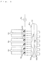
- Figure 1(a) is a side view of a schematic internal construction, of a heat exchanging apparatus of the present invention.
- Figure 1(b) is a front view of a schematic internal construction, of a heat exchanging apparatus on the present invention.
- Figure 2 is a longitudinal section view of a gas-liquid separator.
- Figure 3 is a perspective view of a plate-fin heat exchanger.
- Figure 4 is a block diagram of a conventional heat exchanging apparatus and Figure 5 is a block diagram of a conventional heat exchanging apparatus too.
- a heat exchanging apparatus of the present invention with reference to Figure 1 has a plurality of plate-fin heat exchangers 1 in the hollow body 2.
- the plate-fin heat exchanger 1, as shown in Figure 3, has a construction where corrugated fins 18 and plates 19 are laminated alternately and fluid path and refrigerant path are alloted alternately between each the plates 19 so as to put the fluid to be cooled in touch with the refrigerants through plates 9. Heat is transferred through corrugation fins 18 and plates 19.
- each plate-fin heat exchanger 1 has three kinds of passages. High pressured refrigerants flows through the first passage, and low pressured refrigerants flows through the second passage.
- the high pressured refrigerants is supplied into the first passage through a first pipe 4 which is connected to the top end of the first passage as shown in Figure 1.
- the low pressured refrigerants goes out the second passage through a second pipe 5 which is connected to the top end of the second passage.
- the high pressured refrigerants goes down through the first passage in the plate-fin heat exchanger 1, and the low pressured refrigerants goes up through the second passage in the plate-fin heat exchanger 1.
- the fluid to be cooled is supplied into the third passage through a third pipe 6 which is connected to the top end of the third passage.
- the fluid to have been cooled by heat exchanging goes out the third passage through a fourth pipe 7 which is connected to the bottom end of the third passage.
- the bottom end of the first passage is connected to a flash valve through a fifth pipe 8 which collects the refrigerants and runs along to the wall of plate-fin heat exchangers 1.
- the flash valve which is not shown in Figure 1 is connected to a gas-liquid separator 10 through a sixth pipe 9 which collects the refrigerants and runs along a wall of the plate-fin heat exchangers 1.
- the above gas-liquid separator 10 comprises a horizontally H-letter shaped type of a tank. And the wall of the plate-fin heat exchangers 1 and a plane including the H-letter of the tank are in parallel with each other.
- the gas-liquid separator 10 as illustrated in Figure 2, consists of an upper accommodation portion 10a, an intermediate accommodation portion 10b and a lower accommodation portion 10c.
- the upper accommodation portion 10a which is a hollow cylinder laid in horizontal direction both of which ends are airtightly sealed.
- An injection material 11 having many injection holes 11a is provided in the upper accommodation portion 10a.
- the injection material 11 is connected to the sixth pipe 9 which is jointed to the upper accommodation portion 10a of the gas-liquid separator 10.
- the liquid of the refrigerants come out the above-said flash valve is discharged into the upper accommodation portion 10a.
- a seventh pipe 15 is also connected to the upper accommodation portion 10a.
- Other kinds of the refrigerants go through the seventh pipe 15 into the upper accommodation portion 10a under the condition that gas and liquid phases are mixed, which have different components from one going through the sixth pipe 9 into.
- the center position of the upper accommodation portion 10a is connected to a top ends of the intermediate accommodation portion 10b which is a vertical hollow cylinder.
- the bottom end of the intermediate accommodation portion 10b is connected to the lower accommodation portion 10c which is a hollow cylinder laid in horizontal direction both of which ends are airtightly sealed.
- the intermediate accommodation portion 10b connects the upper accommodation portion 10a to the lower accommodation portion 10c so that the refrigerants can flow while forming H-letter in horizontal direction.
- the gas-liquid separator 10 handles different kinds of the refrigerants supplied from the seventh pipe 15 and the injection material 11 as follows. Both liquid of the refrigerants are accommodate at the the lower accommodation portion 10c after mixing in the intermediate accommodation portion 10b. On the other hand, both gas of the refrigerants are mixed and accommodate at the upper accommodation portion 10a.
- the gas-liquid separator 10 can separate the gas of the refrigerants from the liquid of the refrigerants with uniformity as respect to components respectively.
- a eighth pipes 13 are connected to the upper accommodation portion 10a and a ninth pipes 12 are connected to the lower accommodation portion 10c. These pipes 13 and 12 are connected to unillustrated mixers which are provided in the plate-fin heat exchangers to each. These pipes 13 and 12 distribute gas and liquid of the refrigerants to the mixers respectively. After mixing gas with liquid of the refrigerants, the mixers send them to the passages in the plate-fin heat exchangers 1.
- first pipe 4 and the second pipe 5 are connected to each of the plurality of the plate-fin heat exchangers 1 so that the plurality of the plate-fin heat exchangers 1 are united into one.
- These plate-fin heat exchangers 1 are fixed on the designed position of the hollow body 2 after, the gas-liquid separator 10 is set parallel to the wall of the plate-fin heat exchangers.
- each one ends of the pipes such as a the sixth pipes 9 or the seventh pipe 15 is connected to the gas-liquid separator 10 and each other ends of them is connected to the plate-fin heat exchangers or the un-illustrated flash valve.
- the gas-liquid separator 10 consists of the horizontally H-letter shaped tank, and also the upper accommodation portion 10a is a hollow cylinder horizontally installed. Therefore, as illustrated in Figure 2, it is possible to connect the pipes 9, 13 and 15 to the upper accommodation portion 10a in one plane including the H-letter of the tank even if there are a lot of the pipes 9, 13 and 15. Finally, the pipes which are attached to the gas-liquid separator 10 can be placed in the same plane as including the gas-liquid separator 10 which is parallel to the wall of the plate-fin heat exchangers.
- the heat exchanging apparatus of the present invention comprises the gas-liquid separator 10 and the plate-fin heat exchangers 1 in the hollow body where each plate-fin heat exchanger 1 exchanges heat between the refrigerants and the fluid to be cooled, and also the fluid and the refrigerants flow about in a hollow body through the pipes (the first pipe 4 and so on) while gas and liquid of the refrigerants are repeatedly separated and mixed for exchange heat between the refrigerants and the fluid to be cooled such as a natural gas.
- the gas-liquid separator 10 is characterized by comprising the upper accommodation portion 10a and the lower accommodation portion 10c which are the hollow cylinders laid in horizontal direction both of which ends are airtightly sealed and the intermediate accommodation portion 10b which connects the the upper accommodation portion 10a to the lower accommodation portion 10c so that the refrigerants may flow through while forming H-letter in horizontal direction.
- the distribution pipes from the gas-liquid separator 10 can be connect directly to plate-fin heat exchangers 1 without a common pipe since the gas-liquid separator 10 is set longer horizontally in comparison with a vertically cylindrical tank.
- Comprising the intermediate accommodation portion 10b enables the fluctuation range of the liquid level in operation to become larger in comparison with a horizontally cylindrical tank having the same diameter, so that, the operation of the present heat exchanging apparatus is improved. Further, when two or more different kinds of the refrigerants are supplied into the upper accommodation portion 10a, their liquid phase are mixed with each other while they go through the intermediate accommodation portion 10b, so that, it is possible to distribute the liquid phase with the uniformity of composition in comparison with a horizontally cylindrical tank.
- the above example of the present invention shows only one intermediate accommodation portion 10b which connects the upper accommodation portion 10a to the lower accommodation portion 10c so that the refrigerants may go through.
- the intermediate accommodation portion 10b is not limited to be single in number.
- a plurality of intermediate accommodation portions 10b are applicable. Efficiency of a Mixing in case of a plurality of intermediate accommodation portions 10b applied may be inferior to one in case of the single intermediate accommodation portion 10b.
- the present invention of the heat exchanging apparatus refrigerats the fluid to be cooled while the fluid and the refrigerant flow about in the hollow body through pipes so that the gas and liquid of the refrigerants may be repeatedly separated and mixed for exchange heat between the fluid and the refrigerants.
- the present heat exchanging apparatus comprises the plurality of plate-fin heat exchangers for exchanging heat between the refrigerants and the fluid, and the horizontally H-letter shaped type of gas-liquid separator in the hollow body.
- the gas-liquid separator includes the upper and lower accommodation portions which are hollow cylinders laid in horizontal direction both of which ends are airtightly sealed, and the intermediate accommodation portion which connects the upper accommodation portion to the lower accommodation portion so that the refrigerants may go through while forming H-letter.
- the present invention can not only reduce its diameter than the vertically cylindrical tank but also simplify the pipe system for distributing the separated gas and liquid. In addition to that, it can not only get the wider fluctuation range of the liquid level in comparison with the vertically cylindrical tank but also efficiently mix several kinds of liquids having different composition by working of the intermediate accommodation portion.
- the horizontally H-letter shaped type of gas-liquid separator and the plurality of plate-fin heat exchangers having a larger heat exchange performance per volume, it is possible to minimizing a volume of the hollow body keeping the same performance for separating and mixing gas and liquid.
- the present invention is suitable as the heat exchanging apparatus which equips the heat exchangers and the horizontal type of the gas-liquid separator in a hollow body, which enables the hollow body to become small size, enables to obtain a fluctuation range of a liquid level without any problems of operation, and enables to mix up two or more kinds of the refrigerants sufficiently and distribute the uniformly mixed refrigerants to the plurality of heat exchangers.
Landscapes
- Engineering & Computer Science (AREA)
- Physics & Mathematics (AREA)
- Mechanical Engineering (AREA)
- Thermal Sciences (AREA)
- General Engineering & Computer Science (AREA)
- Chemical & Material Sciences (AREA)
- Chemical Kinetics & Catalysis (AREA)
- General Chemical & Material Sciences (AREA)
- Oil, Petroleum & Natural Gas (AREA)
- Heat-Exchange Devices With Radiators And Conduit Assemblies (AREA)
- Separation By Low-Temperature Treatments (AREA)
Applications Claiming Priority (3)
| Application Number | Priority Date | Filing Date | Title |
|---|---|---|---|
| JP6064665A JPH07243760A (ja) | 1994-03-07 | 1994-03-07 | 熱交換装置 |
| JP64665/94 | 1994-03-07 | ||
| PCT/JP1995/000360 WO1995024595A1 (fr) | 1994-03-07 | 1995-03-07 | Appareil echangeur de chaleur |
Publications (3)
| Publication Number | Publication Date |
|---|---|
| EP0697573A1 true EP0697573A1 (fr) | 1996-02-21 |
| EP0697573A4 EP0697573A4 (fr) | 1996-04-24 |
| EP0697573B1 EP0697573B1 (fr) | 1998-07-22 |
Family
ID=13264734
Family Applications (1)
| Application Number | Title | Priority Date | Filing Date |
|---|---|---|---|
| EP95910750A Expired - Lifetime EP0697573B1 (fr) | 1994-03-07 | 1995-03-07 | Appareil echangeur de chaleur |
Country Status (5)
| Country | Link |
|---|---|
| US (1) | US5597037A (fr) |
| EP (1) | EP0697573B1 (fr) |
| JP (1) | JPH07243760A (fr) |
| DE (1) | DE69503579T2 (fr) |
| WO (1) | WO1995024595A1 (fr) |
Cited By (2)
| Publication number | Priority date | Publication date | Assignee | Title |
|---|---|---|---|---|
| NL1018672C2 (nl) * | 2001-07-31 | 2003-02-06 | Stichting Energie | Stelsel voor het strippen en rectificeren van een fluïdummengsel. |
| RU2200917C2 (ru) * | 1997-01-24 | 2003-03-20 | Модайн Мэньюфэктуринг Компани (Э Висконсин Корпорэйшн) | Испаритель-конденсатор для теплового насоса |
Families Citing this family (10)
| Publication number | Priority date | Publication date | Assignee | Title |
|---|---|---|---|---|
| JP2005134009A (ja) * | 2003-10-29 | 2005-05-26 | Mitsubishi Electric Corp | 冷媒分配器 |
| US20090258750A1 (en) * | 2008-04-15 | 2009-10-15 | Ziech James F | Vehicle differential |
| JP2013528778A (ja) * | 2010-06-18 | 2013-07-11 | レール・リキード−ソシエテ・アノニム・プール・レテュード・エ・レクスプロワタシオン・デ・プロセデ・ジョルジュ・クロード | 熱交換器ユニット |
| US20130277021A1 (en) * | 2012-04-23 | 2013-10-24 | Lummus Technology Inc. | Cold Box Design for Core Replacement |
| US10436483B2 (en) * | 2012-08-30 | 2019-10-08 | Shaoming Yu | Heat exchanger for micro channel |
| CN104315758B (zh) * | 2014-10-20 | 2016-09-07 | 广东美的制冷设备有限公司 | 空调器及其平行流蒸发器 |
| CN105651086B (zh) * | 2016-02-26 | 2017-08-11 | 中国海洋石油总公司 | 一种能用于浮式平台的板翅式换热器 |
| CN110945300B (zh) * | 2017-08-03 | 2022-07-22 | 三菱电机株式会社 | 制冷剂分配器、热交换器及制冷循环装置 |
| WO2019055660A1 (fr) * | 2017-09-14 | 2019-03-21 | Chart Energy & Chemicals, Inc. | Séparateur de collecteur de sortie de condenseur de fluide frigorigène mixte |
| US12287145B2 (en) * | 2020-03-13 | 2025-04-29 | Air Products And Chemicals, Inc. | Heat exchanger apparatus, manifold arrangement for a heat exchanger apparatus, and methods relating to same |
Family Cites Families (10)
| Publication number | Priority date | Publication date | Assignee | Title |
|---|---|---|---|---|
| US3874184A (en) * | 1973-05-24 | 1975-04-01 | Phillips Petroleum Co | Removing nitrogen from and subsequently liquefying natural gas stream |
| US4157904A (en) * | 1976-08-09 | 1979-06-12 | The Ortloff Corporation | Hydrocarbon gas processing |
| US4172711A (en) * | 1978-05-12 | 1979-10-30 | Phillips Petroleum Company | Liquefaction of gas |
| US4430103A (en) * | 1982-02-24 | 1984-02-07 | Phillips Petroleum Company | Cryogenic recovery of LPG from natural gas |
| FR2571129B1 (fr) * | 1984-09-28 | 1988-01-29 | Technip Cie | Procede et installation de fractionnement cryogenique de charges gazeuses |
| US4687499A (en) * | 1986-04-01 | 1987-08-18 | Mcdermott International Inc. | Process for separating hydrocarbon gas constituents |
| JPH0296569U (fr) * | 1989-01-18 | 1990-08-01 | ||
| JP2555307Y2 (ja) * | 1990-04-02 | 1997-11-19 | 三菱重工業株式会社 | ヒートポンプ冷凍サイクル |
| DE4036854C1 (fr) * | 1990-11-19 | 1992-05-21 | Thermal-Werke, Waerme-, Kaelte-, Klimatechnik Gmbh, 6832 Hockenheim, De | |
| JPH0749329Y2 (ja) * | 1991-10-21 | 1995-11-13 | ダイキン工業株式会社 | 冷凍装置の分流器 |
-
1994
- 1994-03-07 JP JP6064665A patent/JPH07243760A/ja active Pending
-
1995
- 1995-03-07 DE DE69503579T patent/DE69503579T2/de not_active Expired - Lifetime
- 1995-03-07 US US08/532,798 patent/US5597037A/en not_active Expired - Lifetime
- 1995-03-07 EP EP95910750A patent/EP0697573B1/fr not_active Expired - Lifetime
- 1995-03-07 WO PCT/JP1995/000360 patent/WO1995024595A1/fr not_active Ceased
Cited By (4)
| Publication number | Priority date | Publication date | Assignee | Title |
|---|---|---|---|---|
| RU2200917C2 (ru) * | 1997-01-24 | 2003-03-20 | Модайн Мэньюфэктуринг Компани (Э Висконсин Корпорэйшн) | Испаритель-конденсатор для теплового насоса |
| NL1018672C2 (nl) * | 2001-07-31 | 2003-02-06 | Stichting Energie | Stelsel voor het strippen en rectificeren van een fluïdummengsel. |
| WO2003011418A1 (fr) * | 2001-07-31 | 2003-02-13 | Stichting Energieonderzoek Centrum Nederland | Systeme de stripage et de rectification d'un melange fluide |
| US7111673B2 (en) | 2001-07-31 | 2006-09-26 | Stichting Energieonderzoek Centrum Nederland | System for stripping and rectifying a fluid mixture |
Also Published As
| Publication number | Publication date |
|---|---|
| EP0697573A4 (fr) | 1996-04-24 |
| US5597037A (en) | 1997-01-28 |
| WO1995024595A1 (fr) | 1995-09-14 |
| DE69503579T2 (de) | 1998-12-17 |
| JPH07243760A (ja) | 1995-09-19 |
| DE69503579D1 (de) | 1998-08-27 |
| EP0697573B1 (fr) | 1998-07-22 |
Similar Documents
| Publication | Publication Date | Title |
|---|---|---|
| EP0697573B1 (fr) | Appareil echangeur de chaleur | |
| US5385203A (en) | Plate fin heat exchanger built-in type multi-stage thermosiphon | |
| US6179051B1 (en) | Distributor for plate heat exchangers | |
| RU2296616C2 (ru) | Устройство для обмена и/или реакции между текучими средами | |
| US6769269B2 (en) | Multistage gas and liquid phase separation condenser | |
| US6244333B1 (en) | Corrugated folded plate heat exchanger | |
| DE60202611T2 (de) | System zum strippen und rektifizieren eines fluidgemisches | |
| CN1636127A (zh) | 具有整体热交换器的沉入式蒸发器 | |
| JPH09126677A (ja) | 蓄熱装置動作方法、蓄熱装置及び冷却装置 | |
| EP1006323A1 (fr) | Reservoir recepteur | |
| US6340052B1 (en) | Heat exchanger | |
| CN103256759A (zh) | 热交换器 | |
| CN101194133A (zh) | 满液式蒸发器 | |
| US20010040027A1 (en) | Heat exchanger with fluid-phase change | |
| US20190264983A1 (en) | Vertical tube heat exchanger and method for exchanging heat | |
| US7096930B2 (en) | Heat exchanger for refrigerant cycle | |
| EP0797067A1 (fr) | Dispositif pour la distribution uniforme du fluide vers une pluralité de tubes d'un échangeur de chaleur | |
| JPH0642886A (ja) | 特に非共沸性作用流体によって運転される混成熱ポンプのための熱交換器装置 | |
| JP3214272B2 (ja) | 凝縮器 | |
| JP2001343174A (ja) | 分配流入器付き蒸発器 | |
| IL300315B2 (en) | Compact heat exchanger | |
| CN219511373U (zh) | 混流器、换热器及气体调节设备 | |
| JP2927006B2 (ja) | 熱交換器 | |
| JPH04174296A (ja) | 凝縮器 | |
| CN219797580U (zh) | 一种冷凝器 |
Legal Events
| Date | Code | Title | Description |
|---|---|---|---|
| PUAI | Public reference made under article 153(3) epc to a published international application that has entered the european phase |
Free format text: ORIGINAL CODE: 0009012 |
|
| 17P | Request for examination filed |
Effective date: 19951206 |
|
| AK | Designated contracting states |
Kind code of ref document: A1 Designated state(s): DE FR GB |
|
| A4 | Supplementary search report drawn up and despatched | ||
| AK | Designated contracting states |
Kind code of ref document: A4 Designated state(s): DE FR GB |
|
| 17Q | First examination report despatched |
Effective date: 19970414 |
|
| GRAG | Despatch of communication of intention to grant |
Free format text: ORIGINAL CODE: EPIDOS AGRA |
|
| GRAG | Despatch of communication of intention to grant |
Free format text: ORIGINAL CODE: EPIDOS AGRA |
|
| GRAH | Despatch of communication of intention to grant a patent |
Free format text: ORIGINAL CODE: EPIDOS IGRA |
|
| GRAH | Despatch of communication of intention to grant a patent |
Free format text: ORIGINAL CODE: EPIDOS IGRA |
|
| GRAA | (expected) grant |
Free format text: ORIGINAL CODE: 0009210 |
|
| AK | Designated contracting states |
Kind code of ref document: B1 Designated state(s): DE FR GB |
|
| REF | Corresponds to: |
Ref document number: 69503579 Country of ref document: DE Date of ref document: 19980827 |
|
| ET | Fr: translation filed | ||
| PLBE | No opposition filed within time limit |
Free format text: ORIGINAL CODE: 0009261 |
|
| STAA | Information on the status of an ep patent application or granted ep patent |
Free format text: STATUS: NO OPPOSITION FILED WITHIN TIME LIMIT |
|
| 26N | No opposition filed | ||
| REG | Reference to a national code |
Ref country code: GB Ref legal event code: IF02 |
|
| REG | Reference to a national code |
Ref country code: GB Ref legal event code: 746 Effective date: 20031022 |
|
| REG | Reference to a national code |
Ref country code: FR Ref legal event code: D6 |
|
| PGFP | Annual fee paid to national office [announced via postgrant information from national office to epo] |
Ref country code: FR Payment date: 20140311 Year of fee payment: 20 |
|
| PGFP | Annual fee paid to national office [announced via postgrant information from national office to epo] |
Ref country code: GB Payment date: 20140305 Year of fee payment: 20 |
|
| PGFP | Annual fee paid to national office [announced via postgrant information from national office to epo] |
Ref country code: DE Payment date: 20140417 Year of fee payment: 20 |
|
| REG | Reference to a national code |
Ref country code: DE Ref legal event code: R071 Ref document number: 69503579 Country of ref document: DE |
|
| REG | Reference to a national code |
Ref country code: GB Ref legal event code: PE20 Expiry date: 20150306 |
|
| PG25 | Lapsed in a contracting state [announced via postgrant information from national office to epo] |
Ref country code: GB Free format text: LAPSE BECAUSE OF EXPIRATION OF PROTECTION Effective date: 20150306 |