EP0697601A2 - Equipement de test de sécurité pour plaque de circuit imprimé - Google Patents
Equipement de test de sécurité pour plaque de circuit imprimé Download PDFInfo
- Publication number
- EP0697601A2 EP0697601A2 EP95305711A EP95305711A EP0697601A2 EP 0697601 A2 EP0697601 A2 EP 0697601A2 EP 95305711 A EP95305711 A EP 95305711A EP 95305711 A EP95305711 A EP 95305711A EP 0697601 A2 EP0697601 A2 EP 0697601A2
- Authority
- EP
- European Patent Office
- Prior art keywords
- printed circuit
- circuit board
- safety test
- test equipment
- parts
- Prior art date
- Legal status (The legal status is an assumption and is not a legal conclusion. Google has not performed a legal analysis and makes no representation as to the accuracy of the status listed.)
- Withdrawn
Links
Images


Classifications
-
- G—PHYSICS
- G01—MEASURING; TESTING
- G01R—MEASURING ELECTRIC VARIABLES; MEASURING MAGNETIC VARIABLES
- G01R31/00—Arrangements for testing electric properties; Arrangements for locating electric faults; Arrangements for electrical testing characterised by what is being tested not provided for elsewhere
- G01R31/28—Testing of electronic circuits, e.g. by signal tracer
- G01R31/2801—Testing of printed circuits, backplanes, motherboards, hybrid circuits or carriers for multichip packages [MCP]
- G01R31/281—Specific types of tests or tests for a specific type of fault, e.g. thermal mapping, shorts testing
Definitions
- This invention relates to a safety test equipment that performs automatically a number of safety tests to diagnose any defects in designing printed circuit boards.
- the printed circuit boards even though they are not particularly problematical when used under normal conditions as products with electrical devices mounted, are compelled to undergo the safety tests based on the safety standards to see if they remain safe against the defects arising in the designing, that is, when interpart and/or interpattern short-circuits are enforced.
- This invention relates more particularly to an equipment that can perform automatically several safety tests all by itself.
- the safety test of the printed circuit board with electrical devices mounted includes mainly the interpart short-circuit, spacing and interpattern short-circuit tests.
- the subjects of said short-circuit test between the parts are such parts that are made to act at a fixed voltage or higher. Short-circuit is caused to occur between the terminals of said parts to see if there be any fuming or firing produced and, at the same time, to verify possible existence of two or more pieces of parts that are heated red.
- the spacing test is intended to check if the distance between the patterns of the printed circuit boards satisfies the specified insulating clearance.
- the purpose of the short-circuit test between the patterns is to check the existence of fuming and/or firing by causing a short-circuit to be produced between such patterns as have not turned out to meet the prescribed insulating distance as a result of said spacing test.
- FIGURE 1 is a block diagram that shows an example of the safety test equipment for printed circuit boards according to this invention.
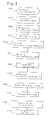
- FIGURE 2 is a flow chart of an interpart short-circuit test by the tester according to this invention.
- FIGURE 3 is another flow chart that shows the automatic short-circuit test between the parts and patterns by the tester of this invention.
- FIGURE 4 is yet another flow chart that shows the spacing test using the tester according to this invention.
- FIGURE 5 represents another flow chart that illustrates the interpattern short-circuit test using the tester by this invention.
- the safety test equipment for printed circuit board by this invention is provided with a robot 2 functioning as an automatic tester that receives a printed circuit board 1 to be tested.
- the robot 2 has a photosensor 3, a flame sensor 4, an infrared sensor 20, and a current sensor 21, all intended to monitor the test results of said printed circuit board 1 by several differing means.
- the photosensor 3 for distinguishing any abnormality of display unit that monitors the operation of the printed circuit board 1 and other subjects to be tested, including CRT, consists of a CdS, a phototransistor, a photodiode, and so forth.
- the flame sensor 4 is to detect possible ignition, while the infrared sensor 20 is used to detect possible red heat.
- the current sensor 21 is intended to detect the electric current that flows through the parts and the patterns.
- the fuming sensor 6 to detect any fuming comprises a CCD camera.
- the photosensor 3, the flame sensor 4, the infrared sensor 20, and the current sensor 21 are connected to a personal computer 8 via a switch box 5.
- the fuming sensor 6, on the other hand, is linked directly with the personal computer 8.
- a keyboard 10 Connected to the personal computer 8 are a keyboard 10, a CAD terminal 15, a television set 11 for displaying pictures, a printer 12, and finally a robot controller 13, which is connected with the robot 2.
- a power supply control unit 22 that controls the power supply of the printed circuit board 1 in order for testing
- a probe drive unit 23 that drives the probe 14
- a relay drive unit 24 that drives a relay 16 for opening/closing the probe
- an abnormality display drive unit 25 that drives the abnormality display 17 by means of light, sound and the like to alarm the abnormality.
- the printed circuit board 1 is fixed on the rectangular coordinate type robot 2 as an automatic tester for testing such particular parts in the board 1 that will be made to act at the prescribed voltage or higher. Together with the robot 2, the printed circuit board 1 is removed up to a fixed position on a plane. Projected just under the printed circuit 1 thus displaced to the fixed position are two probes 14 to short-circuit between the two terminals of the part within the printed circuit board 1. Then the existence of the fume and/or fire is examined as well as possible red heating of two or more pieces of parts.
- FIGURES 2 and 3 are the flow charts of the interpart short-circuit tests by the above procedures.
- the stage ST1 registers the data that includes the part symbols, pin numbers, pin position coordinates (X, Y), outside dimensions of the printed circuit boards, and pattern data (starting points, end points, line thickness, line types (circles, straight lines, circular arcs, etc.)).
- the short-circuit combinations are automatically made in terms of the part symbols and pin numbers, setting, for example, such conditions as resistance (1-2 pins), capacitor (1-2 pins), transistor (1-2 pins, 2-3 pins, and 1-3 pins), and IC (power supply, ground, etc.).
- ST4 stage will check the operation of the switch box 5, and if any abnormality is detected at the level of this box, the test will stop at ST22.
- ST5 stage will measure the normal value before the short-circuit at the position considered to be faulty.
- the voltage will be measured at ST8, and the resistance value, at ST9.
- ST10 will calculate the power consumption based on these measurements.
- the parts will be rearranged depending upon their power consumption, in the priority order of their testing, for instance, in the increasing or decreasing order of the power intensity.
- the robot 2 will be displaced to make the probe enter into contact with the fixed position of the part.
- the picture under normal conditions for detection of fuming will be input at the stage ST13.
- the relay 16 for short-circuit will be put on at the stage ST14.
- ST15 is the stage where the short-circuit current will be measured.
- the timer will start, at ST23, with 10 minutes if the current is 1A or higher, and with 5 minutes if it is less than 1A for example, in order to judge the possible existence of fume at ST17.
- the abnormality display unit 17 will announce the abnormality by way of alert sound and light of the lamp, for instance, using at ST50 a speech synthesis device.
- stage ST20 If the timeover is found out at the foregoing stage ST20, the operation of the switch box 5 will be checked at ST25; if there is no abnormality found, the stage ST12 will be returned to and the robot 2 will be removed to proceed to the checking of the following part and make the probe come in contact with the position of the next part.
- the spacing test is intended to measure and confirm if the distance between the patterns of the printed circuit board satisfies the prescribed insulating clearance.
- first retrieved are any adjoining patterns out of the printed circuit board information given beforehand in the personal computer by way of the communication with the CAD terminal 15.
- the printed circuit boardl is displaced on a plane together with the robot 2.
- the two probes 14 are projected just under the adjoining patterns in the printed circuit board 1 to measure the potential difference between said adjoining patterns by means of such measuring apparatus 7 as an oscilloscope connected to said two probes 14.
- the potential difference thus measured will be transferred to the personal computer 8, which will convert the difference into as much distance to be stored in the memory and displayed on the monitor 9.
- FIGURE 4 represents the flow diagram of the spacing test following the procedures as above.
- INS insert
- INS insert
- INS insert
- X pin numbers
- Y pin position coordinates
- outside dimensions of the board and the data relative to the patterns (supporting point, end point, line thickness, line type (circle, straight line, circular arc, etc.)).
- the region to be tested is set at ST35, while at ST36 margins for production dispersions will be set in terms of such safety standards as UL, CSA and TUV.
- pattern numbering is conducted, and continuous patterns are calculated out based on the pattern data to automatically assign the pattern numbers.
- the spacing test is then conducted at ST 42 to ensure, by calculation, that the distance between patterns corresponding to the voltage is secured, and any location is detected that cannot secure the distance.
- the interpattern short testing will be performed.
- short-circuit is made for prescribed time between the patterns that do not meet the fixed insulating clearance by means of the relay for short-circuit 16 connected to said probes 14 to see the existence of fuming and firing.
- FIGURE 5 we attempt to explain the procedures of this interpattern short-circuit testing.
- the interpattern short-circuit test will start at the stage ST60.
- a CCD camera is used as the fuming sensor 6, and the background for photographing shall be uniform, blackout curtain, black in level. Any fuming shall be identified by light then.
- the data of the images photographed by the fuming sensor 6 is stored in the work area of the buffer memory of the personal computer 8, and compared with the image data of the black-leveled blackout curtain as background to discriminate the differential results. For instance, the luminance will be divided into 0 to 256 gradations with 50 as threshold. If a gradation higher than 50 is found out in any portion of the image data, that portion will be assigned as high luminance part. Provided however that the neighboring portion of level 50 must be withdrawn from the evaluation because there a possibility exists that the luminance may vary in a delicate fashion. If any luminance exceeding the threshold 50 comes out from the picture, the subject of the evaluation, the image data will be input once again for comparison purpose. When said differential luminance is detected with prescribed frequency, it will be judged as fuming.
- the screen of the monitor 9 will display a wide variety of defects. For instance, such a dynamic information as "The resistance R10 in the circuit is 1.06k ⁇ , which is relatively high when compared with the normal value,” will be displayed as “R10, 1.06k ⁇ , H,” while the information that " There exists a short-circuit at the positions identified as position referential numbers 100 and 102" will be displayed as "Short, 100, 102.”
Landscapes
- Engineering & Computer Science (AREA)
- Computer Hardware Design (AREA)
- Microelectronics & Electronic Packaging (AREA)
- General Engineering & Computer Science (AREA)
- Physics & Mathematics (AREA)
- General Physics & Mathematics (AREA)
- Tests Of Electronic Circuits (AREA)
- Testing Of Short-Circuits, Discontinuities, Leakage, Or Incorrect Line Connections (AREA)
- Testing Electric Properties And Detecting Electric Faults (AREA)
- Alarm Systems (AREA)
Applications Claiming Priority (2)
| Application Number | Priority Date | Filing Date | Title |
|---|---|---|---|
| JP195725/94 | 1994-08-19 | ||
| JP19572594A JP3163909B2 (ja) | 1994-08-19 | 1994-08-19 | 安全試験の自動化装置 |
Publications (2)
| Publication Number | Publication Date |
|---|---|
| EP0697601A2 true EP0697601A2 (fr) | 1996-02-21 |
| EP0697601A3 EP0697601A3 (fr) | 1997-03-05 |
Family
ID=16345930
Family Applications (1)
| Application Number | Title | Priority Date | Filing Date |
|---|---|---|---|
| EP95305711A Withdrawn EP0697601A3 (fr) | 1994-08-19 | 1995-08-16 | Equipement de test de sécurité pour plaque de circuit imprimé |
Country Status (5)
| Country | Link |
|---|---|
| US (1) | US5696450A (fr) |
| EP (1) | EP0697601A3 (fr) |
| JP (1) | JP3163909B2 (fr) |
| CA (1) | CA2156343A1 (fr) |
| TW (1) | TW297097B (fr) |
Cited By (5)
| Publication number | Priority date | Publication date | Assignee | Title |
|---|---|---|---|---|
| DE102004019475A1 (de) * | 2004-04-22 | 2005-11-17 | Daimlerchrysler Ag | Anordnung und Verfahren zur Detektion und Lokalisierung von Kurzschlüssen in Membran-Elektroden-Anordnungen |
| FR2957423A1 (fr) * | 2010-03-09 | 2011-09-16 | Peugeot Citroen Automobiles Sa | Procede de mesure d'un mode de defaillance de composant sensible |
| DE10393237B4 (de) * | 2002-09-06 | 2013-06-06 | General Motors Corp. (N.D.Ges.D. Staates Delaware) | Verfahren zum Detektieren elektrischer Defekte in Membranelektrodenanordnungen |
| CN108490865A (zh) * | 2018-04-23 | 2018-09-04 | 安徽方瑞电气科技有限公司 | 一种自动化仪器控制系统及其控制方法 |
| CN114071858A (zh) * | 2020-07-31 | 2022-02-18 | 牧德科技股份有限公司 | 电路板的电性测试方法 |
Families Citing this family (11)
| Publication number | Priority date | Publication date | Assignee | Title |
|---|---|---|---|---|
| DE19700505A1 (de) * | 1997-01-09 | 1998-07-16 | Atg Test Systems Gmbh | Verfahren zum Prüfen von Leiterplatten |
| AU2727401A (en) | 1999-12-15 | 2001-06-25 | Introbotics Corporation | Automated domain reflectometry testing system |
| US6798229B2 (en) * | 2000-05-11 | 2004-09-28 | Brian D. Butler | Wide-bandwidth coaxial probe |
| RU2377585C1 (ru) * | 2008-04-14 | 2009-12-27 | Общество с ограниченной ответственностью "2ПR" (ООО "2ПR") | Автоматизированная система контроля монтажа, параметров электрических цепей и диагностики неисправностей сложных устройств электроаппаратуры и токораспределительных сетей |
| US20100070273A1 (en) * | 2008-09-17 | 2010-03-18 | Honeywell International Inc. | Speech synthesis and voice recognition in metrologic equipment |
| JP5391869B2 (ja) * | 2009-06-26 | 2014-01-15 | 日本電産リード株式会社 | 基板検査方法 |
| CN102116826A (zh) * | 2009-12-30 | 2011-07-06 | 鸿富锦精密工业(深圳)有限公司 | 电子元器件引脚电压量测系统及方法 |
| CN108333500A (zh) * | 2013-10-12 | 2018-07-27 | 深圳市爱德特科技有限公司 | 一种基于ddr的测试装置 |
| KR102091712B1 (ko) * | 2018-12-13 | 2020-03-25 | (주)컨트롤웍스 | 전자제어유닛 재제조 방법 |
| CN114264977B (zh) * | 2022-01-13 | 2024-01-26 | 中山市飞鸿电器有限公司 | 一种单面印刷电路板开路和短路测试装置 |
| CN119920710B (zh) * | 2025-01-16 | 2025-09-02 | 东莞朗诚微电子设备有限公司 | 一种自动上料的集成电路封装用检测设备 |
Citations (1)
| Publication number | Priority date | Publication date | Assignee | Title |
|---|---|---|---|---|
| US3803413A (en) * | 1972-05-01 | 1974-04-09 | Vanzetti Infrared Computer Sys | Infrared non-contact system for inspection of infrared emitting components in a device |
Family Cites Families (12)
| Publication number | Priority date | Publication date | Assignee | Title |
|---|---|---|---|---|
| US4379992A (en) * | 1979-12-17 | 1983-04-12 | General Electric Company | Printed circuit board electronic tester |
| JPS56110059A (en) * | 1980-02-05 | 1981-09-01 | Toshiba Corp | Automatic inspecting device for printed wiring board |
| GB2086061B (en) * | 1980-10-13 | 1985-05-22 | Marconi Instruments Ltd | Automatic test systems |
| EP0143623A3 (fr) * | 1983-11-25 | 1987-09-23 | Mars Incorporated | Equipement de test automatique |
| US4749943A (en) * | 1984-06-11 | 1988-06-07 | Thomas Black | Automatic test system |
| IL79097A0 (en) * | 1985-06-17 | 1986-09-30 | Visionetics Corp | Automatic optical inspection of printed circuit boards |
| US4760330A (en) * | 1986-06-06 | 1988-07-26 | Northern Telecom Limited | Test system with shared test instruments |
| US4862067A (en) * | 1987-06-24 | 1989-08-29 | Schlumberger Technologies, Inc. | Method and apparatus for in-circuit testing of electronic devices |
| US4857833A (en) * | 1987-08-27 | 1989-08-15 | Teradyne, Inc. | Diagnosis of faults on circuit board |
| FR2640050B1 (fr) * | 1988-12-06 | 1991-03-29 | Bull Sa | Procede pour le controle d'une carte de circuit imprime equipee notamment le controle des composants de la carte et appareillage pour la mise en oeuvre de ce procede |
| US5469064A (en) * | 1992-01-14 | 1995-11-21 | Hewlett-Packard Company | Electrical assembly testing using robotic positioning of probes |
| US5504432A (en) * | 1993-08-31 | 1996-04-02 | Hewlett-Packard Company | System and method for detecting short, opens and connected pins on a printed circuit board using automatic test equipment |
-
1994
- 1994-08-19 JP JP19572594A patent/JP3163909B2/ja not_active Expired - Fee Related
-
1995
- 1995-08-16 CA CA002156343A patent/CA2156343A1/fr not_active Abandoned
- 1995-08-16 EP EP95305711A patent/EP0697601A3/fr not_active Withdrawn
- 1995-08-18 US US08/516,697 patent/US5696450A/en not_active Expired - Fee Related
- 1995-08-22 TW TW084108802A patent/TW297097B/zh active
Patent Citations (1)
| Publication number | Priority date | Publication date | Assignee | Title |
|---|---|---|---|---|
| US3803413A (en) * | 1972-05-01 | 1974-04-09 | Vanzetti Infrared Computer Sys | Infrared non-contact system for inspection of infrared emitting components in a device |
Cited By (7)
| Publication number | Priority date | Publication date | Assignee | Title |
|---|---|---|---|---|
| DE10393237B4 (de) * | 2002-09-06 | 2013-06-06 | General Motors Corp. (N.D.Ges.D. Staates Delaware) | Verfahren zum Detektieren elektrischer Defekte in Membranelektrodenanordnungen |
| DE102004019475A1 (de) * | 2004-04-22 | 2005-11-17 | Daimlerchrysler Ag | Anordnung und Verfahren zur Detektion und Lokalisierung von Kurzschlüssen in Membran-Elektroden-Anordnungen |
| DE102004019475B4 (de) * | 2004-04-22 | 2008-07-31 | Daimler Ag | Anordnung und Verfahren zur Detektion und Lokalisierung von Kurzschlüssen in Membran-Elektroden-Anordnungen |
| FR2957423A1 (fr) * | 2010-03-09 | 2011-09-16 | Peugeot Citroen Automobiles Sa | Procede de mesure d'un mode de defaillance de composant sensible |
| CN108490865A (zh) * | 2018-04-23 | 2018-09-04 | 安徽方瑞电气科技有限公司 | 一种自动化仪器控制系统及其控制方法 |
| CN114071858A (zh) * | 2020-07-31 | 2022-02-18 | 牧德科技股份有限公司 | 电路板的电性测试方法 |
| CN114071858B (zh) * | 2020-07-31 | 2024-08-20 | 牧德科技股份有限公司 | 电路板的电性测试方法 |
Also Published As
| Publication number | Publication date |
|---|---|
| TW297097B (fr) | 1997-02-01 |
| JP3163909B2 (ja) | 2001-05-08 |
| CA2156343A1 (fr) | 1996-02-20 |
| JPH0862290A (ja) | 1996-03-08 |
| US5696450A (en) | 1997-12-09 |
| EP0697601A3 (fr) | 1997-03-05 |
Similar Documents
| Publication | Publication Date | Title |
|---|---|---|
| EP0697601A2 (fr) | Equipement de test de sécurité pour plaque de circuit imprimé | |
| US6054865A (en) | Multiple function electrical safety compliance analyzer | |
| US7259567B2 (en) | Power tester for electrical outlets | |
| US4728898A (en) | Method and apparatus for detecting and locating faults in an AC transmission line using two indicators | |
| US6341358B1 (en) | Integrity tester for parallel signal bus | |
| US3963981A (en) | Leakage and continuity tester | |
| US6958619B2 (en) | Inspecting apparatus and inspecting method for circuit board | |
| CN107238796A (zh) | 一种用于线路板的维修测试设备 | |
| CN110554302B (zh) | 快速自动检测电路板故障的装置 | |
| CN112212458B (zh) | 一种电控箱安全控制装置、方法和电器设备 | |
| CN218956779U (zh) | 熔丝质量检测试验台 | |
| KR100519593B1 (ko) | 아이알 인서키트 테스트시스템 | |
| CN111239510A (zh) | 一种空调emc的自助测试方法及测试系统 | |
| CN118962512A (zh) | 一种电源管理单元输出异常的检测方法及系统 | |
| CN215005651U (zh) | 一种电磁兼容静电放电抗扰测试系统 | |
| CN212301767U (zh) | 一种电路板测试装置 | |
| CN109163648A (zh) | 位移测量故障检测方法及装置 | |
| CN108107379B (zh) | 一种节能灯gu灯头检测装置及方法 | |
| CN222482432U (zh) | 安检系统 | |
| KR0125596B1 (ko) | 표면결함 검사방법 및 그 장치 | |
| KR100745081B1 (ko) | 버너제어시스템의 제어카드 시험장치 및 방법 | |
| KR200307562Y1 (ko) | 발전소 가스누설경보장치카드 진단장치 | |
| GB2358466A (en) | Testing interconnections in an electronic circuit assembly by thermal conduction detection. | |
| TH10088B (th) | อุปกรณ์ทดสอบความปลอดภัยของแผ่นวงจรพิมพ์ | |
| CN117572322A (zh) | 一种监测绝缘耐压测试仪设定状态的防呆工具 |
Legal Events
| Date | Code | Title | Description |
|---|---|---|---|
| PUAI | Public reference made under article 153(3) epc to a published international application that has entered the european phase |
Free format text: ORIGINAL CODE: 0009012 |
|
| AK | Designated contracting states |
Kind code of ref document: A2 Designated state(s): DE GB |
|
| PUAL | Search report despatched |
Free format text: ORIGINAL CODE: 0009013 |
|
| AK | Designated contracting states |
Kind code of ref document: A3 Designated state(s): DE GB |
|
| 17P | Request for examination filed |
Effective date: 19970821 |
|
| STAA | Information on the status of an ep patent application or granted ep patent |
Free format text: STATUS: THE APPLICATION HAS BEEN WITHDRAWN |
|
| 18W | Application withdrawn |
Withdrawal date: 20020624 |