EP0697606A2 - Connecteur pour fibres optiques à plusieurs parties - Google Patents
Connecteur pour fibres optiques à plusieurs parties Download PDFInfo
- Publication number
- EP0697606A2 EP0697606A2 EP95202976A EP95202976A EP0697606A2 EP 0697606 A2 EP0697606 A2 EP 0697606A2 EP 95202976 A EP95202976 A EP 95202976A EP 95202976 A EP95202976 A EP 95202976A EP 0697606 A2 EP0697606 A2 EP 0697606A2
- Authority
- EP
- European Patent Office
- Prior art keywords
- optical
- optical fibre
- housing
- fibre connector
- connector
- Prior art date
- Legal status (The legal status is an assumption and is not a legal conclusion. Google has not performed a legal analysis and makes no representation as to the accuracy of the status listed.)
- Withdrawn
Links
- 239000013307 optical fiber Substances 0.000 title claims abstract description 117
- 230000003287 optical effect Effects 0.000 claims abstract description 125
- 239000004020 conductor Substances 0.000 claims abstract description 39
- 239000000463 material Substances 0.000 claims abstract description 10
- 239000002991 molded plastic Substances 0.000 claims abstract description 8
- 239000004033 plastic Substances 0.000 claims description 7
- 229920003023 plastic Polymers 0.000 claims description 7
- 239000000835 fiber Substances 0.000 claims 1
- 230000000694 effects Effects 0.000 description 10
- 230000013011 mating Effects 0.000 description 6
- 230000005540 biological transmission Effects 0.000 description 4
- 238000010276 construction Methods 0.000 description 2
Images

Classifications
-
- G—PHYSICS
- G02—OPTICS
- G02B—OPTICAL ELEMENTS, SYSTEMS OR APPARATUS
- G02B6/00—Light guides; Structural details of arrangements comprising light guides and other optical elements, e.g. couplings
- G02B6/24—Coupling light guides
- G02B6/42—Coupling light guides with opto-electronic elements
- G02B6/4201—Packages, e.g. shape, construction, internal or external details
- G02B6/4249—Packages, e.g. shape, construction, internal or external details comprising arrays of active devices and fibres
-
- G—PHYSICS
- G02—OPTICS
- G02B—OPTICAL ELEMENTS, SYSTEMS OR APPARATUS
- G02B6/00—Light guides; Structural details of arrangements comprising light guides and other optical elements, e.g. couplings
- G02B6/24—Coupling light guides
- G02B6/26—Optical coupling means
- G02B6/30—Optical coupling means for use between fibre and thin-film device
-
- G—PHYSICS
- G02—OPTICS
- G02B—OPTICAL ELEMENTS, SYSTEMS OR APPARATUS
- G02B6/00—Light guides; Structural details of arrangements comprising light guides and other optical elements, e.g. couplings
- G02B6/24—Coupling light guides
- G02B6/36—Mechanical coupling means
- G02B6/38—Mechanical coupling means having fibre to fibre mating means
- G02B6/3807—Dismountable connectors, i.e. comprising plugs
- G02B6/3873—Connectors using guide surfaces for aligning ferrule ends, e.g. tubes, sleeves, V-grooves, rods, pins, balls
- G02B6/3885—Multicore or multichannel optical connectors, i.e. one single ferrule containing more than one fibre, e.g. ribbon type
-
- G—PHYSICS
- G02—OPTICS
- G02B—OPTICAL ELEMENTS, SYSTEMS OR APPARATUS
- G02B6/00—Light guides; Structural details of arrangements comprising light guides and other optical elements, e.g. couplings
- G02B6/24—Coupling light guides
- G02B6/36—Mechanical coupling means
- G02B6/38—Mechanical coupling means having fibre to fibre mating means
- G02B6/3807—Dismountable connectors, i.e. comprising plugs
- G02B6/381—Dismountable connectors, i.e. comprising plugs of the ferrule type, e.g. fibre ends embedded in ferrules, connecting a pair of fibres
- G02B6/3825—Dismountable connectors, i.e. comprising plugs of the ferrule type, e.g. fibre ends embedded in ferrules, connecting a pair of fibres with an intermediate part, e.g. adapter, receptacle, linking two plugs
-
- G—PHYSICS
- G02—OPTICS
- G02B—OPTICAL ELEMENTS, SYSTEMS OR APPARATUS
- G02B6/00—Light guides; Structural details of arrangements comprising light guides and other optical elements, e.g. couplings
- G02B6/24—Coupling light guides
- G02B6/36—Mechanical coupling means
- G02B6/38—Mechanical coupling means having fibre to fibre mating means
- G02B6/3807—Dismountable connectors, i.e. comprising plugs
- G02B6/3833—Details of mounting fibres in ferrules; Assembly methods; Manufacture
- G02B6/3851—Ferrules having keying or coding means
-
- G—PHYSICS
- G02—OPTICS
- G02B—OPTICAL ELEMENTS, SYSTEMS OR APPARATUS
- G02B6/00—Light guides; Structural details of arrangements comprising light guides and other optical elements, e.g. couplings
- G02B6/24—Coupling light guides
- G02B6/36—Mechanical coupling means
- G02B6/38—Mechanical coupling means having fibre to fibre mating means
- G02B6/3807—Dismountable connectors, i.e. comprising plugs
- G02B6/3833—Details of mounting fibres in ferrules; Assembly methods; Manufacture
- G02B6/3865—Details of mounting fibres in ferrules; Assembly methods; Manufacture fabricated by using moulding techniques
-
- G—PHYSICS
- G02—OPTICS
- G02B—OPTICAL ELEMENTS, SYSTEMS OR APPARATUS
- G02B6/00—Light guides; Structural details of arrangements comprising light guides and other optical elements, e.g. couplings
- G02B6/24—Coupling light guides
- G02B6/36—Mechanical coupling means
- G02B6/38—Mechanical coupling means having fibre to fibre mating means
- G02B6/3807—Dismountable connectors, i.e. comprising plugs
- G02B6/389—Dismountable connectors, i.e. comprising plugs characterised by the method of fastening connecting plugs and sockets, e.g. screw- or nut-lock, snap-in, bayonet type
- G02B6/3893—Push-pull type, e.g. snap-in, push-on
Definitions
- This invention relates to multi-part optical fibre connectors for detachably optically inter-connecting end-to-end at least two flexible optical guides each comprising at least one optical fibre.
- Such multi-part optical fibre connectors essentially comprise two separately formed connector-parts, each of which is adapted to be permanently or detachably secured to one of the flexible optical guides to be optically inter-connected, and may include at least one separately formed intermediate connector-part or adaptor for optically inter-connecting two separately formed connector parts.
- each connector part of a multi-part optical fibre connector constitutes at one or each of two oppositely disposed ends of the connector-part a plug or a socket adapted to effect a detachable plug and socket connection with a socket or a plug at an end of another connector-part.
- Multi-part optical fibre connectors of this kind are widely used in optical transmission systems.
- the improved optical fibre connector-part comprises a housing in which at least one optical conductor extends between two oppositely disposed ends of the housing, at least one of said two oppositely disposed ends of the housing constituting a plug or a socket, and at least one integrated optical chip disposed within the housing and constituting at least a part of the optical conductor or of at least one of the optical conductors extending between said oppositely disposed ends of the housing.
- the housing of the improved connector-part preferably is a moulded body of plastics material and, in this case, preferably the or each integrated optical chip is at least partially encapsulated in the moulded plastics material of the housing.
- the integrated optical chip or at least one of the integrated optical chips of the improved optical fibre connector-part is so encapsulated in the plastics material of or is otherwise so disposed within the housing that the chip is intermediate of the oppositely disposed ends of the housing and is permanently optically inter-connected between end parts of the optical conductor or of at least one of the optical conductors of which it constitutes a part.
- the integrated optical chip or at least one of the integrated optical chips of the improved optical fibre connector-part may be so encapsulated in the plastics material of or may be otherwise so disposed within the housing that one side face of the chip is positioned at an end of the housing constituting a plug or socket and the chip is permanently optically connected to a part of the optical conductor or of at least one of the optical conductors extending to the other end of the housing.
- the part or parts of the or each optical conductor of the improved optical fibre connector-part not constituted by the or an integrated optical chip is or are at least one optical fibre.
- the or each integrated optical chip of the improved optical fibre connector-part may be a suitable integrated optical chip obtained from any source.
- the improved optical fibre connector-part is to constitute one end part of a multi-part optical fibre connector
- one of the two oppositely disposed ends of the housing of the improved optical fibre connector-part constitutes a plug or a socket and the other of the two oppositely disposed ends is adapted to be permanently or detachably secured to an end of at least one flexible optical guide comprising at least one optical fibre in such a way that the or each optical fibre of the guide is optically connected to the or an optical conductor of the improved optical fibre connector-part or that the or each optical fibre of the guide extends into the housing of the improved optical fibre connector-part and constitutes a part of the or an optical conductor of the connector-part.
- the end of the housing constituting a plug or a socket may also constitute at least one additional plug or socket for effecting a plug and socket connection with a socket or plug at an end of a further optical fibre connector-part.
- the or each flexible optical guide to which one end of an improved optical fibre connector-end part can be permanently or detachably secured may be an optical cable comprising a single optical fibre or comprising a plurality of optical fibres or it may be an optical fibre ribbon comprising a plurality of optical fibres arranged side-by-side with their axes lying in a substantially common plane.
- the improved optical fibre connector-part is to constitute an intermediate part of a multi-part optical fibre connector, for example an adaptor for inter-connecting by plug and socket connections two end parts of a multi-part optical fibre connector, each of two oppositely disposed ends of the housing of said intermediate improved optical fibre connector-part will constitute a plug or a socket.
- the housing of the intermediate improved optical fibre connector-part may constitute at least one additional plug or socket for effecting a plug and socket connection with a socket or plug at an end of a further optical fibre connector-part.
- the additional plug or socket or at least one of the additional plugs or sockets of the intermediate improved optical fibre connector-part may be disposed at one of the two oppositely disposed ends of the housing of the connector-part or at a position intermediate of said two oppositely disposed ends.
- the number of additional plugs or sockets constituted by the housing of the improved optical fibre connector-part will be determined by the function of the or each integrated optical chip disposed within the housing of the connector-part.
- the invention also includes an improved multi-part optical fibre connector for detachably inter-connecting end-to-end at least two flexible optical guides each comprising at least one optical fibre, at least one of the connector-parts of the multi-part optical fibre connector being an improved optical fibre connector-part substantially as hereinbefore described.
- the invention further includes a kit of parts for assembling an improved multi-part optical fibre connector as hereinbefore described, which kit of parts comprises at least two optical fibre connector-end parts each comprising a housing which at one of two oppositely disposed ends of the housing constitutes a plug or a socket and which at the other of said two oppositely disposed ends is adapted to be permanently or detachably secured to an end of at least one flexible optical guide comprising at least one optical fibre and at least one optical conductor disposed within and extending between said two oppositely disposed ends of the housing; and at least two adaptors for optically inter-connecting two end parts, each adaptor comprising a housing in which at least one optical conductor is disposed between two oppositely disposed ends of the housing, each constituting a plug or a socket, and in which at least one integrated optical chip is disposed and constitutes at least a part of said optical conductor or of at least one of said optical conductors, the integrated optical chip of each adaptor differing from the integrated optical chip of the other adaptor or of each
- At least one of the optical fibre connector-end parts of the kit of parts may have at least one integrated optical chip disposed in its housing and constituting at least a part of the optical conductor or of one of the optical conductors extending between oppositely disposed ends of the housing.
- the improved optical fibre connector-part and the improved optical fibre connector of the present invention have the important advantage that an optical transmission system of any desired configuration can be readily assembled using one or more than one improved optical fibre connector-part incorporating at least one integrated optical chip designed to effect a designed function and that an existing optical transmission system can be readily reconfigured or modified by replacing one or more than one improved optical fibre connector-part inter-connected in the system with one or more than one improved optical fibre connector-part of which the or each integrated optical chip is designed to effect a function differing from the function of the chip or chips of the connector-part being replaced.
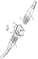
- the preferred two-part optical fibre connector comprises an optical fibre connector-part 1 having protruding from one of two oppositely disposed ends of its moulded plastics body 2 a pair of transversely spaced parallel rigid pins 3 adapted to effect plug and socket connections in a pair of transversely spaced parallel holes 13 in one of two oppositely disposed ends of the moulded plastics body 12 of an optical fibre connector-part 11.
- Encapsulated in one of the two oppositely disposed ends of the moulded body 12 of the optical fibre connector-part 11 is an end of an optical fibre ribbon cable 14 from which protrude four optical fibres 15 which are centrally disposed between the transversely spaced holes 13 and which extend to the other of the oppositely disposed ends of the body with their axes lying in the same plane as the axes of the holes.
- Encapsulated in one of the two oppositely disposed ends of the moulded body 2 of the optical fibre connector-part 1 is an end of an optical cable 4 having a single optical fibre 5 and extending between the encapsulated end of the optical cable and the other of the oppositely disposed ends of the body is an optical conductor constituted in part by the optical fibre of the optical cable and in part by an integrated optical chip 6 which is optically connected to the optical fibre and which is so encapsulated in the plastics material of the body 2 that one side face of the chip is exposed and centrally disposed between the transversely spaced rigid pins 3.
- the integrated optical chip 6 functions as a tree coupler constituting a cascaded series of Y-junctions and in the exposed side face of the chip are exposed the end faces of four optical guides whose axes lie in the same plane as the axes of the rigid pins and which are so transversely spaced apart that, when a plug and socket connection is made between the optical fibre connector-parts 1 and 11, the end faces of the optical guides and the end faces of the optical fibres 15 abut to effect optical connections therebetween.
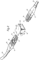
- the first preferred form of three-part optical fibre connector shown in Figure 2 comprises an optical fibre connector-part 21, an optical fibre connector-part 31 and, adapted to optically interconnect the two optical fibre connector-end parts, a mating adaptor 30.
- the optical fibre connector-end part 21 comprises a moulded plastics body 22 in one of two oppositely disposed ends of which is encapsulated an end of a multifibre optical cable 23, the other end 24 of the moulded body constituting a plug.
- Encapsulated in the plug 24 of the optical fibre connector-end part 21 is a moulded array connector in an exposed end face of which are exposed the end faces of a plurality of optical fibres optically connected to the optical fibres of the optical cable 23.
- the axes of the exposed end faces of the optical fibres of the moulded array connector lie in a substantially common plane.
- the optical fibre connector-end part 31 comprises a moulded plastics body 32 having encapsulated in one of two oppositely disposed ends an end of an optical cable 33, the other of the oppositely disposed ends of the body constituting a plug 34.
- a moulded array connector 35 is so encapsulated in the plug 34 of the optical fibre connector-end part 31 that one end face of the moulded array connector is exposed.
- Extending between the optical fibres of the optical cable 33 and the encapsulated moulded array connector 35 are a plurality of optical conductors constituted in part by optical fibres and in part by an integrated optical chip 36 encapsulated in the moulded body 32 intermediate of its ends and permanently optically connected between the optical fibres constituting the optical conductors.
- the integrated optical chip 36 functions as a star coupler incorporating a mixing region intermediate of a plurality of input points and a plurality of output points.
- the end faces of the optical fibres extending from the integrated optical chip 36 are exposed at the end face of the moulded array connector 35 with their axes lying in a substantially common plane.
- each of the plugs 24, 34 has a rib 27, 37 adapted to engage in a groove 29 in the mating adaptor 30, the arrangement being such that when the plugs 24, 34 are fully engaged in the mating adaptor the exposed end faces of the moulded array connectors 25, 35 abut with the exposed end faces of the optical fibres in axial alignment.
- each of the optical fibre connector-end parts 41 is of substantially the same construction as the optical fibre connector-end part 21 of the three-part optical fibre connector shown in Figure 2.
- the mating adaptor 50 has permanently disposed intermediate of oppositely disposed sockets of the adaptor adapted to effect plug and socket connections with the plugs 44 of the optical fibre connector end parts, an integrated optical chip 56 in each of two oppositely disposed end faces of which are exposed the end faces of a plurality of optical guides with the axes of the guides lying in a common plane.
- the integrated optical chip 56 may be designed to effect any one of the plurality of fibre-optic functions hereinbefore recited.
- the arrangement is such that, when the plugs 44 of the optical fibre connector-end parts 41 effect plug and socket connections in the sockets at the opposite ends of the mating adaptor 50, the exposed end faces of the moulded array connectors encapsulated in the plugs abut the oppositely disposed end faces of the integrated optical chip 56 with the end faces of the optical fibres of the moulded array connectors and the end faces of the optical guides of the integrated optical chip being in axial alignment.
Landscapes
- Physics & Mathematics (AREA)
- General Physics & Mathematics (AREA)
- Optics & Photonics (AREA)
- Mechanical Coupling Of Light Guides (AREA)
- Optical Couplings Of Light Guides (AREA)
Applications Claiming Priority (3)
| Application Number | Priority Date | Filing Date | Title |
|---|---|---|---|
| GB909011424A GB9011424D0 (en) | 1990-05-22 | 1990-05-22 | Multi-part optical fibre connectors |
| GB9011424 | 1990-05-22 | ||
| EP91304613A EP0458608B1 (fr) | 1990-05-22 | 1991-05-21 | Connecteur pour fibres optiques à plusieurs parties |
Related Parent Applications (1)
| Application Number | Title | Priority Date | Filing Date |
|---|---|---|---|
| EP91304613.2 Division | 1991-05-21 |
Publications (2)
| Publication Number | Publication Date |
|---|---|
| EP0697606A2 true EP0697606A2 (fr) | 1996-02-21 |
| EP0697606A3 EP0697606A3 (fr) | 1996-09-25 |
Family
ID=10676361
Family Applications (2)
| Application Number | Title | Priority Date | Filing Date |
|---|---|---|---|
| EP95202976A Withdrawn EP0697606A3 (fr) | 1990-05-22 | 1991-05-21 | Connecteur pour fibres optiques à plusieurs parties |
| EP91304613A Expired - Lifetime EP0458608B1 (fr) | 1990-05-22 | 1991-05-21 | Connecteur pour fibres optiques à plusieurs parties |
Family Applications After (1)
| Application Number | Title | Priority Date | Filing Date |
|---|---|---|---|
| EP91304613A Expired - Lifetime EP0458608B1 (fr) | 1990-05-22 | 1991-05-21 | Connecteur pour fibres optiques à plusieurs parties |
Country Status (8)
| Country | Link |
|---|---|
| EP (2) | EP0697606A3 (fr) |
| JP (1) | JPH04229810A (fr) |
| AT (1) | ATE141015T1 (fr) |
| AU (2) | AU651974B2 (fr) |
| CA (1) | CA2042985C (fr) |
| DE (1) | DE69121141T2 (fr) |
| GB (2) | GB9011424D0 (fr) |
| HK (1) | HK87295A (fr) |
Cited By (2)
| Publication number | Priority date | Publication date | Assignee | Title |
|---|---|---|---|---|
| US5737463A (en) * | 1995-12-22 | 1998-04-07 | Weiss; Roger E. | Massive parallel optical interconnect system |
| US6045270A (en) * | 1995-12-22 | 2000-04-04 | Methode Electronics, Inc. | Massive parallel optical interconnect system |
Families Citing this family (19)
| Publication number | Priority date | Publication date | Assignee | Title |
|---|---|---|---|---|
| US5414786A (en) * | 1992-10-09 | 1995-05-09 | The Furukawa Electric Co., Ltd. | Optical waveguide component with a molded resin portion having accurately aligned guide pin holes therein |
| EP0645651B1 (fr) * | 1993-03-31 | 1999-06-02 | Sumitomo Electric Industries, Ltd | Groupement de fibres optiques |
| USD354271S (en) | 1993-05-17 | 1995-01-10 | 3 Com Corporation | Fiber optic interchangeable transceiver module |
| USD353796S (en) | 1993-05-17 | 1994-12-27 | 3 Com Corporation | Fiber optic interchangeable transceiver module |
| EP0721122A1 (fr) * | 1994-12-07 | 1996-07-10 | AT&T Corp. | Dispositifs et procédés pour interconnecter des réseaux de guides de transmission optiques |
| JPH08271757A (ja) * | 1995-03-31 | 1996-10-18 | Nec Corp | 光導波路モジュールとその製造方法 |
| DE19630546C1 (de) * | 1996-07-17 | 1998-02-12 | Siemens Ag | Optisches Steckerteil und Verfahren zum Herstellen eines optischen Steckerteils |
| US5778121A (en) * | 1996-11-05 | 1998-07-07 | Itt Corporation | Connector with optic fiber terminal |
| DE19743992C1 (de) * | 1997-09-26 | 1999-06-24 | Siemens Ag | Verfahren zum Herstellen eines optoelektronischen Steckeraufnahmeelementes und optoelektronischer Stecker |
| DE29721776U1 (de) * | 1997-11-28 | 1999-04-01 | Siemens AG, 80333 München | Verbinderkörper |
| SE9704466L (sv) * | 1997-12-01 | 1999-06-02 | Ericsson Telefon Ab L M | Förbindningsorgan för optofibrer |
| US6468306B1 (en) | 1998-05-29 | 2002-10-22 | Advanced Medical Optics, Inc | IOL for inhibiting cell growth and reducing glare |
| EP0977063A1 (fr) * | 1998-07-28 | 2000-02-02 | Interuniversitair Micro-Elektronica Centrum Vzw | Socle et système pour interconnection optoélectronique et méthode de fabrication d'un tel socle et système |
| EP0977064A1 (fr) * | 1998-07-28 | 2000-02-02 | Interuniversitair Micro-Elektronica Centrum Vzw | Socle et système pour interconnection optoélectronique et méthode de fabrication d'un tel socle et système |
| US6315463B1 (en) | 1998-08-21 | 2001-11-13 | Infineon Technologies Ag | Method for production of an optoelectronic female connector element, and an optoelectronic connector |
| GB2379747B (en) | 2001-06-22 | 2003-08-27 | Bookham Technology Plc | Optical Chip with optic fibre alignment features |
| GB2401196B (en) * | 2003-05-02 | 2007-02-07 | Agilent Technologies Inc | Packaged planar lightwave circuit arrangements corresponding method of connection and component |
| ES2343614B1 (es) * | 2008-10-15 | 2011-10-03 | Nordix, S.A. | Derivador compacto de exterior para transicion horizontal / vertical de cable de fibra optica. |
| EP2710743B1 (fr) | 2011-05-17 | 2018-08-29 | Corning Research & Development Corporation | Réseau intra-bâtiment convergent |
Family Cites Families (6)
| Publication number | Priority date | Publication date | Assignee | Title |
|---|---|---|---|---|
| US4650278A (en) * | 1983-10-31 | 1987-03-17 | Northern Telecom Limited | Fiber optic access nodes |
| US4611886A (en) * | 1983-12-29 | 1986-09-16 | At&T Bell Laboratories | Integrated optical circuit package |
| JPS60200210A (ja) * | 1984-03-23 | 1985-10-09 | Matsushita Electric Works Ltd | 光結合器 |
| US4718055A (en) * | 1985-09-17 | 1988-01-05 | Siemens Aktiengesellschaft | Wave-division multiplex component for an optical network comprising monomode transmission fibers |
| DE3780802T2 (de) * | 1987-01-15 | 1993-03-04 | Philips Nv | Einrichtung mit einer planaren optischen schaltung und daran gekoppelte optische faser. |
| US5046808A (en) * | 1989-12-18 | 1991-09-10 | Litton Systems, Inc. | Integrated optics chip and method of connecting optical fiber thereto |
-
1990
- 1990-05-22 GB GB909011424A patent/GB9011424D0/en active Pending
-
1991
- 1991-05-21 GB GB9110948A patent/GB2245082B/en not_active Expired - Fee Related
- 1991-05-21 EP EP95202976A patent/EP0697606A3/fr not_active Withdrawn
- 1991-05-21 AU AU77210/91A patent/AU651974B2/en not_active Ceased
- 1991-05-21 EP EP91304613A patent/EP0458608B1/fr not_active Expired - Lifetime
- 1991-05-21 AT AT91304613T patent/ATE141015T1/de not_active IP Right Cessation
- 1991-05-21 CA CA002042985A patent/CA2042985C/fr not_active Expired - Fee Related
- 1991-05-21 DE DE69121141T patent/DE69121141T2/de not_active Expired - Fee Related
- 1991-05-22 JP JP3145243A patent/JPH04229810A/ja active Pending
-
1994
- 1994-11-11 AU AU78806/94A patent/AU687900B2/en not_active Ceased
-
1995
- 1995-06-01 HK HK87295A patent/HK87295A/xx not_active IP Right Cessation
Non-Patent Citations (1)
| Title |
|---|
| None |
Cited By (3)
| Publication number | Priority date | Publication date | Assignee | Title |
|---|---|---|---|---|
| US5737463A (en) * | 1995-12-22 | 1998-04-07 | Weiss; Roger E. | Massive parallel optical interconnect system |
| US6045270A (en) * | 1995-12-22 | 2000-04-04 | Methode Electronics, Inc. | Massive parallel optical interconnect system |
| US6276840B1 (en) | 1995-12-22 | 2001-08-21 | Stratos Lightwave, Inc. | Massive parallel optical interconnect system |
Also Published As
| Publication number | Publication date |
|---|---|
| AU687900B2 (en) | 1998-03-05 |
| CA2042985C (fr) | 2002-07-23 |
| GB2245082B (en) | 1994-09-14 |
| CA2042985A1 (fr) | 1991-11-23 |
| EP0458608B1 (fr) | 1996-07-31 |
| DE69121141D1 (de) | 1996-09-05 |
| GB2245082A (en) | 1991-12-18 |
| GB9011424D0 (en) | 1990-07-11 |
| JPH04229810A (ja) | 1992-08-19 |
| EP0458608A1 (fr) | 1991-11-27 |
| AU651974B2 (en) | 1994-08-11 |
| DE69121141T2 (de) | 1996-12-05 |
| EP0697606A3 (fr) | 1996-09-25 |
| GB9110948D0 (en) | 1991-07-10 |
| HK87295A (en) | 1995-06-09 |
| AU7721091A (en) | 1991-11-28 |
| ATE141015T1 (de) | 1996-08-15 |
| AU7880694A (en) | 1995-01-27 |
Similar Documents
| Publication | Publication Date | Title |
|---|---|---|
| US5199093A (en) | Multi-part optical fibre connectors | |
| EP0458608B1 (fr) | Connecteur pour fibres optiques à plusieurs parties | |
| US7218828B2 (en) | Optical fiber power splitter module apparatus | |
| US5216732A (en) | Optical fiber guide connection | |
| EP0307518B1 (fr) | Connecteurs à fibre optique à haute précision | |
| US5971625A (en) | Double ferrule SC connector and adapter | |
| US7156561B2 (en) | Optical connector | |
| US20140241689A1 (en) | Ganged fiber optic connector adapter modules and assemblies having reinforcement members and staggered fiber optic connector adapter ports | |
| KR970702477A (ko) | 프로그래밍이 가능한 케이블 어댑터(Programmable cable adaptor) | |
| MY132200A (en) | Duplex connector | |
| US20240411094A1 (en) | Fiber optic network systems | |
| CN218675399U (zh) | 12芯(fiber)mpo至16芯mpo转换模块 | |
| US6860642B2 (en) | Compact optical package with modular optical connector | |
| PL191206B1 (pl) | Urządzenie wtykowe dla światłowodów | |
| US6582133B2 (en) | Module and method for interconnecting optoelectronic cards | |
| US11294131B2 (en) | Waveguide shuffle blocks for optical system connectivity | |
| US5390267A (en) | Optical fiber/terminal connecting device | |
| JPS60200210A (ja) | 光結合器 | |
| CN111025491B (zh) | 一种多功能的光纤适配器 | |
| US5984533A (en) | Optical fiber connector | |
| Wagner et al. | SC-DC/SC-QC fiber optic connector | |
| JP2779187B2 (ja) | 光伝送線路切替用コネクタ | |
| CN1423446A (zh) | 可插拔光分插和复用模块 | |
| CN118043712A (zh) | 光纤网络系统 | |
| US8998504B2 (en) | User-configurable optical fiber link |
Legal Events
| Date | Code | Title | Description |
|---|---|---|---|
| PUAI | Public reference made under article 153(3) epc to a published international application that has entered the european phase |
Free format text: ORIGINAL CODE: 0009012 |
|
| 17P | Request for examination filed |
Effective date: 19951120 |
|
| AC | Divisional application: reference to earlier application |
Ref document number: 458608 Country of ref document: EP |
|
| AK | Designated contracting states |
Kind code of ref document: A2 Designated state(s): AT BE CH DE DK ES FR GB IT LI NL SE |
|
| PUAL | Search report despatched |
Free format text: ORIGINAL CODE: 0009013 |
|
| AK | Designated contracting states |
Kind code of ref document: A3 Designated state(s): AT BE CH DE DK ES FR GB IT LI NL SE |
|
| 17Q | First examination report despatched |
Effective date: 19990215 |
|
| STAA | Information on the status of an ep patent application or granted ep patent |
Free format text: STATUS: THE APPLICATION IS DEEMED TO BE WITHDRAWN |
|
| 18D | Application deemed to be withdrawn |
Effective date: 20000111 |