EP0697633A2 - Wiederverwendbarer, inverser, zwei-schichtig zusammengesetzter, organischer Photokonduktor, wobei spezifische Polymere eingesetzt werden die geeignet sind für Diffusionsbeschichtungsverfahren mit nicht chlorierten Lösungsmitteln - Google Patents
Wiederverwendbarer, inverser, zwei-schichtig zusammengesetzter, organischer Photokonduktor, wobei spezifische Polymere eingesetzt werden die geeignet sind für Diffusionsbeschichtungsverfahren mit nicht chlorierten Lösungsmitteln Download PDFInfo
- Publication number
- EP0697633A2 EP0697633A2 EP95305110A EP95305110A EP0697633A2 EP 0697633 A2 EP0697633 A2 EP 0697633A2 EP 95305110 A EP95305110 A EP 95305110A EP 95305110 A EP95305110 A EP 95305110A EP 0697633 A2 EP0697633 A2 EP 0697633A2
- Authority
- EP
- European Patent Office
- Prior art keywords
- layer
- binder
- charge generation
- cgl
- charge transport
- Prior art date
- Legal status (The legal status is an assumption and is not a legal conclusion. Google has not performed a legal analysis and makes no representation as to the accuracy of the status listed.)
- Granted
Links
Images


Classifications
-
- G—PHYSICS
- G03—PHOTOGRAPHY; CINEMATOGRAPHY; ANALOGOUS TECHNIQUES USING WAVES OTHER THAN OPTICAL WAVES; ELECTROGRAPHY; HOLOGRAPHY
- G03G—ELECTROGRAPHY; ELECTROPHOTOGRAPHY; MAGNETOGRAPHY
- G03G5/00—Recording-members for original recording by exposure, e.g. to light, to heat or to electrons; Manufacture thereof; Selection of materials therefor
- G03G5/02—Charge-receiving layers
- G03G5/04—Photoconductive layers; Charge-generation layers or charge-transporting layers; Additives therefor; Binders therefor
- G03G5/05—Organic bonding materials; Methods for coating a substrate with a photoconductive layer; Inert supplements for use in photoconductive layers
- G03G5/0528—Macromolecular bonding materials
- G03G5/0532—Macromolecular bonding materials obtained by reactions only involving carbon-to-carbon unsatured bonds
- G03G5/0546—Polymers comprising at least one carboxyl radical, e.g. polyacrylic acid, polycrotonic acid, polymaleic acid; Derivatives thereof, e.g. their esters, salts, anhydrides, nitriles, amides
-
- G—PHYSICS
- G03—PHOTOGRAPHY; CINEMATOGRAPHY; ANALOGOUS TECHNIQUES USING WAVES OTHER THAN OPTICAL WAVES; ELECTROGRAPHY; HOLOGRAPHY
- G03G—ELECTROGRAPHY; ELECTROPHOTOGRAPHY; MAGNETOGRAPHY
- G03G5/00—Recording-members for original recording by exposure, e.g. to light, to heat or to electrons; Manufacture thereof; Selection of materials therefor
- G03G5/02—Charge-receiving layers
- G03G5/04—Photoconductive layers; Charge-generation layers or charge-transporting layers; Additives therefor; Binders therefor
- G03G5/043—Photoconductive layers characterised by having two or more layers or characterised by their composite structure
- G03G5/047—Photoconductive layers characterised by having two or more layers or characterised by their composite structure characterised by the charge-generation layers or charge transport layers
-
- G—PHYSICS
- G03—PHOTOGRAPHY; CINEMATOGRAPHY; ANALOGOUS TECHNIQUES USING WAVES OTHER THAN OPTICAL WAVES; ELECTROGRAPHY; HOLOGRAPHY
- G03G—ELECTROGRAPHY; ELECTROPHOTOGRAPHY; MAGNETOGRAPHY
- G03G5/00—Recording-members for original recording by exposure, e.g. to light, to heat or to electrons; Manufacture thereof; Selection of materials therefor
- G03G5/02—Charge-receiving layers
- G03G5/04—Photoconductive layers; Charge-generation layers or charge-transporting layers; Additives therefor; Binders therefor
- G03G5/05—Organic bonding materials; Methods for coating a substrate with a photoconductive layer; Inert supplements for use in photoconductive layers
- G03G5/0528—Macromolecular bonding materials
- G03G5/0532—Macromolecular bonding materials obtained by reactions only involving carbon-to-carbon unsatured bonds
- G03G5/0542—Polyvinylalcohol, polyallylalcohol; Derivatives thereof, e.g. polyvinylesters, polyvinylethers, polyvinylamines
-
- G—PHYSICS
- G03—PHOTOGRAPHY; CINEMATOGRAPHY; ANALOGOUS TECHNIQUES USING WAVES OTHER THAN OPTICAL WAVES; ELECTROGRAPHY; HOLOGRAPHY
- G03G—ELECTROGRAPHY; ELECTROPHOTOGRAPHY; MAGNETOGRAPHY
- G03G5/00—Recording-members for original recording by exposure, e.g. to light, to heat or to electrons; Manufacture thereof; Selection of materials therefor
- G03G5/02—Charge-receiving layers
- G03G5/04—Photoconductive layers; Charge-generation layers or charge-transporting layers; Additives therefor; Binders therefor
- G03G5/05—Organic bonding materials; Methods for coating a substrate with a photoconductive layer; Inert supplements for use in photoconductive layers
- G03G5/0528—Macromolecular bonding materials
- G03G5/0557—Macromolecular bonding materials obtained otherwise than by reactions only involving carbon-to-carbon unsatured bonds
- G03G5/0564—Polycarbonates
-
- G—PHYSICS
- G03—PHOTOGRAPHY; CINEMATOGRAPHY; ANALOGOUS TECHNIQUES USING WAVES OTHER THAN OPTICAL WAVES; ELECTROGRAPHY; HOLOGRAPHY
- G03G—ELECTROGRAPHY; ELECTROPHOTOGRAPHY; MAGNETOGRAPHY
- G03G5/00—Recording-members for original recording by exposure, e.g. to light, to heat or to electrons; Manufacture thereof; Selection of materials therefor
- G03G5/02—Charge-receiving layers
- G03G5/04—Photoconductive layers; Charge-generation layers or charge-transporting layers; Additives therefor; Binders therefor
- G03G5/05—Organic bonding materials; Methods for coating a substrate with a photoconductive layer; Inert supplements for use in photoconductive layers
- G03G5/0528—Macromolecular bonding materials
- G03G5/0557—Macromolecular bonding materials obtained otherwise than by reactions only involving carbon-to-carbon unsatured bonds
- G03G5/0571—Polyamides; Polyimides
-
- G—PHYSICS
- G03—PHOTOGRAPHY; CINEMATOGRAPHY; ANALOGOUS TECHNIQUES USING WAVES OTHER THAN OPTICAL WAVES; ELECTROGRAPHY; HOLOGRAPHY
- G03G—ELECTROGRAPHY; ELECTROPHOTOGRAPHY; MAGNETOGRAPHY
- G03G5/00—Recording-members for original recording by exposure, e.g. to light, to heat or to electrons; Manufacture thereof; Selection of materials therefor
- G03G5/02—Charge-receiving layers
- G03G5/04—Photoconductive layers; Charge-generation layers or charge-transporting layers; Additives therefor; Binders therefor
- G03G5/05—Organic bonding materials; Methods for coating a substrate with a photoconductive layer; Inert supplements for use in photoconductive layers
- G03G5/0528—Macromolecular bonding materials
- G03G5/0557—Macromolecular bonding materials obtained otherwise than by reactions only involving carbon-to-carbon unsatured bonds
- G03G5/0575—Other polycondensates comprising nitrogen atoms with or without oxygen atoms in the main chain
-
- G—PHYSICS
- G03—PHOTOGRAPHY; CINEMATOGRAPHY; ANALOGOUS TECHNIQUES USING WAVES OTHER THAN OPTICAL WAVES; ELECTROGRAPHY; HOLOGRAPHY
- G03G—ELECTROGRAPHY; ELECTROPHOTOGRAPHY; MAGNETOGRAPHY
- G03G5/00—Recording-members for original recording by exposure, e.g. to light, to heat or to electrons; Manufacture thereof; Selection of materials therefor
- G03G5/02—Charge-receiving layers
- G03G5/04—Photoconductive layers; Charge-generation layers or charge-transporting layers; Additives therefor; Binders therefor
- G03G5/05—Organic bonding materials; Methods for coating a substrate with a photoconductive layer; Inert supplements for use in photoconductive layers
- G03G5/0528—Macromolecular bonding materials
- G03G5/0557—Macromolecular bonding materials obtained otherwise than by reactions only involving carbon-to-carbon unsatured bonds
- G03G5/0578—Polycondensates comprising silicon atoms in the main chain
-
- G—PHYSICS
- G03—PHOTOGRAPHY; CINEMATOGRAPHY; ANALOGOUS TECHNIQUES USING WAVES OTHER THAN OPTICAL WAVES; ELECTROGRAPHY; HOLOGRAPHY
- G03G—ELECTROGRAPHY; ELECTROPHOTOGRAPHY; MAGNETOGRAPHY
- G03G5/00—Recording-members for original recording by exposure, e.g. to light, to heat or to electrons; Manufacture thereof; Selection of materials therefor
- G03G5/02—Charge-receiving layers
- G03G5/04—Photoconductive layers; Charge-generation layers or charge-transporting layers; Additives therefor; Binders therefor
- G03G5/06—Photoconductive layers; Charge-generation layers or charge-transporting layers; Additives therefor; Binders therefor characterised by the photoconductive material being organic
- G03G5/07—Polymeric photoconductive materials
- G03G5/075—Polymeric photoconductive materials obtained otherwise than by reactions only involving carbon-to-carbon unsaturated bonds
- G03G5/076—Polymeric photoconductive materials obtained otherwise than by reactions only involving carbon-to-carbon unsaturated bonds having a photoconductive moiety in the polymer backbone
- G03G5/0763—Polymeric photoconductive materials obtained otherwise than by reactions only involving carbon-to-carbon unsaturated bonds having a photoconductive moiety in the polymer backbone comprising arylamine moiety
-
- G—PHYSICS
- G03—PHOTOGRAPHY; CINEMATOGRAPHY; ANALOGOUS TECHNIQUES USING WAVES OTHER THAN OPTICAL WAVES; ELECTROGRAPHY; HOLOGRAPHY
- G03G—ELECTROGRAPHY; ELECTROPHOTOGRAPHY; MAGNETOGRAPHY
- G03G5/00—Recording-members for original recording by exposure, e.g. to light, to heat or to electrons; Manufacture thereof; Selection of materials therefor
- G03G5/02—Charge-receiving layers
- G03G5/04—Photoconductive layers; Charge-generation layers or charge-transporting layers; Additives therefor; Binders therefor
- G03G5/06—Photoconductive layers; Charge-generation layers or charge-transporting layers; Additives therefor; Binders therefor characterised by the photoconductive material being organic
- G03G5/07—Polymeric photoconductive materials
- G03G5/078—Polymeric photoconductive materials comprising silicon atoms
Definitions
- the present invention relates generally to image transfer technology and, more particularly, to electrophotography, employing a positive charging, organic photoconductor material including polymeric binders.
- Electrophotographic (EP) laser printing employs a toner containing pigment components and thermoplastic components for transferring a latent image formed on selected areas of the surface of an insulating, photoconducting material to an image receiver, such as plain paper, coated paper, transparent substrate (electrically conducting or insulative), or an intermediate transfer medium.
- an image receiver such as plain paper, coated paper, transparent substrate (electrically conducting or insulative), or an intermediate transfer medium.
- Liquid toners comprise pigment components and thermoplastic components dispersed in a liquid carrier medium, usually special hydrocarbon liquids.
- a liquid carrier medium usually special hydrocarbon liquids.
- the basic printing color yellow, magenta, cyan, and black
- the organic photoconductor products in the market today are dual layer OPCs, which comprise a charge generation layer (CGL) and a charge transport layer (CTL) as key components.
- CGL charge generation layer
- CTL charge transport layer
- the photoconductor body can be undercoated or over-coated with other materials to improve adhesion to the substrate or to improve surface wear resistance or to reduce the surface adhesion for improved image transfer efficiency.
- OPC organic photoconductor
- OCR organic photoreceptor
- the CGL usually comprises a photoconductive pigment or dye dispersed in an inert binder, with a pigment/dye content ranging up to about 90 wt%. 100% pigment in the CGL is possible where the pigment CGL is vacuum-evaporated in the format of a thin film; see, e.g., U.S. Patent 4,578,334.
- the CGL binder also plays an important role of adhesion.
- CGL binder in the conventional dual layer OPC is not very critical, because the CGL is very thin and the binder content is less than 50 wt% in general to ensure a good contact between charge generator (pigment or dye) and charge transport molecule.
- the good contact between charge generation molecule (CGM) and charge transport molecule (CTM) is the most critical requirement for the high efficiency of charge generation and charge injection of the photoinduced carriers from CGL into CTL if the ionization potential of the charge generation molecule and the charge transport molecule are well-matched and if the electric field crossed over between the two layers is high enough to cause the charge generation, the charge injection, and the charge transport actions.
- chlorinated solvents such as dichloromethane (DCM), trichloroethane (TCE), etc.
- DCM dichloromethane
- TCE trichloroethane
- chlorinated solvents are the best choice for the solubility of most of the binders which can be used for the CTL, such as polycarbonates, and (2) they are also able to create a "slight dissolving" of the pigment or dye CGMs required for forming a mixing zone of CGL/CTL.
- an inverted dual layer OPC utilizing the hole transport molecule in the CTL is employed to provide the positive charging OPCs.
- the CGL is deposited on the top of the CTL. Due to the fact that the thinner CGL coating requires much less amount of coating solution and the CGL coating can be dried faster, then the mixing zone of CTM and CGM is harder to form in an inverted dual layer OPC. Thus, the speed of an inverted dual layer OPC becomes poorer than the conventional dual layer OPC, especially when the CGL coating is derived from a non-solvent of the CTL. The situation becomes worse when non-chlorinated solvents are used for forming the coatings on a substrate, because many polymers show poorer solubility in non-chlorinated solvents than in chlorinated solvents.
- “Better contact” in the mixing zone can be achieved by increasing the CGM pigment or dye content in the CGL, for example, above 50 wt%, as disclosed in U.S. Patent 4,948,687.
- the volume percent can reach the level of 60 to 70 vol%, depending on the density of CGM.
- the poor dispersion stability is caused by the low coverage of dispersion binders on the surface of individual CGM particles.
- the poor dispersion stability is also caused by the agglomeration or cluster of CGM.
- the CGM is the most vulnerable component of the photoconductor device, so that the higher the pigment or dye concentration on the surface, the more easily the following disadvantages occur:
- the CGL binder has been chosen to be the same binder as the CTL binder, which is currently and practically a polycarbonate; see, e.g., U.S. Patent 4,968,579. Furthermore, it is observed in many cases, including U.S. Patent 4,968,579, that polymers having a ring in the main chain, such as polycarbonates and polyesters, can provide desirable compatibility with CTM, but they are not able to provide a satisfactory dispersion of pigments or dyes utilized as charge generation molecules. The phenomenon becomes worse when a non-chlorinated solvent is used as a dispersion solvent due to its lower polarity than chlorinated solvents.
- a relatively low loading CTM such as 10 wt% or less must be used in order to achieve dispersion and this results in insufficient light absorption efficiency due to the small amount of CTM in CGL.
- the device in order to achieve enough light absorption efficiency, the device requires relatively thick CGL such as in the range of 10 ⁇ m. This kind of thickness easily causes a charge build-up effect due to charge trapping phenomenon in such a heterogeneous phase.
- the satisfactory dispersion is defined by particle size less than 1 ⁇ m in the disperse media after coating finish.
- the satisfactory dispersion is also determined by the glossiness of the finish coating surface.
- the agglomeration of dispersed pigment or dye CTM can be observed by evaluation of the glossiness of the coating which has been dried enough, especially when the pigment or dye content in the coating is above 5 wt%: the glossier the coating, the better the dispersion stability.
- the above-described satisfactory dispersion is called a "super dispersion", which is preferred in order to achieve very low noise and a low graininess image such as the photographic quality achieved by silver halide imaging materials.
- chlorinated coating solvents such as dichloromethane, trichloroethane, and chloroform have been known to facilitate somehow the dispersion quality, even though that dispersion quality is not totally equivalent to a "super dispersion" quality.
- these chlorinated solvents are no longer preferred for industrial scale-up due to the environmental concerns mentioned above.
- the agglomeration of the CGM can enhance the positive surface charge injection known as surface charge leak current; see, e.g., U.S. Patent 4,444,862. So, the more uniformly the CGM is dispersed throughout the CGL, the better the performance reliability.
- PVB polyvinyl butyral
- MIBK methyl isobutyl ketone
- THF tetrahydrofuran
- some polycarbonates such as Makrolon (Mobil Chemical) and polyesters (Vylon Products, Toyobo), exhibit excellent compatibility with the transport molecules, but they do not evidence a good and stable pigment dispersion in non-chlorinated solvents, including THF and toluene.
- non-chlorinated solvents include THF and toluene.
- Some non-chlorinated solvents have a tendency to damage the desired crystal structure of some photoconductive pigments and also to reduce the dispersion stability due to the crystal form change during milling processes.
- the main purpose of the present invention is to provide a coating formulation of an inverted dual layer OPC for positive charging with the following benefits:
- the charge transport layer which is formed on a substrate or subbing layer, comprises a rigid polymer chain (denoted polymer B) as the binder and a charge transport molecule (CTM), specifically, a hole transport molecule, and the charge generation layer, which is formed on the charge transport layer, comprises a flexible polymer chain (denoted polymer A) and a charge generation molecule (CGM).
- CTM charge transport molecule
- CGM charge generation molecule
- non-chlorinated solvents are used to apply the CTL and CGL coatings to form the electrophotographic element.
- the layers are applied to the surface of a substrate, such as a web, e.g., a drum, with or without a subbing layer, by forming solutions of the respective components in a non-chlorinated solvent.
- the charge transport layer is applied to the substrate by (1) preparing a first solution of the charge transport molecule and associated polymer B in at least one non-chlorinated solvent, (2) coating the substrate with the first solution, and (3) evaporating the non-chlorinated solvent to leave the charge transport layer on the substrate.
- the charge generation layer is applied to the charge transport layer by (1) preparing a second solution of the dye or pigment and associated polymer A in at least one non-chlorinated solvent, (2) coating the charge transport layer with the second solution, and (3) evaporating the non-chlorinated solvent to (a) leave the charge generation layer on the charge transport layer and (b) form a diffused region between the two layers.
- Polymer A is selected from the group of thermoplastic and thermoset polymers which exhibit a large degree of flexibility in the polymer conformation due to its flexible backbone.
- the thermoplastic polymer A also belongs to lower T g (glass transition temperature) categories, generally, lower than about 120°C.
- the thermoset polymer A comprises crosslinked thermoplastic polymer A. Vinyl polymers comprising addition polymerization products based on the generation of free radical utilizing initiator may be used as thermoplastic polymer A.
- Polymer B is selected from the group of polycondensation product polymers or specific vinyl polymers which exhibit less flexibility of polymer conformation due to the presence of rigid functional groups on the polymer main chain.
- polymer B belongs to higher T g categories, generally, higher than about 120°C.
- the present inventors have found that different kinds of polymer conformation, specifically, a flexible polymer chain (polymer A) and a rigid polymer chain (polymer B), when blended in the same non-chlorinated and less polar solvent, show different compatibility than a polymer blend of the same type of conformation (flexible-flexible or rigid-rigid).
- the two types of polymers do not need to be totally compatible, that is, a phase separation is observed when they are mixed together in the same non-chlorinated solvent.
- the phase separation is observed by the appearance of a translucent liquid rather than a totally transparent liquid of the mixture.
- the penetration reaches equilibrium along with the evaporation of the solvent, and the polymer A chain can interpenetrate and stabilize its physical arrangement between the B polymer chain's physical structure. After being totally dried, the product of the mixture exhibits a clear transparency.
- the penetration of the A polymer into the B polymer network can be enhanced by heat and pressure.
- Pressure is not critical for the coating process of the invention compared to heat application, as discussed in greater detail below.
- polymer A for the CGL binder is based on the following criteria:
- this layer can be a thermoplastic layer or a thermoset layer.
- polymer B for the CTL binder is based on the following criteria:
- the non-chlorinated solvents for CTL binder are selected from the group consisting of ketones (e.g., acetone, methyl ethyl ketone, methyl iso -butyl ketone (MIBK), and cyclohexanone), aromatic hydrocarbons (e.g., toluene, xylene), tetrahydrofuran (THF), and alcohols (e.g., methanol, ethanol, and iso-propanol). These solvents may be used alone or in a combination with one or more other such non-chlorinated solvents to adjust the drying time.
- ketones e.g., acetone, methyl ethyl ketone, methyl iso -butyl ketone (MIBK), and cyclohexanone
- aromatic hydrocarbons e.g., toluene, xylene
- THF tetrahydrofuran
- alcohols e.g.
- the inverse composite dual layer OPC of the present invention evidences improved performance and stability over prior art inverse composite dual layer OPCs; see, e.g., U.S. Patents 4,968,579; 4,409,309; and 4,948,687.
- the specific combination of polymer A and polymer B, as disclosed above, permits use of non-chlorinated solvents, resulting in very good uniformity of the coating, very high speed operation, and very stable performance.
- the ability to form a good diffused mixing zone permits use of a thinner CGL, on the order of 10 ⁇ m or less, which reduces the need for a thicker CGL and yet maintains the higher light absorption efficiency associated with the thicker prior art CGL.
- FIG. 1 depicts an inverse composite dual-layer organic photoconductor (OPC) 10 , comprising a charge generation layer 12 which is formed on top of a charge transport layer 14 .
- the dual layer organic photoconductor in turn is formed on a substrate 16 , such as a web or subbing layer to improve adhesion to an underlying web (not shown).
- the web e.g., drum, is used as a component in electrophotographic printers and copiers, as is well-known.
- a barrier layer 18 may optionally be formed on top of the CGL 12 to avoid positive charge injection from the surface of the OPC 10 into the body of the OPC.
- a release layer 20 may optionally be formed as the outermost layer.
- the release layer 20 is used with a liquid toner, but is not necessary if a solid toner is used with the OPC 10 .
- a common material used for the release layer 20 is one of a number of poly(dimethylsiloxane) derivatives or blends or other polymer(s) having a surface adhesion less than 50 dyne/cm.
- FIG. 1 The basic elements of the structure shown in FIG. 1 are known. It will be noted that this structure is the inverse of the situation in which the charge transport layer is formed on top of the charge generation layer. In that instance, the uniformity of the charge generation layer is not critical. However, in the case of the inverse structure, shown in FIG. 1, uniformity of the charge generation layer 12 is critical to good performance of the electrophotographic printing process, and such uniformity contributes to high speed and stable performance.
- CTM charge transport molecule
- CGM charge generation molecule
- the molecular weight of each binder and chemical functional group will affect the interface 22 between the charge generation layer 12 and the charge transport layer 14 , due to different binders. Thus, it is desirable to obtain the best combination of properties.
- non-chlorinated solvents due to environmental concerns.
- binders are soluble in non-chlorinated solvents, examples of which include tetrahydrofuran (THF), iso -propanol (IPA), toluene, and ketones (acetone, methyl iso -butyl ketone, methyl ethyl ketone, and the like).
- a first polymer designated polymer A
- polymer B is used in the charge transport layer 14 and comprises polymers having cycloalkyl rings attached thereto, also as described in greater detail below.
- the average molecular weight of polymer A is in the range of about 30,000 to 3,000,000, and preferably about 800,000 to 1,000,000 for optimum performance.
- the average molecular weight of polymer B is in the range of about 10,000 to 3,000,000.
- a polymers for CGL examples include:
- B polymers for CTL examples include:
- the binder in the charge transport layer 14 (polymer B) must carry the cycloalkyl ring.
- certain polymers such as polysilane and polygermane, may also be used as polymer B.
- the binder in the charge generation layer 12 (polymer A) need not include the cycloalkyl ring, but it may so include it.
- a diffused region 24 is formed at the interface between the two layers. This diffused region 24 provides good uniformity of the coating and surface finish, excellent adhesion, and excellent performance (high speed and stable charge).
- the interface 20 between the two layers 12 and 14 is obtained. No bonding occurs, and liquid runs off during coating.
- the charge transport layer 14 must act like an acceptor and the charge generation layer 12 must act like a donor.
- the coating of the charge generation layer 14 on the charge transport layer 12 is accomplished by forming a solution of the binder (polymer A) plus dye or pigment comprising the charge generation layer in a non-chlorinated solvent and applying the coating to the charge transport layer.
- the diffused region 24 is created by controlling the solids content, the coating speed, vapor pressure of the solvent, and binder content.
- the penetration of CGL into CTL is dependent on the time when the CGL solution is in contact with the CTL surface. This timing can be controlled by the coating speed and the drying speed; the drying temperature is discussed below.
- the charge generation molecules are selected from a large range of photoconductive pigments and dyes which exhibit stable dispersion in suitable non-chlorinated solvents and polymer A systems. These include:
- the coating speed is in the range of about 0.01 to 5 inch/sec; while the solids content of the solution ranges from about 0.01 to 20 wt%.
- the coating speed is also dependent on the amount of the penetrating polymer in the CGL solution.
- the binder content in CGL may vary in the range of about 30 to 99.99 wt%.
- the preferable range is about 50 to 98 wt%.
- Optimum penetration occurs typically within a few seconds, under the conditions outlined above.
- the resulting charge generation layer 14 ranges from about 0.05 to 10 ⁇ m in thickness.
- the thickness of the CGL 14 is less than about 5 ⁇ m.
- the slow-dry step is performed at a temperature that avoids the formation of bubbles, which would render the coating non-uniform. Penetration stops when the solvent is removed (evaporated).
- the temperature of the slow-dry step is typically within the range of about 60° to 100°C; the slow-dry step is performed for at least about ten minutes.
- the annealing is most effective at above 120°C and below 150°C for at least about ten minutes. In the practice of the present invention, it is found that the additional annealing step, which softens the CTL and makes penetration easier, significantly increases the photodischarge rate and significantly reduces the residual voltage.
- the CGL coating may be applied by a number of different coating processes, including dip coating, ring coating, blade coating, hopper coating, and the like.
- the CGL binder After being baked, depending on the baking condition and the chemistry, the CGL binder can remain as a thermoplastic binder or it can be converted into a thermoset binder, which is formed by a crosslinking reaction during the annealing step.
- a crosslinker aid may be added into the CGL solution; examples of such crosslinker aids include polydiisocyanate, phenolic resins, melamine resins, epoxy, dialdehydes, anhydrides, diols, and the like.
- the cross-linking reaction occurs due to the re-activity of these crosslinker functional groups with the functional groups of the CGL binder.
- the surface In the case of crosslinked CGL, the surface becomes tougher and more wear-resistant, as well as more solvent-resistant.
- the solvent-resistance feature is especially important for the use of the inverted dual layer OPC in the liquid toning process because the liquid carrier of the liquid toner includes liquid hydrocarbons, mineral oils, and other liquids that might act as a solvent and thus attack the CGL.
- the present invention thus provides a solution for excellent surface coating uniformity and unusual performance of the inverse dual layer photoreceptor using non-chlorinated solvents, based on a controlled diffusion process of the charge generation layer (CGL) into the charge transport layer (CTL).
- the CTL comprises hole transport molecules and binder selected from the class of rigid B polymers, described above.
- the hole transport molecules may be added into the CTL either as a single compound or as a combination of more than one compound.
- the CGL comprises charge generation molecules and binder selected from the class of flexible A polymers, described above.
- Transport species including hole transport molecules and electron transport molecules, may be added into the CGL as a single compound or as a combination of more than one compound, in order to improve charge generation efficiency.
- the transport molecules are selected from a number of conventional hole transport molecules including, but not limited to, triaryl methanes, triarylamines, hydrazones, pyrazolines, oxadiazoles, styryl derivatives, carbazolyl derivatives, and thiophene derivatives or from a number of conventional electron transport molecules including, but not limited to, imino derivatives, sulfone derivatives, fluorenone derivatives, diphenoquinone derivatives, and styryl diphenoquinone derivatives.
- hole transport molecules examples include
- electron transport molecules examples include
- the CGL comprises photoconductive pigments or dyes and binder selected from the class of flexible A polymers, described above.
- the CGL binder can be used as a single binder or as a combination (polymer blend) with specific binders, including polysilanes or polygermanes, to improve performance in terms of speed and surface durability.
- x-metal-free phthalocyanine (x-H2Pc) pigment 50 g of x-metal-free phthalocyanine (x-H2Pc) pigment, 50 g of polymer A (see Table I) and 900 g of non-chlorinated solvent S (see Table 1) were milled with stainless beads (3 mm diameter) in a glass jar using jar miller, for 72 hours to achieve a uniform slurry of pigment dispersion.
- the slurry was isolated from the milling media and had a viscosity adjusted with solvent S and with binder A to achieve a solution having a binder content of 80 wt% and a solids content of 5 wt%. This gave rise to the CGL solution G.
- the G solution (CGL solution) was poured into the neoprene ring of a ring coater, set on the Al drum carrying the CTL mentioned above.
- the coating speed was 0.1 inches per second.
- the CGL started diffusing into the CTL and it could be seen by a significant difference in optical density of the diffused layer (deposited on CTL) and non-diffused layer (deposited on Al). Therefore, the diffusion efficiency may be evaluated by the reflectance density of the coated surface measured by a conventional spectrophotometer.
- the diffused layer exhibited an optical density of approximately 100 times higher than that of the non-diffused layer.
- the diffused layers were also different, based on different combination of the A and B polymers, revealing different levels of diffusion.
- the xerographic speed of the inverted dual layer OPC was measured on a Cynthia 90 (Gentek Corporation). In this measurement, the OPC was charged with +7,000 V (corona voltage) by corona discharge and then allowed to decay in dark for 5 seconds. The OPC was exposed to a monochrome light source of 780 nm from a halogen lamp/interference filter/cut-off filter set. The xerographic evaluation was performed for the following parameters: charge acceptance V o (V), dark decay rate (V/s), photodischarge speed as energy required for 80% of charge acceptance V o , and residual voltage V r (V).
- Table II below lists the results for various combinations of binder B and binder A, within the scope of the present invention. All combinations are seen to provide a diffused region (from the optical density measurement) and good operating characteristics.
- the CGL was also prepared by the procedure described in Examples 1-19, except that 5 g of the following polymer was added as crosslinker:
- Table III exhibits the effect of crosslinker on the crosslinking of CGL.
- the higher baking temperature indicates the crosslinking effect together with the annealing effect on the photoresponse. It appears that the annealing effect enhances the diffusion of CGL into CTL and thus, the photoresponse is higher.
- Example 1 described above, was repeated, except that the CGL was baked at different temperatures.
- the results are illustrated in Table IV: TABLE IV - EFFECT OF ANNEALING TEMPERATURE ON DIFFUSION PROCESS EXAMPLE CTL BINDER CGL BINDER CGL BAKING OD E1/5 (ergs/cm) CROSSLINKING 1 B-1 A-1 80°C, 2.5 5.0 No 20 min. 27 B-1 A-1 135°C, 2.5 3.5 No 10 min. 5 28 B-1 A-30 80°C, 2.7 9.2 No 20 min. 29 B-1 A-30 150°C, 2.7 4.5 No 5 min. 7
- Example 1 was repeated, except that the x-form phthalocyanine pigment was replaced with various photoconductive pigments (charge generation molecule, CGM).
- CGM charge generation molecule
- the non-chlorinated solvents were selected so that the optimal dispersion is achieved in each case.
- the results are shown in Table V: TABLE V - EFFECT OF DIFFERENT TYPES OF CGM EXAMPLE CGM SOLVENT BAKING CONDITION OD V o (V) E1/5 (ergs/cm) 30 alpha-TiOPc THF 80°C 2.25 540 6.0 31 alpha-TiOPc THF 135°C, 10 min.
- the photoconductor device prepared according to Example 1 was inserted into a prototype laser printer developed at Hewlett-Packard Company.
- the OPC drum was charged with corona discharge controlled by a grid voltage of +800 V and discharged by a laser diode synchronized at 780 nm with laser power of 0.25 mW off the optical system (polygon scan-ner/f-theta lens) and the drum rotation was set at 6 inches per second.
- the charge acceptance of the photoconductor was detected by an electrostatic charge probe Trek 342 (available from Trek Company) by two values V0 (Volts) before laser exposure and V d (Volts) after laser exposure and at the developer station.
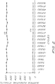
- the life testing cycle of charge --> laser discharge --> erase was repeated at room temperature and normal relative humidity for 100 thousand cycles. The result is illustrated in FIG. 2.
- Example 40 The experiment described in Example 40 was repeated, but using the photoconductor sample described in Comparison Example 1D. The result is illustrated in FIG. 3, which illustrates the build-up of V d with time, thereby reducing ⁇ V (V0 - V d ), which relates to the contrast of the image.
- Comparison Example 1D was repeated, except that the hole transport molecule HT-1 was added to the CGL and adjusted to achieve the final composition described below: x-form metal-free phthalocyanine pigment 5 wt% HT-1 28 wt% B-1 binder 64 wt% Solvent THF Solids (wt%) 8% CGL thickness 10 ⁇ m.
- the photoconductor was exposed to the life cycle test described in Example 40 and the result is illustrated in FIG. 4. As with Comparison Example 40A, the contrast becomes smaller with time.
- the inverse composite dual-layer organic photoconductor using the specific binders and non-chlorinated solvents for processing is expected to find use in electrophotographic printing, particularly in color electrophotographic printing.
- the crosslinking CGL of the improved dual layer of the invention is very useful for liquid toner development, as the crosslinking CGL is strongly inert to solvents.
- the inverted OPC of the present invention is reusable due to stable performance.
Landscapes
- Physics & Mathematics (AREA)
- General Physics & Mathematics (AREA)
- Chemical & Material Sciences (AREA)
- Chemical Kinetics & Catalysis (AREA)
- Spectroscopy & Molecular Physics (AREA)
- Photoreceptors In Electrophotography (AREA)
Applications Claiming Priority (2)
| Application Number | Priority Date | Filing Date | Title |
|---|---|---|---|
| US08/287,437 US5516610A (en) | 1994-08-08 | 1994-08-08 | Reusable inverse composite dual-layer organic photoconductor using specific polymers |
| US287437 | 1994-08-08 |
Publications (3)
| Publication Number | Publication Date |
|---|---|
| EP0697633A2 true EP0697633A2 (de) | 1996-02-21 |
| EP0697633A3 EP0697633A3 (de) | 1997-01-02 |
| EP0697633B1 EP0697633B1 (de) | 1999-09-08 |
Family
ID=23102907
Family Applications (1)
| Application Number | Title | Priority Date | Filing Date |
|---|---|---|---|
| EP95305110A Expired - Lifetime EP0697633B1 (de) | 1994-08-08 | 1995-07-21 | Wiederverwendbarer, inverser, zwei-schichtig zusammengesetzter, organischer Photokonduktor, wobei spezifische Polymere eingesetzt werden die geeignet sind für Diffusionsbeschichtungsverfahren mit nicht chlorierten Lösungsmitteln |
Country Status (4)
| Country | Link |
|---|---|
| US (2) | US5516610A (de) |
| EP (1) | EP0697633B1 (de) |
| JP (1) | JP3641028B2 (de) |
| DE (1) | DE69511970T2 (de) |
Cited By (1)
| Publication number | Priority date | Publication date | Assignee | Title |
|---|---|---|---|---|
| US20120164568A1 (en) * | 2010-12-27 | 2012-06-28 | Xerox Corporation | Charge Transport Layer Containing Symmetric Charge Transport Molecules and High Tg Resins for Imaging Device |
Families Citing this family (12)
| Publication number | Priority date | Publication date | Assignee | Title |
|---|---|---|---|---|
| GB9806066D0 (en) | 1998-03-20 | 1998-05-20 | Cambridge Display Tech Ltd | Multilayer photovoltaic or photoconductive devices |
| US6096470A (en) * | 1999-10-28 | 2000-08-01 | Xerox Corporation | Electrophotographic imaging member overcoat fabrication process |
| US6890693B2 (en) * | 2002-04-12 | 2005-05-10 | Samsung Electronics Co., Ltd. | Organophotoreceptor with an electron transport layer |
| US20030228534A1 (en) * | 2002-05-31 | 2003-12-11 | Jiayi Zhu | Organophotoreceptor with a light stabilizer |
| DE10224979B4 (de) * | 2002-06-05 | 2004-07-15 | Schülke & Mayr GmbH | Verwendung von synergistischen Zubereitungen auf Basis von Gemischen von Glycerinether mit aromatischem Alkohol zur Bekämpfung von Mykobakterien |
| KR100571771B1 (ko) | 2003-12-02 | 2006-04-18 | 삼성전자주식회사 | 신규한 전자수송물질 및 이를 포함하는 전자사진감광체 |
| US20070077478A1 (en) * | 2005-10-03 | 2007-04-05 | The Board Of Management Of Saigon Hi-Tech Park | Electrolyte membrane for fuel cell utilizing nano composite |
| US7920810B2 (en) | 2007-08-15 | 2011-04-05 | Hewlett-Packard Development Company, L.P. | Electrophotography device with electric field applicator |
| US7588873B2 (en) * | 2007-10-23 | 2009-09-15 | Static Control Components, Inc. | Methods and apparatus for providing a liquid coating for an organic photoconductive drum |
| US8765895B2 (en) | 2007-11-08 | 2014-07-01 | Innolene Llc | Crosslinked polyolefins for biomedical applications and method of making same |
| US20100278715A1 (en) * | 2009-04-29 | 2010-11-04 | Th Llc | Systems, Devices, and/or Methods Regarding Specific Precursors or Tube Control Agent for the Synthesis of Carbon Nanofiber and Nanotube |
| US10754266B2 (en) * | 2018-09-21 | 2020-08-25 | Fuji Xerox Co., Ltd. | Electrophotographic photoreceptor, process cartridge, and image forming apparatus |
Citations (9)
| Publication number | Priority date | Publication date | Assignee | Title |
|---|---|---|---|---|
| US4409309A (en) | 1980-07-31 | 1983-10-11 | Fuji Xerox Co., Ltd. | Electrophotographic light-sensitive element |
| US4444862A (en) | 1981-07-28 | 1984-04-24 | Fuji Xerox Co., Ltd. | Electrophotographic photosensitive materials having layer of organic metal compound |
| US4927727A (en) | 1988-08-09 | 1990-05-22 | Eastman Kodak Company | Thermally assisted transfer of small electrostatographic toner particles |
| US4948687A (en) | 1988-01-08 | 1990-08-14 | Fuji Xerox Co., Ltd. | Multi-layered squarylium-based positive charge electrophotographic photoreceptor |
| US4968579A (en) | 1987-07-31 | 1990-11-06 | Mita Industrial Co., Ltd. | Organic laminated photosensitive material of positive charging type and process for preparation thereof |
| US4968578A (en) | 1988-08-09 | 1990-11-06 | Eastman Kodak Company | Method of non-electrostatically transferring toner |
| US5037718A (en) | 1989-12-22 | 1991-08-06 | Eastman Kodak Company | Thermally assisted method of transferring small electrostatographic toner particles to a thermoplastic bearing receiver |
| US5240802A (en) | 1991-12-31 | 1993-08-31 | Eastman Kodak Company | Aggregate photoconductive element and method of making same |
| US5284731A (en) | 1992-05-29 | 1994-02-08 | Eastman Kodak Company | Method of transfer of small electrostatographic toner particles |
Family Cites Families (10)
| Publication number | Priority date | Publication date | Assignee | Title |
|---|---|---|---|---|
| JPS61123848A (ja) * | 1984-11-21 | 1986-06-11 | Canon Inc | 電子写真感光体 |
| US4578334A (en) * | 1984-11-23 | 1986-03-25 | Eastman Kodak Company | Multi-active photoconductive insulating elements and method for their manufacture |
| JPS61179455A (ja) * | 1985-02-05 | 1986-08-12 | Canon Inc | 電子写真感光体の製造方法 |
| US4701396A (en) * | 1986-05-06 | 1987-10-20 | Eastman Kodak Company | Photoconductive phthalocyanine pigments, electrophotographic elements containing them and a method of use |
| JPS63188143A (ja) * | 1987-01-30 | 1988-08-03 | Mita Ind Co Ltd | 複合型電子写真用感光体の製造方法 |
| JPS6432264A (en) * | 1987-07-29 | 1989-02-02 | Mita Industrial Co Ltd | Positively chargeable organic laminated photosensitive body |
| JPH0248669A (ja) * | 1988-08-11 | 1990-02-19 | Fuji Electric Co Ltd | 電子写真用感光体 |
| EP0420580A3 (en) * | 1989-09-27 | 1991-04-24 | Mita Industrial Co., Ltd. | A method for manufacturing an electrophotographic organic photoconductor |
| US5102759A (en) * | 1989-12-01 | 1992-04-07 | Mitsubishi Kasei Corporation | Electrophotographic photoreceptor |
| US5213927A (en) * | 1990-12-17 | 1993-05-25 | Eastman Kodak Company | Inverse multiactive electrophotographic element |
-
1994
- 1994-08-08 US US08/287,437 patent/US5516610A/en not_active Expired - Lifetime
-
1995
- 1995-06-06 US US08/466,001 patent/US5518853A/en not_active Expired - Lifetime
- 1995-07-21 DE DE69511970T patent/DE69511970T2/de not_active Expired - Fee Related
- 1995-07-21 EP EP95305110A patent/EP0697633B1/de not_active Expired - Lifetime
- 1995-08-07 JP JP22113195A patent/JP3641028B2/ja not_active Expired - Fee Related
Patent Citations (9)
| Publication number | Priority date | Publication date | Assignee | Title |
|---|---|---|---|---|
| US4409309A (en) | 1980-07-31 | 1983-10-11 | Fuji Xerox Co., Ltd. | Electrophotographic light-sensitive element |
| US4444862A (en) | 1981-07-28 | 1984-04-24 | Fuji Xerox Co., Ltd. | Electrophotographic photosensitive materials having layer of organic metal compound |
| US4968579A (en) | 1987-07-31 | 1990-11-06 | Mita Industrial Co., Ltd. | Organic laminated photosensitive material of positive charging type and process for preparation thereof |
| US4948687A (en) | 1988-01-08 | 1990-08-14 | Fuji Xerox Co., Ltd. | Multi-layered squarylium-based positive charge electrophotographic photoreceptor |
| US4927727A (en) | 1988-08-09 | 1990-05-22 | Eastman Kodak Company | Thermally assisted transfer of small electrostatographic toner particles |
| US4968578A (en) | 1988-08-09 | 1990-11-06 | Eastman Kodak Company | Method of non-electrostatically transferring toner |
| US5037718A (en) | 1989-12-22 | 1991-08-06 | Eastman Kodak Company | Thermally assisted method of transferring small electrostatographic toner particles to a thermoplastic bearing receiver |
| US5240802A (en) | 1991-12-31 | 1993-08-31 | Eastman Kodak Company | Aggregate photoconductive element and method of making same |
| US5284731A (en) | 1992-05-29 | 1994-02-08 | Eastman Kodak Company | Method of transfer of small electrostatographic toner particles |
Cited By (1)
| Publication number | Priority date | Publication date | Assignee | Title |
|---|---|---|---|---|
| US20120164568A1 (en) * | 2010-12-27 | 2012-06-28 | Xerox Corporation | Charge Transport Layer Containing Symmetric Charge Transport Molecules and High Tg Resins for Imaging Device |
Also Published As
| Publication number | Publication date |
|---|---|
| EP0697633A3 (de) | 1997-01-02 |
| DE69511970T2 (de) | 1999-12-30 |
| US5516610A (en) | 1996-05-14 |
| JP3641028B2 (ja) | 2005-04-20 |
| US5518853A (en) | 1996-05-21 |
| JPH0862866A (ja) | 1996-03-08 |
| EP0697633B1 (de) | 1999-09-08 |
| DE69511970D1 (de) | 1999-10-14 |
Similar Documents
| Publication | Publication Date | Title |
|---|---|---|
| US5804343A (en) | Electrophotographic photoconductor | |
| EP0697633B1 (de) | Wiederverwendbarer, inverser, zwei-schichtig zusammengesetzter, organischer Photokonduktor, wobei spezifische Polymere eingesetzt werden die geeignet sind für Diffusionsbeschichtungsverfahren mit nicht chlorierten Lösungsmitteln | |
| US5208128A (en) | Photoconductive recording material with special outermost layer | |
| EP0780442B1 (de) | Diiminoquinonderivate und ihre Verwendung als Elektronübertragungsmittel | |
| JP3604731B2 (ja) | 有機光導電体用の架橋ポリビニルブチラールバインダー | |
| US5422213A (en) | Multilayer electrophotographic imaging member having cross-linked adhesive layer | |
| GB1588318A (en) | Photoconductive composition | |
| US5952140A (en) | Bipolar charge transport materials useful in electrophotography | |
| US5310613A (en) | High sensitivity visible and infrared photoreceptor | |
| EP0807857B1 (de) | Elektrophotographische Elemente mit bevorzugter Pigment-Teilchengrössenverteilung | |
| JP2008112164A (ja) | 置換ビフェニルジアミンを含有する感光体およびそれを形成する方法 | |
| US20020076632A1 (en) | High mobility charge transporting molecules for a charge transport layer | |
| US5350654A (en) | Photoconductors employing sensitized extrinsic photogenerating pigments | |
| JPH0675389A (ja) | 架橋結合剤系を有する光導電性記録材料 | |
| US5858592A (en) | Terpolymers useful as charge injection barrier materials for photoreceptor | |
| US5698359A (en) | Method of making a high sensitivity visible and infrared photoreceptor | |
| GB2226650A (en) | Electrophotographic imaging member | |
| KR100457529B1 (ko) | 폴리아미노에테르를 이용한 유기 감광체의 오버코트층형성용 조성물 및 이로부터 형성된 오버코트층을 채용한유기 감광체 | |
| US6022656A (en) | Bipolar electrophotographic elements | |
| EP0780365B1 (de) | Diiminoquinonderivate und ihre Verwendung als Elektronübertragungsmittel | |
| EP0811886B1 (de) | Elektrophotographisches, lichtempfindliches Element, sowie eine Prozesskassette und ein elektrophotographisches Gerät die es umfassen | |
| JPH07128872A (ja) | 電子写真感光体とその製造法 | |
| BRPI0605323B1 (pt) | Elemento formador de imagens, método para reduzir o potencial de formação de fantasmas em um elemento formador de imagens e aparelho formador de imagens | |
| US8098925B2 (en) | Photoconductors and processes thereof | |
| JP2874538B2 (ja) | 電子写真用有機感光体 |
Legal Events
| Date | Code | Title | Description |
|---|---|---|---|
| PUAI | Public reference made under article 153(3) epc to a published international application that has entered the european phase |
Free format text: ORIGINAL CODE: 0009012 |
|
| AK | Designated contracting states |
Kind code of ref document: A2 Designated state(s): DE FR GB IT |
|
| RIN1 | Information on inventor provided before grant (corrected) |
Inventor name: HA, TAN Inventor name: GANAPATHIAPPAN, SIVAPACKIA Inventor name: NGUYEN, KHE C. |
|
| PUAL | Search report despatched |
Free format text: ORIGINAL CODE: 0009013 |
|
| AK | Designated contracting states |
Kind code of ref document: A3 Designated state(s): DE FR GB IT |
|
| 17P | Request for examination filed |
Effective date: 19970605 |
|
| 17Q | First examination report despatched |
Effective date: 19980216 |
|
| GRAG | Despatch of communication of intention to grant |
Free format text: ORIGINAL CODE: EPIDOS AGRA |
|
| GRAG | Despatch of communication of intention to grant |
Free format text: ORIGINAL CODE: EPIDOS AGRA |
|
| GRAH | Despatch of communication of intention to grant a patent |
Free format text: ORIGINAL CODE: EPIDOS IGRA |
|
| GRAH | Despatch of communication of intention to grant a patent |
Free format text: ORIGINAL CODE: EPIDOS IGRA |
|
| GRAA | (expected) grant |
Free format text: ORIGINAL CODE: 0009210 |
|
| AK | Designated contracting states |
Kind code of ref document: B1 Designated state(s): DE FR GB IT |
|
| REF | Corresponds to: |
Ref document number: 69511970 Country of ref document: DE Date of ref document: 19991014 |
|
| ET | Fr: translation filed | ||
| ITF | It: translation for a ep patent filed | ||
| PLBE | No opposition filed within time limit |
Free format text: ORIGINAL CODE: 0009261 |
|
| STAA | Information on the status of an ep patent application or granted ep patent |
Free format text: STATUS: NO OPPOSITION FILED WITHIN TIME LIMIT |
|
| 26N | No opposition filed | ||
| REG | Reference to a national code |
Ref country code: GB Ref legal event code: 732E |
|
| REG | Reference to a national code |
Ref country code: FR Ref legal event code: TP |
|
| REG | Reference to a national code |
Ref country code: GB Ref legal event code: IF02 |
|
| PGFP | Annual fee paid to national office [announced via postgrant information from national office to epo] |
Ref country code: DE Payment date: 20070831 Year of fee payment: 13 |
|
| PGFP | Annual fee paid to national office [announced via postgrant information from national office to epo] |
Ref country code: GB Payment date: 20070727 Year of fee payment: 13 |
|
| PGFP | Annual fee paid to national office [announced via postgrant information from national office to epo] |
Ref country code: FR Payment date: 20070717 Year of fee payment: 13 |
|
| GBPC | Gb: european patent ceased through non-payment of renewal fee |
Effective date: 20080721 |
|
| PG25 | Lapsed in a contracting state [announced via postgrant information from national office to epo] |
Ref country code: DE Free format text: LAPSE BECAUSE OF NON-PAYMENT OF DUE FEES Effective date: 20090203 |
|
| REG | Reference to a national code |
Ref country code: FR Ref legal event code: ST Effective date: 20090331 |
|
| PG25 | Lapsed in a contracting state [announced via postgrant information from national office to epo] |
Ref country code: GB Free format text: LAPSE BECAUSE OF NON-PAYMENT OF DUE FEES Effective date: 20080721 |
|
| PG25 | Lapsed in a contracting state [announced via postgrant information from national office to epo] |
Ref country code: FR Free format text: LAPSE BECAUSE OF NON-PAYMENT OF DUE FEES Effective date: 20080731 |
|
| PGFP | Annual fee paid to national office [announced via postgrant information from national office to epo] |
Ref country code: IT Payment date: 20090730 Year of fee payment: 15 |
|
| PG25 | Lapsed in a contracting state [announced via postgrant information from national office to epo] |
Ref country code: IT Free format text: LAPSE BECAUSE OF NON-PAYMENT OF DUE FEES Effective date: 20100721 |