EP0697639B1 - Vorrichtung und Verfahren zur Kollisionsüberwachung - Google Patents
Vorrichtung und Verfahren zur Kollisionsüberwachung Download PDFInfo
- Publication number
- EP0697639B1 EP0697639B1 EP95112793A EP95112793A EP0697639B1 EP 0697639 B1 EP0697639 B1 EP 0697639B1 EP 95112793 A EP95112793 A EP 95112793A EP 95112793 A EP95112793 A EP 95112793A EP 0697639 B1 EP0697639 B1 EP 0697639B1
- Authority
- EP
- European Patent Office
- Prior art keywords
- tool
- processing
- shape data
- machine
- processing material
- Prior art date
- Legal status (The legal status is an assumption and is not a legal conclusion. Google has not performed a legal analysis and makes no representation as to the accuracy of the status listed.)
- Expired - Lifetime
Links
Images





Classifications
-
- G—PHYSICS
- G05—CONTROLLING; REGULATING
- G05B—CONTROL OR REGULATING SYSTEMS IN GENERAL; FUNCTIONAL ELEMENTS OF SUCH SYSTEMS; MONITORING OR TESTING ARRANGEMENTS FOR SUCH SYSTEMS OR ELEMENTS
- G05B19/00—Program-control systems
- G05B19/02—Program-control systems electric
- G05B19/18—Numerical control [NC], i.e. automatically operating machines, in particular machine tools, e.g. in a manufacturing environment, so as to execute positioning, movement or co-ordinated operations by means of program data in numerical form
- G05B19/406—Numerical control [NC], i.e. automatically operating machines, in particular machine tools, e.g. in a manufacturing environment, so as to execute positioning, movement or co-ordinated operations by means of program data in numerical form characterised by monitoring or safety
- G05B19/4068—Verifying part program on screen, by drawing or other means
-
- G—PHYSICS
- G05—CONTROLLING; REGULATING
- G05B—CONTROL OR REGULATING SYSTEMS IN GENERAL; FUNCTIONAL ELEMENTS OF SUCH SYSTEMS; MONITORING OR TESTING ARRANGEMENTS FOR SUCH SYSTEMS OR ELEMENTS
- G05B19/00—Program-control systems
- G05B19/02—Program-control systems electric
- G05B19/18—Numerical control [NC], i.e. automatically operating machines, in particular machine tools, e.g. in a manufacturing environment, so as to execute positioning, movement or co-ordinated operations by means of program data in numerical form
- G05B19/406—Numerical control [NC], i.e. automatically operating machines, in particular machine tools, e.g. in a manufacturing environment, so as to execute positioning, movement or co-ordinated operations by means of program data in numerical form characterised by monitoring or safety
- G05B19/4061—Avoiding collision or forbidden zones
-
- G—PHYSICS
- G05—CONTROLLING; REGULATING
- G05B—CONTROL OR REGULATING SYSTEMS IN GENERAL; FUNCTIONAL ELEMENTS OF SUCH SYSTEMS; MONITORING OR TESTING ARRANGEMENTS FOR SUCH SYSTEMS OR ELEMENTS
- G05B2219/00—Program-control systems
- G05B2219/30—Nc systems
- G05B2219/35—Nc in input of data, input till input file format
- G05B2219/35313—Display, validate tool path for boundary, surface interference
-
- G—PHYSICS
- G05—CONTROLLING; REGULATING
- G05B—CONTROL OR REGULATING SYSTEMS IN GENERAL; FUNCTIONAL ELEMENTS OF SUCH SYSTEMS; MONITORING OR TESTING ARRANGEMENTS FOR SUCH SYSTEMS OR ELEMENTS
- G05B2219/00—Program-control systems
- G05B2219/30—Nc systems
- G05B2219/35—Nc in input of data, input till input file format
- G05B2219/35317—Display tool shape, to select tool for program, or for interference
-
- G—PHYSICS
- G05—CONTROLLING; REGULATING
- G05B—CONTROL OR REGULATING SYSTEMS IN GENERAL; FUNCTIONAL ELEMENTS OF SUCH SYSTEMS; MONITORING OR TESTING ARRANGEMENTS FOR SUCH SYSTEMS OR ELEMENTS
- G05B2219/00—Program-control systems
- G05B2219/30—Nc systems
- G05B2219/36—Nc in input of data, input key till input tape
- G05B2219/36178—Derive finishing allowance, tolerance from shape and work information
-
- G—PHYSICS
- G05—CONTROLLING; REGULATING
- G05B—CONTROL OR REGULATING SYSTEMS IN GENERAL; FUNCTIONAL ELEMENTS OF SUCH SYSTEMS; MONITORING OR TESTING ARRANGEMENTS FOR SUCH SYSTEMS OR ELEMENTS
- G05B2219/00—Program-control systems
- G05B2219/30—Nc systems
- G05B2219/37—Measurements
- G05B2219/37567—3-D vision, stereo vision, with two cameras
Definitions
- the present invention relates to an inspection device and a method for checking interference for machine tools such as a NC machine tool.
- Document EP-A-0 450 113 relates, for example to a digitalizing method including collision examination for crossing geometry data of three-dimensional processing materials.
- the contours of the processing materials as well as the surrounding of the processing materials are scanned by means of a scanning head. From the received scanning signals the geometry data of the processing material is generated and stored in a memory. This process is referred to as "digitalizing".
- the memory stores data are relating to the machine tools and to the movement of the tools during processing. Based on this data collision contemplations are performed, i.e. it is judged on visual basis whether the processing tool collides with the processing material at any stage of the process.
- Document EP-A-0 096 830 discloses a safety system for industrial robots.
- the system contains a photoelectric detection means having a field of vision covering the area of reach of the robot.
- the data concerning the sight obtained through the photoelectric detection means in each of predetermined operation positions is compared with the data concerning the normal or correct sight in the same operation position.
- the movement of the robot to the next operation position is prohibited when a difference of level exceeding a predetermined level is found during the comparison.
- Document EP-A-0 355 454 relates to a method for fabricating sheet metal parts and the like.
- the method and the manufacturing system disclosed therein include computer-aided design terminal and the plurality of manufacturing stations located with respect to a plurality of axes and programmed with a set of manufacturing commands to execute manufacturing and transport operations in accordance with a part definition data records.
- This invention addresses predominantly the execution of manufacturing and transport operations, i.e. relates to transferring workpieces from one work station to another under complete microprocessor-control using known points alloy selected X-axes at a common Y-axes.
- document EP-A-0 395 470 relates to a system for controlling the breackage of processing tools. Therein, processing tools are examined before and after their usage by means of two cameras. Based on the comparison of the obtained images, the control of the processing tools is performed.
- the present invention has been completed turning attention to the above-mentioned problems. It is therefore the object of the present invention to provide an inspection device and an interference check method for machine tools, which are accurate and efficient without depending on the visual inspection of the operator, shorten the time for driving preparation including proving out, and carry out the processing efficiently and safely.
- Fig. 1 is a view illustrating the structure of the system of the inspection device according to the present invention, used for the execution of each check method.
- This inspection device has an arithmetic processor 1 and an image processor 3.
- the arithmetic processor 1 is composed of a micro computer and the like, and includes an interference check section 5, an attached tool check section 7, a processing program check section 9 and a processing propriety check section 11.
- the image-sensing device 17 senses three-dimensionally the image of the processing material W positioned and arranged on the table 21 in a moir manner by the CCD camera 13 under the illumination of the parallel light lattice by the projector 15.
- the CCD camera 19 senses the image of the tool holder 25 and the processing tool 27 attached to the main shaft 23 of the machine tool.
- This image-sensing may be two-dimensional, and the attached portion of the tool holder 25 and the processing tool 27 may be illuminated by an illumination device, though not shown in the drawing, in a back light manner to sense the tool holder 25 and the processing tool 27 as a shadow.
- the image processor 3 inputs the image data output from the CCD camera 13, generates the processing material's shape data showing the three-dimensional shape of the processing material W in the three-dimensional coordinates for every 1 pixel of the sensed image, and outputs the processing material's shape data to the arithmetic processor 1.
- the image processor 3 generates the actual tool's shape data showing the shapes of the tool holder 25 and the processing tool 27 for every 1 pixel of the sensed image by inputting the image data output from the CCD camera 19, and outputs the actual tool's shape data to the arithmetic processor 1.
- the interference check portion 5 inputs the processing material's shape data from the image processor 3 and the processing program of the processing material W from the programming device 29, respectively, and inputs also the machine's shape data defining the three-dimensional shape of the machine side including the main shaft head provided with the processing tool and the tool holder attached thereto, and determines by the arithmetic processing whether the coordinate position of the processing material W given by the processing material's shape data is in the space to be occupied by the machine given by the machine shape data or not at the relative movement position between the main shaft head and the work table of the machine tool by the feed command described in the processing program, and when the coordinate position of the processing material is in the space to be occupied by the machine, it is determined that the processing material and the machine interfere with each other and outputs the interference check result.
- the attached tool check section 7 inputs the actual tool's shape data from the image processor 3, and inputs the tool's shape data defining the shapes of the processing tool and the tool holder, comparatively verifies the actual tool's shape data and the tool's shape data to determine whether the actual tool's shape data and the tool's shape data are different or not, and when they are different, determines that it is the attachment error of the processing tool and the tool holder and outputs the attached tool check result.
- This comparison of the shape data in the attached tool check section 7 may be the three-dimensional data or the two-dimensional data, and in the case of the comparison by the three-dimensional shape data, the tool's shape data may invoke the machine's shape data in the interference check described above, and in the case of the comparison by the two-dimensional shape data, the tool's shape data may be the one in which the machine's shape data in the above-mentioned interference check is converted to the two-dimensional shape data.
- the processing program check section 9 inputs the processing material's shape data and the product's shape data defining the three-dimensional shape of the processed product after having completed the processing from the image processor 3 and the CAD device 30, respectively, determines whether the difference between the processing material's shape data and the product's shape data at the same coordinate position is larger than the standard entering margin or not by means of the comparative arithmetic processing, and when said difference is larger than the standard entering margin, outputs a command to change the processing program.
- the processing propriety check section 11 inputs the processing material's shape data and the product's shape data defining the three-dimensional shape of the processed product after having completed the processing from the image processor 3 and the CAD device 30, respectively, determines whether the difference between the processing material's shape data and the product's shape data at the same coordinate position is larger than the prescribed value or not by means of the comparative arithmetic processing, and when said difference is larger than the prescribed value, determines that it is a preparation error of the processing program or it is an abnormal shape of the processing material to output the processing propriety result.
- FIG. 2 is a view illustrating the structure of the system according to the present invention when each check method is executed on the machine tool by an on-machine method.
- a gate-shaped machining center 31 has a bed 33, a work table 35 arranged on the bed 33 and movable in the direction of X-axis, a gate-shaped fixed frame 37 fixedly arranged striding over the bed 33 in the direction of Y-axis, a cross beam 39 provided movably in the vertical direction (in a direction of Z-axis) on the gate-shaped fixed frame 37, a saddle 41 provided movably in the direction of Y-axis on the cross beam 39, and a ram 43 provided movably in the direction of Z-axis on the saddle 41, and when the processing material W positioned and arranged on the work table 35 is three-dimensionally measured, a three-dimensional image-sensing head 45 comprising a CCD camera and a projector is attached downward at the lower end of the ram 43, instead of the processing head.
- the three-dimensional image-sensing head 45 receives the projector-driving command from the image processor 47, senses the image of the processing material W positioned and arranged on the work table 35 three-dimensionally in a moir manner, and outputs the image data of the processing material W to the three-dimensional image processor 47.
- a CCD camera 49 for the image-sensing of the attached tool which senses the images of the tool holder and the processing tool attached to the main shaft of the processing head attached to the ram 43 at the time of processing.
- the image processor 47 inputs the image data from the CCD camera of the three-dimensional image-sensing head 45 and the CCD camera 49 for the image-sensing of the attached tool, generates the processing material's shape data showing the three-dimensional shape of the processing material W in the three-dimensional coordinates per one pixel of the image-sensed image, and outputs the processing material's shape data to the CAD/CAM device 51 in a computer system.
- the image processor 47 inputs the image data from the CCD camera 49 for the image-sensing of the attached tool, generates the actual tool's shape data showing the shape of the tool holder and the processing tool attached to the main shaft per one pixel of the image-sensed image, and outputs the actual tool's shape data to the CAD/CAM device 51.
- the CAD/CAM device 51 generates a product's shape data defining the three-dimensional shape of the processed product after having completed the processing by means of the CAD function, and generates the processing program of the NC from the product's shape data by means of the CAM function, to output the processing program to the NC device 52 of the gate-shaped machining center 31.
- the CAD/CAM device 51 outputs a measuring program to the NC device 52, and the NC device 52 outputs a command of each axis X, Y, and Z to the gate-shaped machining center 31 according to the measuring/image-sensing program at the time of measuring the three-dimensional shape of the processing material W by means of the three-dimensional image-sensing head 45, or at the time of image-sensing the attached tool by means of the CCD camera 49 for the image-sensing of the attached tool.
- the relative position between the three-dimensional image-sensing head 45 and the processing material W is set to the position prescribed preliminarily.
- the CAD/CAM device 51 inputs the processing material's shape data from the image processor 47 as well as the machine's shape data, and executes the check program, thereby performs the interference check, the attached tool check, the processing program check, and the processing propriety check.
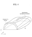
- Fig. 4 shows one embodiment of the processing material's shape and the product's shape.
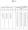
- Fig. 5(a) shows the example of data of the processing material's shape data [Xw(n), Yw(n), Zw(n)].
- Fig. 5(b) shows the example of data of the product's shape data [Xp(n), Yp(n), Zp(n)].
- the monitor screen of the CAD/ CAM device 49 becomes the editing screen of the processing program, and the processing program on the line where the change of the processing number is required is displayed on the screen.
- the operator executes to change the processing number.
- the number of change of the processing number is set automatically by the internal processing with the CAD/CAM device, and it may be such that the operator confirms only Yes or No regarding the change of the processing number.
- the interference check will be started.
- the shape data of the main shaft head and the shape data of the tool holder are read in as machine informations, and the shape data by the diameter and the shaft length of the tool is read in as the tool information (Step 110).
- These data are preliminarily input to the CAD/CAM device 49 for every main shaft head and every tool, and by combining these data, the machine's shape data defining the three-dimensional shape of the machine including the main shaft head provided with a processing tool and a tool holder attached thereto can be obtained.
- This interference check is to determine whether the main shaft head including the processing tool and the tool holder at the relative movement position between the main shaft head and the work table 35 which is defined by the feed command in each block of the NC program collides with the processing material W on the work table 35, and calculate the coordinate value in the space to be occupied by the machine from the relative movement position data between the main shaft head and the work table 35 and the machine's shape data, determine whether the coordinate position of the processing material W is in the space to be occupied by the machine by comparison of this coordinate value with the processing material's shape data [Xw(n), Yw(n), Zw(n)], and when the coordinate position of the processing material W is in the space to be occupied by the machine, determine that the processing material W and the machine interfere with each other. If they interfere with each other, a message representing that they interfere is output on the monitor (Step 160), and complete the check routine.
- Step 170 the attached tool check is conducted (Step 170).
- This attached tool check is to comparatively verify the actual tool's shape data and the tool's shape data and to determine whether the actual tool's shape data and the tool's shape data are different or not, and when they are different, determine that it is an attachement error of the processing tool and the tool holder, and output a message representing that it is a tool attachment error on the monitor (Step 180).
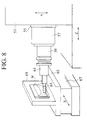
- a main shaft 59 is attached to a ram 55 of a saddle 53 by an attachment 57, and to the tip of the main shaft 59, a processing tool 63 is exchangeably attached by a tool holder 61, and the processing tool 63 is movable in the directions of Y-axis and Z-axis.
- the work table 65 is movable in the direction of X-axis on the bed 67, and a processing material W is attached on the table surface by a jig 69.
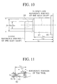
- the machine coordinate in the center of the work table 65 to be the machine's reference coordinate value (Xm 0 , Ym 0 , Zm 0 ), and as shown in Fig. 10, assume the tip face of the main shaft 57 to be the Z-axis reference position of the main shaft, the rotational center position of the main shaft 57 to be the X-axis reference position of the main shaft, and the Y-axis reference position of the main shaft to be Ys 0 , and assume the dimensions of respective portions to be Ls 1 , Ls 2 , Ls 3 , Ds 1 , Ds 2 , Ds 3 . Moreover, as shown in Fig.
- the machine's reference coordinate value (Xm 0 , Ym 0 , Zm 0 ) is the origin of the position to be attached of the material to be processed W in the work table 65, and it shows the deviation with the coordinate value of the machine's origin.
- the coordinate value (Xwm(n), Ywm(n), Zwm(n)) in the machine coordinate systems of the processing material W can be determined by the following equation.
- This coordinate value (Xwm(n), Ywm(n), Zwm(n)) is a global coordinate value with respect to the coordinate value of the machine's origin.
- L 1 Lt 1
- L 2 Lt 2
- L 3 Lt 3
- L 4 - Ls 1
- L 5 - Ls 1 + Ls 2
- L 6 - Ls 1 + Ls 3 .
- R 1 Dt1/2
- R 2 Dt2/2
- R 3 Dt3/2
- R 4 Ds1/2
- R 5 Ds2/2
- R 6 Ds3/2
- a numerical formula showing a surface S made by a surface of the processing material W is formed from the coordinate position Pn (Xwm(n), Ywm(n), Zwm(n)) in the machine coordinate systems of the processing material W, and at the coordinate position (Xtm, Ytm, Ztm), determination whether the cylindrical space C(k) determined by the radius R(k) and the shaft length L(k) and the surface S cross over or not is carried out by the numerical calculation.
- the measurement of the three-dimensional shape of the processing material may be carried out other than on the work table of the machine tool, by using a three-dimensional shape-measuring device separate from the machine tool having a holding means of the three-dimensional measurement detector and a table which can position and arrange the processing material at the three-dimensional shape-measuring position by the three-dimensional measurement detector, and in which the table is constituted by the XY stage according to need.
- the measurement of the three-dimensional shape of the processing material may be carried out by a three-dimensional shape-measuring device using a contact needle, other than using the image-sensing data by the three-dimensional image-sensing device using a CCD camera.
- the interference check to find a preparation error of the processing program, to find the necessity to change the processing program, to find the abnormal shape of the processing material can be carried out automatically, exactly and efficiently without depending on the visual inspection of the operator by the comparison of the processing material's shape data, the machine's shape data and the product's shape data obtained by measuring the three-dimensional shape of the processing material by the three-dimensional measurement detector, and also it is carried out automatically and exactly without depending on the visual inspection of the operator by the comparative verification of the image-sensed data of the processing tool and the tool holder attached to the machine tool (actual tool's shape data) with the tool's shape data to find the attachment error of the tool, and the time for driving preparation including proving out can be shortened and the driving of the machine tools can be carried out efficiently and safely.
- the machine tool When the measurement of the three-dimensional shape of the processing material by the three-dimensional measurement detector is carried out by using a three-dimensional shape-measuring device separate from the machine tool, the machine tool is not occupied for measuring the three-dimensional shape of the processing material and the rate of operation of the machine tool is not decreased. Furthermore, when a plurality of processing materials are sequentially processed, during the processing of one processing material, measurement of the three-dimensional shape of the next processing material can be carried out, thereby the time required for the entire processing can be reduced.
Landscapes
- Engineering & Computer Science (AREA)
- Human Computer Interaction (AREA)
- Manufacturing & Machinery (AREA)
- Physics & Mathematics (AREA)
- General Physics & Mathematics (AREA)
- Automation & Control Theory (AREA)
- Numerical Control (AREA)
- Safety Devices In Control Systems (AREA)
Claims (5)
- Prüfungsvorrichtung, die folgendes aufweist:gekennzeichnet durcheinen dreidimensionalen Meßdetektor (13, 15) zur Bilderfassung eines Verarbeitungsmaterials (W);eine dreidimensionale Bilderfassungsvorrichtung (19) zur Bilderfassung eines Werkzeughalters (25) und eines Verarbeitungswerkzeugs (27), die an einer Hauptwelle (23) angebracht sind;eine Bildprozessoreinrichtung (3), die mit dem dreidimensionalen Meßdetektor (13, 15) und der dreidimensionalen Bilderfassungsvorrichtung (19) verbunden ist, zum Erzeugen der Daten, die für eine Interferenzprüfung verwendet werden, aus den erfaßten Bildern für Formdaten des Verarbeitungsmaterials und Formdaten eines tatsächlichen Werkzeugs;eine Programmiervorrichtung (29) zum Vorsehen eines Verarbeitungsprogramms,
eine Arithmetik-Prozessoreinrichtung (1), die mit der Bildprozessoreinrichtung (3) und der Programmiervorrichtung (29) verbunden ist, wobei die Arithmetik-Prozessoreinrichtung (1) folgendes aufweist:einen Interferenzprüfungsabschnitt (5) zum Ausgeben eines Ergebnisses der Interferenzprüfung basierend auf den erzeugten Formdaten des Verarbeitungsmaterials und auf Maschinenformdaten, die die dreidimensionale Form der Maschinenseite einschließlich der Hauptwelle (23) definieren, die mit dem Verarbeitungswerkzeug (27) und dem Werkzeughalter (25) versehen ist;einen Abschnitt (7) zur Prüfung eines angebrachten Werkzeugs zum Bestimmen eines Anbringungsfehlers basierend auf dem Vergleich der erzeugten Formdaten des aktuellen Werkzeugs und der Formdaten des Werkzeugs, die die Formen des Verarbeitungswerkzeugs (27) und des Werkzeughalters (25) definieren;einen Verarbeitungsprogramm-Prüfabschnitt (9) zum Beurteilen des Verarbeitungsprogramms basierend auf den erzeugten Formdaten des Verarbeitungsmaterials und der Formdaten eines Produkts, die die dreidimensionale Form des Verarbeitungsmaterials (W) definieren, nachdem die Verarbeitung beendet worden ist;einen Verarbeitungseigenschaften-Prüfabschnitt (11) zum Ausgeben eines Verarbeitungseigenschaftenergebnisses basierend auf den erzeugten Formdaten des Verarbeitungsmaterials und den Formdaten des Produkts. - Prüfungsvorrichtung nach Anspruch 1,
dadurch gekennzeichnet, daßder dreidimensionale Meßdetektor (13, 15) eine Meßvorrichtung für eine dreidimensionale Form ist, die vom Maschinenwerkzeug bzw. Bearbeitungswerkzeug getrennt ist und die eine Halteeinrichtung für den dreidimensionalen Meßdetektor (13, 15) aufweist, undein Arbeitstisch (21; 35) das Verarbeitungsmaterial (W) bei einer Meßposition mit dreidimensionaler Form positioniert und anordnet. - Verfahren zum Prüfen einer Interferenz, das die folgenden Schritte aufweist:Messen der dreidimensionalen Form eines Verarbeitungsmaterials (W) mittels eines dreidimensionalen Meßdetektors (13, 15);Erzeugen von Formdaten des Verarbeitungsmaterials basierend auf dem erfaßten Bild des Verarbeitungsmaterials (W);Erhalten von Formdaten einer Maschine, die die dreidimensionale Form der Maschinenseite definieren, einschließlich eines Hauptwellenkopfes (33), der mit einem Verarbeitungswerkzeug (27) und einem Werkzeughalter (25) versehen ist, die daran angebracht sind;Bestimmen, ob die Koordinatenposition des durch die Formdaten des Verarbeitungsmaterials gegebenen Verarbeitungsmaterials (W) in dem Raum ist oder nicht, der durch die Maschine besetzt ist, die durch die Formdaten der Maschine gegeben ist, bei der relativen Bewegungsposition zwischen dem Hauptwellenkopf (23) des Maschinenwerkzeugs und einem Arbeitstisch (21; 35), durch eine arithmetische Verarbeitung unter Verwendung einer Arithmetik-Verarbeitungseinrichtung (1);Ausgeben eines Interferenzprüfergebnisses bei einer Interferenzposition, wenn die Koordinatenposition des Verarbeitungsmaterials (W) in dem Raum ist, der durch die Maschine besetzt ist.
- Verfahren zum Prüfen einer Interferenz nach Anspruch 3, das weiterhin die folgenden Schritte aufweist:eine Bilderfassung des Verarbeitungswerkzeugs (27) und des Werkzeughalters (25);Erzeugen von Formdaten eines aktuellen Werkzeugs basierend auf den erfaßten Bildern des Verarbeitungswerkzeugs (27) und des Werkzeughalters (25);Erhalten von Formdaten des Werkzeugs, die die Form des Verarbeitungswerkzeugs (27) und des Werkzeughalters (25) definieren;Ausführen einer vergleichenden Verifizierung zwischen den Formdaten des aktuellen Werkzeugs und den Formdaten des Werkzeugs unter Verwendung der Arithmetik-Verarbeitungseinrichtung (1); undBestimmen eines Anbringungsfehlers des Verarbeitungswerkzeugs (27) und des Werkzeughalters (25), wenn die aktuellen Formdaten des Werkzeugs und die Formdaten des Werkzeugs unterschiedlich sind.
- Verfahren zum Prüfen einer Interferenz nach Anspruch 3, das weiterhin die folgenden Schritte aufweist:Messen der dreidimensionalen Form des Verarbeitungsmaterials (W) auf der Koordinatenachse des Maschinenwerkzeugs durch Anbringen des dreidimensionalen Meßdetektors (13, 15) anstelle eines Verarbeitungswerkzeugs am Hauptwellenkopf (23) des Bearbeitungswerkzeugs, undrelatives Verschieben des Arbeitstischs (21) des Maschinenwerkzeugs, auf welchem das Verarbeitungsmaterial (W) angeordnet ist, und des Hauptwellenkopfes (23) in der Koordinatenrichtung des Maschinenwerkzeugs.
Applications Claiming Priority (3)
| Application Number | Priority Date | Filing Date | Title |
|---|---|---|---|
| JP6191525A JPH0852638A (ja) | 1994-08-15 | 1994-08-15 | 干渉チェック方法および加工プログラムチェック方法および加工適否チェック方法 |
| JP19152594 | 1994-08-15 | ||
| JP191525/94 | 1994-08-15 |
Publications (2)
| Publication Number | Publication Date |
|---|---|
| EP0697639A1 EP0697639A1 (de) | 1996-02-21 |
| EP0697639B1 true EP0697639B1 (de) | 2001-10-31 |
Family
ID=16276118
Family Applications (1)
| Application Number | Title | Priority Date | Filing Date |
|---|---|---|---|
| EP95112793A Expired - Lifetime EP0697639B1 (de) | 1994-08-15 | 1995-08-14 | Vorrichtung und Verfahren zur Kollisionsüberwachung |
Country Status (4)
| Country | Link |
|---|---|
| US (1) | US5751584A (de) |
| EP (1) | EP0697639B1 (de) |
| JP (1) | JPH0852638A (de) |
| DE (1) | DE69523520T2 (de) |
Families Citing this family (24)
| Publication number | Priority date | Publication date | Assignee | Title |
|---|---|---|---|---|
| DE19846426A1 (de) * | 1998-10-08 | 2000-04-13 | Open Mind Software Technologie | Verfahren zum Steuern der Arbeitsbewegung eines Werkzeugs zur materialabtragenden Bearbeitung eines Materialblocks |
| DE10044306A1 (de) * | 2000-09-07 | 2002-04-04 | Juergen Roeders | Werkzeugmaschine |
| US7062351B2 (en) * | 2003-09-25 | 2006-06-13 | The Boeing Company | Clamp avoidance cutter path regeneration |
| JP2005125339A (ja) * | 2003-10-21 | 2005-05-19 | Hitachi Via Mechanics Ltd | レーザ加工装置 |
| WO2008025577A1 (de) * | 2006-05-30 | 2008-03-06 | Siemens Aktiengesellschaft | Verfahren zur einrichtung zur kollisionsüberwachung eines maschinenelements mit einem gegenstand bei einer werkzeugmaschine, produktionsmaschine und/oder bei einer als roboter ausgebildeten maschine |
| JP4221016B2 (ja) * | 2006-07-25 | 2009-02-12 | ファナック株式会社 | 干渉チェックを行う数値制御装置 |
| JP4865490B2 (ja) * | 2006-10-06 | 2012-02-01 | 株式会社ツガミ | 旋盤、旋盤制御用コンピュータプログラム及び旋盤における加工方法 |
| JP5173510B2 (ja) * | 2008-03-24 | 2013-04-03 | オークマ株式会社 | 加工シミュレーション装置 |
| KR101575780B1 (ko) * | 2008-07-10 | 2015-12-08 | 시티즌 마쉬나리 가부시키가이샤 | 간섭 체크 장치 및 간섭 체크 방법 및 간섭 체크 장치를 갖춘 공작기계 |
| EP2561958B1 (de) * | 2010-04-23 | 2014-08-20 | Mitsubishi Heavy Industries, Ltd. | Vorrichtung zum messen der form eines werkstücks in einer werkzeugmaschine |
| WO2013187203A1 (ja) * | 2012-06-12 | 2013-12-19 | 株式会社島精機製作所 | 3次元計測装置と3次元計測方法 |
| CN102975082A (zh) * | 2012-10-29 | 2013-03-20 | 上海工程技术大学 | 基于图像信息辅助的多轴加工无干涉刀路检测方法 |
| WO2014128890A1 (ja) * | 2013-02-21 | 2014-08-28 | 三菱電機株式会社 | 干渉チェック装置および数値制御装置 |
| JP6200456B2 (ja) * | 2015-06-29 | 2017-09-20 | ファナック株式会社 | 工作機械とロボット間の干渉チェックシステム |
| JP6412185B2 (ja) | 2017-03-02 | 2018-10-24 | ファナック株式会社 | 工作機械システム |
| US20210291309A1 (en) * | 2018-07-10 | 2021-09-23 | Makino Milling Machine Co., Ltd. | Machine tool system, and tool determining method |
| DE102018123363B4 (de) * | 2018-09-24 | 2021-01-07 | Bystronic Laser Ag | Verfahren zur Kollisionsvermeidung und Laserbearbeitungsmaschine |
| DE102018125620A1 (de) * | 2018-10-16 | 2020-04-16 | Schuler Pressen Gmbh | Verfahren und Vorrichtung zum Schneiden einer Blechplatine aus einem kontinuierlich geförderten Blechband |
| JP7510244B2 (ja) * | 2018-11-26 | 2024-07-03 | 株式会社Subaru | 部品加工装置 |
| JP6758441B2 (ja) * | 2019-02-18 | 2020-09-23 | 株式会社アマダ | レーザ加工機、レーザ加工方法、及び加工プログラム作成装置 |
| DE102021116899A1 (de) * | 2021-06-30 | 2023-01-05 | Messer Cutting Systems Gmbh | Verfahren zur thermischen Bearbeitung eines Werkstücks mit einer thermischen Bearbeitungsmaschine |
| JP7802558B2 (ja) * | 2022-02-03 | 2026-01-20 | 株式会社小松製作所 | 加工機械、加工機械の制御装置および加工機械の制御方法 |
| CN115722978A (zh) * | 2022-11-15 | 2023-03-03 | 西安秦玄汉信息科技有限公司 | 一种基于逆运动学的旁轴在线校正方法 |
| WO2024166291A1 (ja) * | 2023-02-09 | 2024-08-15 | 株式会社ニコン | 情報処理方法、情報処理装置、加工装置及び加工方法 |
Family Cites Families (33)
| Publication number | Priority date | Publication date | Assignee | Title |
|---|---|---|---|---|
| US3829750A (en) * | 1971-02-12 | 1974-08-13 | Bendix Corp | Self-adaptive process control |
| US4031368A (en) * | 1972-04-17 | 1977-06-21 | Verkstadsteknik Ab | Adaptive control of cutting machining operations |
| US4146924A (en) * | 1975-09-22 | 1979-03-27 | Board Of Regents For Education Of The State Of Rhode Island | System for visually determining position in space and/or orientation in space and apparatus employing same |
| GB1573142A (en) * | 1976-01-23 | 1980-08-13 | Hitachi Ltd | Apparatus and method for providing information relating to shape and/or position of an object |
| US4236794A (en) * | 1979-03-05 | 1980-12-02 | Gordon Gary B | Self-focusing camera apparatus and method |
| US4187051A (en) * | 1978-05-26 | 1980-02-05 | Jerry Kirsch | Rotary video article centering, orienting and transfer device for computerized electronic operating systems |
| JPS558102A (en) * | 1978-07-03 | 1980-01-21 | Olympus Optical Co Ltd | Picture signal process circuit |
| GB2054199B (en) * | 1979-06-14 | 1983-10-05 | Daihatsu Motor Co Ltd | Numerically controlled machine tool |
| JPS58163001A (ja) * | 1982-03-23 | 1983-09-27 | Toyoda Mach Works Ltd | 干渉チエツク機能を備えた数値制御装置 |
| JPS58217294A (ja) * | 1982-06-07 | 1983-12-17 | 株式会社日立製作所 | 産業用ロボツトの安全装置 |
| US4509126A (en) * | 1982-06-09 | 1985-04-02 | Amca International Corporation | Adaptive control for machine tools |
| JPS59216208A (ja) * | 1983-05-23 | 1984-12-06 | Mitsubishi Electric Corp | 数値制御装置 |
| US4618938A (en) * | 1984-02-22 | 1986-10-21 | Kla Instruments Corporation | Method and apparatus for automatic wafer inspection |
| US4613269A (en) * | 1984-02-28 | 1986-09-23 | Object Recognition Systems, Inc. | Robotic acquisition of objects by means including histogram techniques |
| US4659220A (en) * | 1984-10-22 | 1987-04-21 | International Business Machines Corporation | Optical inspection system for semiconductor wafers |
| GB2173300B (en) * | 1985-04-06 | 1989-06-28 | Schaudt Maschinenbau Gmbh | Apparatus for optically monitoring the surface finish of ground workpieces |
| US4998206A (en) * | 1988-07-29 | 1991-03-05 | The Boeing Company | Automated method and apparatus for fabricating sheet metal parts and the like using multiple manufacturing stations |
| US4667113A (en) * | 1985-08-09 | 1987-05-19 | Hitachi Seiko Ltd. | Tool failure detection apparatus |
| US4878736A (en) * | 1986-10-17 | 1989-11-07 | Global Holonetics Corporation | Control means and method for optical inspection system |
| US4916640A (en) * | 1987-06-03 | 1990-04-10 | Allen-Bradley Company, Inc. | Video image processing system |
| US4869813A (en) * | 1987-07-02 | 1989-09-26 | Northrop Corporation | Drill inspection and sorting method and apparatus |
| GB8720331D0 (en) * | 1987-08-28 | 1987-10-07 | Caplin Cybernetics Corp | Control system |
| FR2640902B1 (de) * | 1988-12-23 | 1992-02-07 | Commissariat Energie Atomique | |
| FR2645782B1 (fr) * | 1989-04-14 | 1995-01-27 | Aerospatiale | Systeme de controle de bris d'outil sur centre d'usinage |
| US5062052B1 (en) * | 1989-06-20 | 1997-11-18 | Cincinnati Milacron Inc | Logic controlled plastic molding machine with programmable operator interface |
| US5097587A (en) * | 1989-09-04 | 1992-03-24 | Brother Kogyo Kabushiki Kaisha | Numerically controlled machine tool with automatic tool exchange device and indexing device |
| DE59009295D1 (de) * | 1990-04-02 | 1995-07-27 | Heidenhain Gmbh Dr Johannes | Digitalisier-Verfahren mit Kollisionsprüfung. |
| US5095204A (en) * | 1990-08-30 | 1992-03-10 | Ball Corporation | Machine vision inspection system and method for transparent containers |
| DE4134750C2 (de) * | 1990-10-22 | 1997-01-23 | Toshiba Machine Co Ltd | Verfahren und Anordnung zur Erzeugung eines NC-Arbeitsprogramms für eine numerische Werkzeugmaschinensteuerung einer Werkzeugmaschine |
| US5255199A (en) * | 1990-12-14 | 1993-10-19 | Martin Marietta Energy Systems, Inc. | Cutting tool form compensaton system and method |
| US5387061A (en) * | 1990-12-14 | 1995-02-07 | The United States Of America As Represented By The United States Department Of Energy | Parameter monitoring compensation system and method |
| US5289282A (en) * | 1991-05-28 | 1994-02-22 | Matsushita Electric Industrial Co., Ltd. | Video signal gradation corrector |
| EP0648358A4 (de) * | 1992-05-18 | 1995-12-13 | Sensor Adaptive Mach | Verfahren und gerät zur steuerung von stangen und anderen werkzeugmaschinen. |
-
1994
- 1994-08-15 JP JP6191525A patent/JPH0852638A/ja active Pending
-
1995
- 1995-08-14 US US08/514,666 patent/US5751584A/en not_active Expired - Fee Related
- 1995-08-14 EP EP95112793A patent/EP0697639B1/de not_active Expired - Lifetime
- 1995-08-14 DE DE69523520T patent/DE69523520T2/de not_active Expired - Fee Related
Also Published As
| Publication number | Publication date |
|---|---|
| US5751584A (en) | 1998-05-12 |
| JPH0852638A (ja) | 1996-02-27 |
| EP0697639A1 (de) | 1996-02-21 |
| DE69523520D1 (de) | 2001-12-06 |
| DE69523520T2 (de) | 2002-05-08 |
Similar Documents
| Publication | Publication Date | Title |
|---|---|---|
| EP0697639B1 (de) | Vorrichtung und Verfahren zur Kollisionsüberwachung | |
| US4513366A (en) | Menu programmed machine tool numerical controller with an interference checking function | |
| EP1527850B1 (de) | Simulationsvorrichtung | |
| US4918627A (en) | Computer integrated gaging system | |
| Lee et al. | Automated inspection planning of free-form shape parts by laser scanning | |
| US7177459B1 (en) | Robot system having image processing function | |
| US7333879B2 (en) | Offline programming device | |
| US7403648B2 (en) | Apparatus for generating three-dimensional model data | |
| US20130282328A1 (en) | Error measurment device and error measurement method | |
| US20050159842A1 (en) | Measuring system | |
| JP4180469B2 (ja) | 工作機械の加工適否チェック方法 | |
| JP2010058264A (ja) | 加工状態確認方法及び加工状態確認装置 | |
| US20020169586A1 (en) | Automated CAD guided sensor planning process | |
| US20240082976A1 (en) | Apparatus for measuring a tool or a complete tool, tool, processing center and method for compiling a digital image of a tool or a complete tool | |
| JP2019117477A (ja) | リンク情報生成装置、リンク情報生成方法及びリンク情報生成プログラム | |
| EP1400881A2 (de) | Verfahren und Vorrichtung zur unterstützenden Messung von einem zu messenden Objekt | |
| JP3517529B2 (ja) | 画像入力型ロボットシステム | |
| JP2666512B2 (ja) | 機械座標系補正装置 | |
| JP2002268718A (ja) | 加工パス作成方法、3次元cam装置及びコンピュータにより読み取り可能な記憶媒体 | |
| GB2230363A (en) | Tolerance analysis in cad system | |
| WO2020065854A1 (ja) | ワーク位置検出方法及び工作機械 | |
| US5278479A (en) | Tool path drawing method | |
| CN121223595A (zh) | 高精度集成式对刀检测系统及其控制方法 | |
| Chalus et al. | 3D robotic welding with a laser profile scanner | |
| Ali | Development of a STEP-NC-compliant feature-based inspection framework for prismatic parts |
Legal Events
| Date | Code | Title | Description |
|---|---|---|---|
| PUAI | Public reference made under article 153(3) epc to a published international application that has entered the european phase |
Free format text: ORIGINAL CODE: 0009012 |
|
| 17P | Request for examination filed |
Effective date: 19950814 |
|
| AK | Designated contracting states |
Kind code of ref document: A1 Designated state(s): DE FR GB |
|
| 17Q | First examination report despatched |
Effective date: 19980416 |
|
| GRAG | Despatch of communication of intention to grant |
Free format text: ORIGINAL CODE: EPIDOS AGRA |
|
| RTI1 | Title (correction) |
Free format text: INSPECTION DEVICE AND METHOD FOR CHECKING INTERFERENCE |
|
| RTI1 | Title (correction) |
Free format text: INSPECTION DEVICE AND METHOD FOR CHECKING INTERFERENCE |
|
| GRAG | Despatch of communication of intention to grant |
Free format text: ORIGINAL CODE: EPIDOS AGRA |
|
| GRAH | Despatch of communication of intention to grant a patent |
Free format text: ORIGINAL CODE: EPIDOS IGRA |
|
| GRAH | Despatch of communication of intention to grant a patent |
Free format text: ORIGINAL CODE: EPIDOS IGRA |
|
| GRAA | (expected) grant |
Free format text: ORIGINAL CODE: 0009210 |
|
| AK | Designated contracting states |
Kind code of ref document: B1 Designated state(s): DE FR GB |
|
| REF | Corresponds to: |
Ref document number: 69523520 Country of ref document: DE Date of ref document: 20011206 |
|
| REG | Reference to a national code |
Ref country code: GB Ref legal event code: IF02 |
|
| ET | Fr: translation filed | ||
| PLBE | No opposition filed within time limit |
Free format text: ORIGINAL CODE: 0009261 |
|
| STAA | Information on the status of an ep patent application or granted ep patent |
Free format text: STATUS: NO OPPOSITION FILED WITHIN TIME LIMIT |
|
| 26N | No opposition filed | ||
| PGFP | Annual fee paid to national office [announced via postgrant information from national office to epo] |
Ref country code: DE Payment date: 20080821 Year of fee payment: 14 |
|
| PGFP | Annual fee paid to national office [announced via postgrant information from national office to epo] |
Ref country code: FR Payment date: 20080731 Year of fee payment: 14 |
|
| PGFP | Annual fee paid to national office [announced via postgrant information from national office to epo] |
Ref country code: GB Payment date: 20080811 Year of fee payment: 14 |
|
| GBPC | Gb: european patent ceased through non-payment of renewal fee |
Effective date: 20090814 |
|
| REG | Reference to a national code |
Ref country code: FR Ref legal event code: ST Effective date: 20100430 |
|
| PG25 | Lapsed in a contracting state [announced via postgrant information from national office to epo] |
Ref country code: FR Free format text: LAPSE BECAUSE OF NON-PAYMENT OF DUE FEES Effective date: 20090831 Ref country code: DE Free format text: LAPSE BECAUSE OF NON-PAYMENT OF DUE FEES Effective date: 20100302 |
|
| PG25 | Lapsed in a contracting state [announced via postgrant information from national office to epo] |
Ref country code: GB Free format text: LAPSE BECAUSE OF NON-PAYMENT OF DUE FEES Effective date: 20090814 |