EP0697657A1 - Verfahren für die Ablauffolgeplanung von aufeinanderfolgenden Aufgaben mit Zeitzwangsbedienungen - Google Patents
Verfahren für die Ablauffolgeplanung von aufeinanderfolgenden Aufgaben mit Zeitzwangsbedienungen Download PDFInfo
- Publication number
- EP0697657A1 EP0697657A1 EP95401867A EP95401867A EP0697657A1 EP 0697657 A1 EP0697657 A1 EP 0697657A1 EP 95401867 A EP95401867 A EP 95401867A EP 95401867 A EP95401867 A EP 95401867A EP 0697657 A1 EP0697657 A1 EP 0697657A1
- Authority
- EP
- European Patent Office
- Prior art keywords
- task
- tasks
- max
- suite
- constraints
- Prior art date
- Legal status (The legal status is an assumption and is not a legal conclusion. Google has not performed a legal analysis and makes no representation as to the accuracy of the status listed.)
- Granted
Links
Images


Classifications
-
- G—PHYSICS
- G06—COMPUTING OR CALCULATING; COUNTING
- G06F—ELECTRIC DIGITAL DATA PROCESSING
- G06F9/00—Arrangements for program control, e.g. control units
- G06F9/06—Arrangements for program control, e.g. control units using stored programs, i.e. using an internal store of processing equipment to receive or retain programs
- G06F9/46—Multiprogramming arrangements
- G06F9/48—Program initiating; Program switching, e.g. by interrupt
- G06F9/4806—Task transfer initiation or dispatching
- G06F9/4843—Task transfer initiation or dispatching by program, e.g. task dispatcher, supervisor, operating system
- G06F9/4881—Scheduling strategies for dispatcher, e.g. round robin, multi-level priority queues
- G06F9/4887—Scheduling strategies for dispatcher, e.g. round robin, multi-level priority queues involving deadlines, e.g. rate based, periodic
-
- G—PHYSICS
- G06—COMPUTING OR CALCULATING; COUNTING
- G06Q—INFORMATION AND COMMUNICATION TECHNOLOGY [ICT] SPECIALLY ADAPTED FOR ADMINISTRATIVE, COMMERCIAL, FINANCIAL, MANAGERIAL OR SUPERVISORY PURPOSES; SYSTEMS OR METHODS SPECIALLY ADAPTED FOR ADMINISTRATIVE, COMMERCIAL, FINANCIAL, MANAGERIAL OR SUPERVISORY PURPOSES, NOT OTHERWISE PROVIDED FOR
- G06Q10/00—Administration; Management
- G06Q10/06—Resources, workflows, human or project management; Enterprise or organisation planning; Enterprise or organisation modelling
- G06Q10/063—Operations research, analysis or management
- G06Q10/0631—Resource planning, allocation, distributing or scheduling for enterprises or organisations
Definitions
- the invention relates to a method for scheduling successive tasks, by means of a computer, by determining an order of execution of these tasks and an instant of start of execution for each task, two tasks never having to be executed simultaneously.
- This scheduling is carried out as a function of a plurality of constraints which the tasks must satisfy.
- This process relates more particularly to applications where there is only one type of constraint, time constraints: the execution of a task must start at an instant comprised in at least a predetermined time interval with respect to a absolute reference time. There are no constraints directly related to the order of the tasks. Naturally, this method also relates to applications where all the constraints can be considered as equivalent to constraints of the delay type with respect to an absolute reference.
- the method according to the invention is applicable in particular to tasks which must be executed successively because they are executed by a single means capable of performing only one task at a time, for example: a machine tool, a bus IT, or a team of workers.
- a machine tool for example: a machine tool, a bus IT, or a team of workers.
- it can be applied to the management of a plurality of predetermined tasks to be executed successively in the same processor or on the same bus.
- a so-called field bus used to transmit information successively according to a predetermined scheduling.
- the known methods have two drawbacks: they require a long calculation time because they systematically check a very large number of permutations before providing a solution.
- the calculation time is generally proportional to the factorial function of the number of tasks to schedule.
- the known methods determine the duration of a macro-cycle equal to the least common multiple of all the periods of the tasks, and determine the duration of a micro-cycle equal to the greatest common divisor of all the periods of the tasks, then they seek a permutation of the tasks such that all the constraints are satisfied simultaneously, by trying all the possible permutations until finding one verifying this condition, by making the verifications micro-cycle by micro-cycle.
- a conflict appears in a micro-cycle the permutation being checked is abandoned, and another is tried.
- the work carried out to verify this permutation during the preceding micro-cycles becomes useless because all the constraints satisfied previously are called into question.
- the object of the invention is to propose a scheduling method which does not have these drawbacks, in order to to obtain a solution to a static scheduling problem more quickly, but also to enable dynamic scheduling problems to be dealt with, that is to say redetermine a scheduling as the number of tasks to be scheduled and the evolution of the constraints relating to these tasks.
- Such dynamic scheduling can be useful for example for scheduling machining tasks on a machine tool, when the products to be manufactured are very diverse; to schedule takeoffs or landings of aircraft on an airport runway; to schedule tasks on a bus or a computer processor; etc.
- the method thus characterized has the advantage of being particularly rapid because in the event of failure for the scheduling of a task, it consists in moving one or more tasks preceding the task where the scheduling is in failure, without systematically calling into question all the constraints already satisfied, and therefore without calling into question all of the work carried out previously. This feature significantly reduces the computation time compared to any process which would consist in systematically exploring all the scheduling possibilities.
- this method is faster than the known methods, when there are repetitive tasks, because the permutation is checked on a single microcycle.
- this method is applicable to the scheduling of a system in which several tasks can be effectively performed in parallel. It then consists in decomposing this system into several parallel subsystems in which the tasks must all be executed successively; and by applying the method according to the invention for each of the subsystems thus determined.
- the method according to the invention can be implemented both for determining a static scheduling and for determining a dynamic scheduling. But the reduction in the computing time it provides is particularly advantageous for determining a dynamic scheduling, since it makes it possible to take into account changes of constraints or task in real time.
- FIG. 1 represents the block diagram of an example of a device implementing the method according to the invention for the dynamic scheduling of industrial production tasks for example.
- This device includes an OR computer coupled to a SY production system.
- This production system SY supplies to an input of the computer SY the parameters necessary for determining a scheduling: the identity ID K of each task, and the possible period T K of each task, and the definition R L of each constraint to satisfied. These parameters are provided whenever a change occurs in the nature of the tasks to be performed or in the constraints.
- the computer determines a new permutation PER, and the production system SY then executes the tasks in accordance with this new permutation.
- the tasks are generally carried out by different devices that make up the SY system.
- the OR computer must also be programmed to transmit information to each device indicating the times when it can execute a task.
- the programming of the computer OR to implement the method according to the invention and for the transmission to each device of information is within the reach of the skilled person, and will not be described beyond of the description of the process itself.
- the material means for coupling a computer OR to a system SY comprising different devices capable of performing respectively different tasks is within the reach of the skilled person.
- the method according to the invention is not limited to applications where the scheduling is static.
- the same steps allow dynamic scheduling to be determined in real time.
- Each constraint relates only to the instant of start of execution, which must be included in a given interval [t min , t max ]. The execution can continue beyond the limit of an interval, it must only respect the fixed duration.
- constraints of the delay type relate to the same task, they can be replaced by a single constraint whose interval [tmin, tmax] is the intersection of the intervals corresponding respectively to these constraints.
- a preliminary step of the method according to the invention consists in reducing the number of permutations to be checked, by checking the scheduling of the tasks only during a micro-cycle which is the greatest common divisor of all the periods of repetition of the tasks. Indeed, if we manage to find a permutation such that if all the tasks are executed during the same micro-cycle and that they satisfy all the constraints, then this permutation will not cause any conflict during any of the micro -cycle constituting a macro-cycle, since the worst case is that where all the tasks fall in the same micro-cycle because of the coincidence of the multiples of their periods.
- Figures 2 and 3 illustrate this preliminary step of the method according to the invention. It should be noted that in the case where one or more tasks are not considered a priori as repetitive, it suffices to assign them a value of common period chosen arbitrarily but such that it facilitates the determination of a micro-cycle. It is therefore sufficient to determine the value of the greatest common divisor of the periods of repetitive tasks and then to choose a multiple of this value to constitute a period common to all the non-repetitive tasks.
- Figures 2 and 3 illustrate an example where you have to schedule 6 periodic tasks T1, ..., T6, respectively with periods equal to 10 ms, 20 ms, 30 ms, 40 ms, 50 ms, 40 ms.
- the execution time is uniform for all tasks and is equal to 1 ms.
- Figure 2 shows in gray the time intervals [t min , t max ] for each of these tasks.
- tasks TA1, TA3, TA6 must be executed during the same micro-cycle [20 ms , 30 ms ] then [120 ms , 140 ms ], etc.
- the scheduling method according to the invention is then applied in this interval [0.10 ms].
- FIG. 3 represents the scheduling of the tasks thus obtained, over the interval O to 100 ms, the interval 100 to 600 ms not being shown but having a similar scheduling.
- Each execution interval is shown in black.
- the TA1 task is executed during the interval 23 to 24 ms.
- the TA3 task is executed during the interval 22 to 23 ms.
- the TA6 task is executed during the interval 21 to 22 ms.
- this preliminary step also consists in gathering the tasks in several independent subsets, if possible, each subset gathering only tasks linked together by constraints. Scheduling multiple subsets independently is faster than scheduling a single, more complex set.
- FIGS. 4 to 7 illustrate the basic principles of the method according to the invention for scheduling all the tasks of a set of tasks while minimizing the number of permutations to be checked. This procedure is successfully completed if it has determined a permutation constituting an arrangement satisfying all the constraints relating to these tasks.
- FIG. 4 represents a timing diagram illustrating a first basic principle of the method according to the invention.
- This first principle imposes to execute in priority the tasks for which the time interval begins the earliest, that is to say with a value t min the smallest.
- the initial permutation of the tasks that is to say the first permutation to be verified, will be constituted by a sequence referenced MIN-SUITE, in which the tasks are arranged according to the increasing order of the values of t min .
- FIG. 4 shows by rectangles IDA and IDB two time intervals allocated respectively to the execution of a task A and to the execution of a task B. Constraints impose that the task A begins to be executed at the within an interval [t A min , t A max ] or, at the limit, at time t A max . They require that task B begins to be executed within an interval [t B min , t B max ] or, at the limit, at time t B max . In this example t A min is less than t B min .
- the first basic principle consists in executing task A first, by shifting the interval during which this execution lasts, as close as possible to the lower bound t A min ; then to execute task B during an IDB interval starting as close as possible to the lower bound t B min without overlapping the IDA interval.
- FIG. 5 represents, on the same example, the consequences of a non-application of this basic principle, that is to say having task B executed before task A.
- the IDB execution interval then begins as soon as possible, that is to say at the lower limit of the interval [t B min , t B max ].
- the IDA execution interval should start after the end of the IDB execution interval so as not to overlap the IDA interval, but in this example the IDB execution interval has a length such that it exceeds the instant t A max which constitutes the upper limit of the interval where it is allowed to start the execution of task A.
- the overlap area is shaded in Figure 5.
- FIG. 6 represents a timing diagram illustrating a second basic principle of the method according to the invention.
- This basic principle makes it possible to choose which task is to be executed in priority among several tasks for which the lower bound t min has the same value.
- This second principle requires, in this case, to execute in priority the task for which the upper limit t max is the smallest.
- Figure 7 illustrates on the same example, a conflict which is more likely to occur if the second principle is not respected.
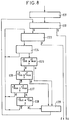
- FIG. 8 represents a flow diagram of a preferred example of implementation of the method according to the invention. It consists first of all of a step E21 consisting in determining the MIN-SUITE sequence made up of all the tasks ordered according to the increasing values of the lower bound tmin. This sequence will be used to apply the first principle stated above. To maximize the probability of quickly finding a permutation which satisfies all the constraints relating to all the tasks, the initial permutation is constituted by MIN-SUITE; and the permutations which will be checked next, by in case of failure, will be deducted from MIN-SUITE, by successive modifications.
- step E21 consists in determining the MAX-SUITE sequence, consisting of all the tasks ordered according to the increasing values of the upper bound t max . This sequence will be used to apply the second principle stated above, when it will be necessary to modify the initial permutation.
- a step E22 consists in verifying the current permutation, that is to say verifying whether it satisfies all the constraints relating to all the tasks.
- the current permutation is constituted by the initial permutation determined by step E21.
- This verification consists in successively taking each task in the order of the current permutation and in verifying that the execution interval [t deb , t end ] imposed by the position occupied by this task in the current permutation is compatible with the time interval [t min , t max ] imposed by the constraints relating to this task.
- the task for which this check is in progress is called the current task. If this check is positive for each task, it means that the current permutation is a success, noted S.
- step E22 finds a task, noted X, which is the first misplaced in the current permutation, it draws the conclusion, noted R, that it is necessary to seek a candidate candidate for a displacement to constitute a new permutation.
- the method then consists in executing a step E23 which searches for the task immediately preceding the current task X in the MAX-SUITE suite. If there is no such task, step E23 ends in failure, noted F.
- step E23 finds a candidate task Q immediately preceding the current task X in the MAX-SUITE sequence, the method then consists of a step E24 verifying that this task Q has already been considered to be well placed, during a step E21 anterior. All the tasks which are considered to be well placed are those which have a rank lower than that of the current task X, since the verification of step E22 is done according to the increasing ranks in the current permutation. Consequently, step E24 simply consists in verifying that the candidate task Q precedes the current task X in the current permutation. If step E24 determines that the task Q has not been considered as well placed, step E23 is repeated to search for another candidate task, immediately preceding the task Q in MAX-SUITE.
- the method consists in executing a step E25 which consists in comparing the instant t Q deb of the start of execution of the task Q with the instant t X max which is the upper bound of the time interval corresponding to the current task X.
- step E29 consisting in moving the task Q in the current permutation, to insert it between the current task X and the task following the task X in the current permutation.
- the tasks which were placed between Q and X, and the task X itself, are shifted by one row, towards the lower rows, to fill the space left free by Q. Consequently, task Q now occupies the position which was that of X.
- the method then consists in repeating step E22 to verify whether the new current permutation thus obtained satisfies all the constraints. Note that task Q and all other tasks that followed it have been moved.
- FIG. 9 illustrates by an example the case ⁇ . Execution intervals are shown in dotted lines when a conflict prevents execution, and in solid lines otherwise.
- Figure 10 shows that by moving the tasks Q and X respectively in the positions PS i-1 and PSj, the probability that the instant t deb (PS i-1 ) falls in the interval [t X min , t X max ] is greater than the probability that the instant t deb (P si ) had to fall in this same interval, because t deb systematically believes with the rank of the position PS.
- the figure shows that the end t X max of the segment corresponding to task X has approached an execution interval, the one that begins at the moment t deb (PSi-1) , and therefore more likely to have an intersection with such an interval.
- the end t Q max of the segment corresponding to task Q has non-zero chances of having an intersection with the rectangle representing the execution interval starting at time t deb (PSi). Therefore, the new permutation is more likely than the old one to satisfy all the constraints and it is therefore useful to try this new permutation.
- t deb (PS i-1 ) falls beyond t max , so there is still a conflict for task X. It is therefore necessary to make one or more other modifications to the current permutation .
- step E26 This consists in comparing the instant t Q end of the end of execution of the task Q, with the instant t X max which is the upper limit of the interval where the execution of the task X must begin. If t Q end ⁇ t X max , this case is noted ⁇ , and the method then consists in carrying out step E30 which moves the task Q and inserts it after the task X. The opposite case is noted ⁇ ⁇ . Other checks are necessary before being able to conclude that task Q is an interesting candidate task.
- FIG. 11 represents a task X in the position PS i and a task Q in the position PSj, such as the case ⁇ ⁇ and the case ⁇ are realized: the instant t Q end of the end of execution of the task Q, that is to say the end instant t (PSj) imposed by the position PSj of Q in the current permutation, is located beyond the instant t X max .
- step E27 consists in comparing the instant t Q max which is the upper bound of the time interval at which the execution of the task Q must begin, at the instant t X max which is the upper bound of l time interval at which the execution of task X must begin. If t Q max > t X max , this case is noted ⁇ , and the method then consists in then performing a step E28. Otherwise noted ⁇ ⁇ , and the method then consists in repeating step E23 because the candidate task Q has no chance of being interesting.
- Figures 13 and 14 illustrate by example the case ⁇ ⁇ .
- the limit t Q max is strictly less than the instant t X max .
- FIG. 13 represents the tasks X and Q displaced respectively in the positions PS i-1 and P si .
- This figure shows that the instant t Q max becomes closer to the instant t (PSi) deb than it was to the instant t (PSj) deb but the task Q has no chance of being able to be executed because t Q max is even further from t (PSi) deb than t Q max was . Since task Q is 100% likely to be misplaced, it is useless to try such a modification of the current permutation, this is why the next step is a step E23 of searching for another candidate task for a relocation.
- step E28 consists in comparing the instant t Q min which is the lower bound of the interval in which the execution of the task Q must begin, with the instant t X min which is the bound lower the time interval in which the execution of task X should begin.
- step E28 The purpose of this step E28 is to verify that the task Q is placed before the current task X in the MIN-SUITE suite, in order to be able to move the task Q after the task X. Otherwise, noted ⁇ ⁇ , the next step is a step E23 of searching for another candidate task for a displacement.
- next step is a step E29 moving the task Q after the task X; then a step E22 is reiterated to check whether all the constraints relating to the tasks of the current layer are satisfied.
- Fig. 15 illustrates an example where the cases ⁇ , ⁇ , ⁇ , ⁇ , are performed simultaneously.
- FIG. 16 represents the tasks X and Q displaced respectively in the positions PSi-1 and PSi, in an example where the constraints are such that they are effectively satisfied after this displacement: t deb (PSi) falls in the interval [t Q min , t Q max ] and t deb (PSi-1) fall in the interval [t X min , t X max ].
- Figures 17 to 26 illustrate the implementation of step E2 to schedule an example of a layer comprising 13 tasks: A, B, C, D, E, G, J, K, L, N, P, S, T.
- FIG. 17 represents on a time scale from 0 to 14 ms, the position of the execution intervals corresponding respectively to 13 positions PS1, ..., PS13.
- the sort tasks are executed in the order of positions PS1, ..., PS13, and each execution interval has a duration equal to 1 ms.
- Each task must satisfy one or more constraints which result in a single constraint: the start of the execution interval (black rectangle in Figure 17) must be located in a given time interval (black segments in Figure 18). In a borderline case it can start at the upper bound.
- Step E21 consists in determining the MIN-SUITE sequence consisting of all the tasks of the current layer, ordered according to the increasing values of the lower bound t min .
- MIN-SUITE N, J, S, D, E, B, T, A, K, P, L, C, G.
- the 13 tasks are represented in the order of MIN-SUITE, according to the direction of orientation of the ordinate axis.
- the so-called initial permutation which will be verified first will be that constituted by MIN-SUITE; and those which will be checked later, in the event of failure, will be deducted from MIN-SUITE by successive modifications.
- step E21 consists in determining the MAX-SUITE sequence, consisting of all the tasks of the current layer, ordered according to the increasing values of t max .
- This sequence will be used to apply the second principle stated above, when it will be necessary to modify the initial permutation.
- MAX-SUITE N, S, J, T, G, C, L, B, P, K, A, D, E.
- a step E22 consists in verifying the current permutation, that is to say verifying whether it satisfies all the constraints relating to the tasks of the layer considered.
- the current permutation is constituted by the initial permutation determined by step E21.
- the verification is done successively for each task, in the order of the current permutation: N, J, S, D, E, ..., G. If the verification is positive for a task it is considered to be well placed in the permutation, but its placement can be called into question later if this is necessary to satisfy other constraints.
- FIGS. 17 and 18 make it possible to conclude that there is no problem in executing tasks N, J, S, and D, respectively during the execution intervals represented in FIG. 17. They are therefore considered as well placed.
- the current permutation is: N J S D EBTAKPLCG where tasks considered to be well placed are underlined.
- Figure 19 illustrates the first conflict encountered during the initial swap check.
- black rectangles represent execution intervals for which there is no conflict between the constraints, and a dotted white rectangle represents the execution interval which is the cause of a conflict. It corresponds to position PS5, currently occupied by task E. This execution interval has nothing in common with the interval in which the execution of task E must begin.
- Step E23 then consists in searching in the MAX-SUITE sequence a task preceding task E, that is to say such that the limit t max has a higher value.
- MAX-SUITE N, S, J, T, G, C, L, B, P, K, A, D, E.
- Step E23 finds task D.
- Step E24 verifies that it is considered to be well placed, by checking that it has a rank lower than the rank of the current task E, in the current permutation. Then step E25 draws a conclusion ⁇ ⁇ . Then step E26 draws a conclusion ⁇ .
- Step E29 then moves D to the POS5 position and E moves back to the POS4 position.
- Step E22 verifies that the constraints relating to E and the following tasks are satisfied but notes that the constraints relating to D are no longer satisfied. The permutation tried is not suitable. It is not retained as a new current permutation.
- Step E23 would then find successively as a candidate task: A, K, P, B, L, C, G, T, J; and step E24 would retain task J.
- MAX-SUITE N, S, J, T, G, C, L, B, P, K, A, P.
- step E23 finds successively A, K, P, B, L, C, G, T as candidate task, which are rejected by step E24. Then step E23 finds task J.
- Step E24 verifies that the task J is considered to be well placed.
- Step E25 comes to the conclusion ⁇ ⁇ .
- Step E26 comes to the conclusion ⁇ ⁇ .
- Steps E27 and E28 arrive at the conclusion ⁇ and ⁇ . Consequently step E29 places task J in position PS5, in place of E.
- Tasks E, D and S move back one place, S being in position PS2, D in position PS3, and E in the PS4 position.
- the other tasks do not change places.
- Step E22 then consists in verifying that the tasks which have been moved check all the constraints relating to them, starting with the task of lowest rank among those displaced: S, then E, then D, then J. It checks then that there is no conflict between the constraints successively for tasks B, T, A, K.
- Figure 21 illustrates the new current permutation. It should be noted that for task K the execution interval begins at the exact moment when the interval in which the execution of task K must begin begins. There is no conflict, but the constraints are barely satisfied.
- the state of the current permutation is: N , S , E , D , J , B , T , A , K , P, L, C, G.
- FIG. 22 shows that a conflict appears for task P.
- Step E23 is then repeated to determine in the MAX-SUITE sequence the task immediately preceding task P in this sequence. It finds task B.
- Step E24 verifies that task B is one of the tasks which are considered to be well placed.
- Steps E25 and E26 draw conclusions ⁇ ⁇ then ⁇ ⁇ .
- Step E23 is then repeated to search for another candidate task in the MAX-SUITE sequence. Indeed, the segment representing the time interval corresponding to B would have no point of intersection with the execution interval [9 ms, 10 ms] corresponding to position POS10, if task B were moved to this position . Consequently the constraints relating to B would not be satisfied.
- Step E23 then successively finds the tasks L, C, G but step E24 rejects them because they are not considered to be well placed in the permutation. Finally steps E23 and E24 find task T. Steps E25 to E28 successively draw conclusions ⁇ ⁇ , ⁇ ⁇ , ⁇ , ⁇ . Step E29 moves T to position POS10. Tasks P, K, A move back respectively to positions POS9, POS8, POS7.
- Step E22 then verifies that the constraints relating to the displaced tasks A, K, P, T, and the following ones, are satisfied.
- the new current permutation is: N , S , E , D , J , B , A , K , P , T , L, C, G
- step E22 finds that the constraints relating to the task L are not satisfied.
- Step E23 finds task T and step E24 verifies that it is considered to be well placed. Step E25 and the following ones can therefore be executed. They draw conclusions ⁇ ⁇ , then ⁇ ⁇ , then ⁇ and ⁇ . Step E29 can then be executed. It places task T in position PS 11 which was occupied by task L. Task L moves back one place. Step E22 verifies that the constraints relating to the displaced tasks L and T are satisfied. Therefore the current permutation becomes: N , S , E , D , J , V , A , K , P , L , T , C, G
- the new current permutation is: N , S , E , D , J , B , A , K , P , L , C , T , G
- step E22 finds that there is a conflict between the constraints relating to task G.
- Step E23 determines a task, T, which precedes task G immediately in the MAX-SUITE sequence .
- Step E24 verifies that the task T is considered to be well placed in the permutation.
- Step E29 moves T after G in the permutation, which amounts to permuting T and G.
- step E22 verifies that all the constraints relating to the displaced tasks G and T are satisfied.
- the new current permutation is: N , S , E , D , J , B , A , K , P , L , C , G , T.
- step E2 ends in success S.
Landscapes
- Engineering & Computer Science (AREA)
- Business, Economics & Management (AREA)
- Human Resources & Organizations (AREA)
- Theoretical Computer Science (AREA)
- Physics & Mathematics (AREA)
- Software Systems (AREA)
- Economics (AREA)
- Entrepreneurship & Innovation (AREA)
- Strategic Management (AREA)
- General Physics & Mathematics (AREA)
- Educational Administration (AREA)
- Quality & Reliability (AREA)
- Tourism & Hospitality (AREA)
- Operations Research (AREA)
- General Business, Economics & Management (AREA)
- Marketing (AREA)
- Game Theory and Decision Science (AREA)
- Development Economics (AREA)
- General Engineering & Computer Science (AREA)
- Management, Administration, Business Operations System, And Electronic Commerce (AREA)
- Mobile Radio Communication Systems (AREA)
- Computer And Data Communications (AREA)
- General Factory Administration (AREA)
Applications Claiming Priority (2)
| Application Number | Priority Date | Filing Date | Title |
|---|---|---|---|
| FR9409952A FR2723653B1 (fr) | 1994-08-11 | 1994-08-11 | Procede pour ordonnancer des taches successives qui ne subissent que des contraintes du type delais |
| FR9409952 | 1994-08-11 |
Publications (2)
| Publication Number | Publication Date |
|---|---|
| EP0697657A1 true EP0697657A1 (de) | 1996-02-21 |
| EP0697657B1 EP0697657B1 (de) | 2000-01-12 |
Family
ID=9466264
Family Applications (1)
| Application Number | Title | Priority Date | Filing Date |
|---|---|---|---|
| EP95401867A Expired - Lifetime EP0697657B1 (de) | 1994-08-11 | 1995-08-09 | Verfahren für die Ablauffolgeplanung von aufeinanderfolgenden Aufgaben mit Zeitzwangsbedingungen |
Country Status (8)
| Country | Link |
|---|---|
| US (1) | US5606695A (de) |
| EP (1) | EP0697657B1 (de) |
| JP (1) | JPH0869383A (de) |
| AT (1) | ATE188787T1 (de) |
| DE (1) | DE69514444T2 (de) |
| DK (1) | DK0697657T3 (de) |
| ES (1) | ES2141313T3 (de) |
| FR (1) | FR2723653B1 (de) |
Cited By (1)
| Publication number | Priority date | Publication date | Assignee | Title |
|---|---|---|---|---|
| US6151538A (en) * | 1997-05-23 | 2000-11-21 | Rolls-Royce Plc | Control system |
Families Citing this family (45)
| Publication number | Priority date | Publication date | Assignee | Title |
|---|---|---|---|---|
| JPH0954699A (ja) | 1995-08-11 | 1997-02-25 | Fujitsu Ltd | 計算機のプロセススケジューラ |
| DE19530483A1 (de) * | 1995-08-18 | 1997-02-20 | Siemens Ag | Einrichtung und Verfahren zur Echtzeit-Verarbeitung einer Mehrzahl von Tasks |
| US6012080A (en) * | 1996-03-27 | 2000-01-04 | Lucent Technologies Inc. | Method and apparatus for providing enhanced pay per view in a video server |
| US5964829A (en) * | 1996-03-27 | 1999-10-12 | Lucent Technologies Inc. | Method and apparatus for providing enhanced pay per view in a video server employing a coarse-grained striping scheme |
| US5745113A (en) * | 1996-04-03 | 1998-04-28 | Institute For Research On Learning | Representing work practices |
| US6317774B1 (en) | 1997-01-09 | 2001-11-13 | Microsoft Corporation | Providing predictable scheduling of programs using a repeating precomputed schedule |
| CA2228574A1 (en) * | 1997-06-05 | 1999-08-02 | Attention Control Systems, Inc. | An automatic planning and cueing system and method |
| US6035278A (en) * | 1997-07-08 | 2000-03-07 | Netscape Communications Corporation | Method and system for schedule and task management |
| US6144942A (en) * | 1998-04-28 | 2000-11-07 | Micron Electronics, Inc. | Method for notifying an individual of a previously scheduled event |
| US6092120A (en) | 1998-06-26 | 2000-07-18 | Sun Microsystems, Inc. | Method and apparatus for timely delivery of a byte code and serialized objects stream |
| DE60015211T2 (de) * | 1999-03-15 | 2005-10-27 | Océ-Technologies B.V. | Zeitplanverfahren und Planer für eine modulare Maschine |
| JP3756344B2 (ja) | 1999-05-11 | 2006-03-15 | 京セラ株式会社 | マルチモード携帯電話装置 |
| US8788308B1 (en) * | 2004-03-29 | 2014-07-22 | West Corporation | Employee scheduling and schedule modification method and apparatus |
| US6738972B1 (en) * | 1999-12-30 | 2004-05-18 | Opentv, Inc. | Method for flow scheduling |
| JP2004502235A (ja) * | 2000-06-27 | 2004-01-22 | コーニンクレッカ フィリップス エレクトロニクス エヌ ヴィ | スケジュール決定方法、スケジューラ及びシステム |
| DE10065498B4 (de) * | 2000-12-28 | 2005-07-07 | Robert Bosch Gmbh | Verfahren und Vorrichtung zur Rekonstruktion des Prozessablaufs eines Steuerprogramms |
| US6918115B2 (en) * | 2001-02-16 | 2005-07-12 | Microsoft Corporation | Method and apparatus for synchronization of periodic processes |
| US20020143600A1 (en) * | 2001-03-08 | 2002-10-03 | Dugan Valerie G. | Internet-based appointment scheduling |
| US8170980B1 (en) | 2002-10-11 | 2012-05-01 | The United States Of America As Represented By The Secretary Of The Navy | Universal software architecture for decision support |
| DE102005010580A1 (de) * | 2005-03-04 | 2006-09-07 | Inchron Gmbh | Verfahren zur Echtzeitanalyse eines Systems |
| US20080216012A1 (en) * | 2005-08-26 | 2008-09-04 | United Space Alliance, Llc | Instruction and training tool |
| US8103533B2 (en) | 2005-08-26 | 2012-01-24 | United Space Alliance, Llc | Automated resource planning tool and user interface |
| US7315996B2 (en) * | 2005-09-22 | 2008-01-01 | International Business Machines Corporation | Method and system for performing heuristic constraint simplification |
| US8495613B2 (en) * | 2005-12-22 | 2013-07-23 | Microsoft Corporation | Program execution service windows |
| SG136862A1 (en) * | 2006-04-21 | 2007-11-29 | Oce Tech Bv | Variable speed printing |
| TWI324747B (en) * | 2006-06-08 | 2010-05-11 | Wistron Corp | Method for preventing process collision of micro controller |
| CN100507854C (zh) * | 2006-06-19 | 2009-07-01 | 纬创资通股份有限公司 | 避免微控制器执行程序碰撞的方法 |
| US7610151B2 (en) | 2006-06-27 | 2009-10-27 | Microsoft Corporation | Collaborative route planning for generating personalized and context-sensitive routing recommendations |
| US8793066B2 (en) | 2006-06-27 | 2014-07-29 | Microsoft Corporation | Route monetization |
| US7706964B2 (en) * | 2006-06-30 | 2010-04-27 | Microsoft Corporation | Inferring road speeds for context-sensitive routing |
| US7739040B2 (en) * | 2006-06-30 | 2010-06-15 | Microsoft Corporation | Computation of travel routes, durations, and plans over multiple contexts |
| US7617042B2 (en) * | 2006-06-30 | 2009-11-10 | Microsoft Corporation | Computing and harnessing inferences about the timing, duration, and nature of motion and cessation of motion with applications to mobile computing and communications |
| US8126641B2 (en) * | 2006-06-30 | 2012-02-28 | Microsoft Corporation | Route planning with contingencies |
| US8301473B2 (en) | 2006-08-24 | 2012-10-30 | United Space Alliance, Llc | Stowage and center of gravity verification and assessment tool |
| US20090157540A1 (en) * | 2007-12-14 | 2009-06-18 | Microsoft Corporation | Destination auctioned through business of interest |
| US20090157498A1 (en) * | 2007-12-14 | 2009-06-18 | Microsoft Corporation | Generational intelligent navigation synchronization or update |
| US20090210302A1 (en) * | 2008-02-19 | 2009-08-20 | Microsoft Corporation | Route reward augmentation |
| US20090210242A1 (en) * | 2008-02-19 | 2009-08-20 | Microsoft Corporation | Load balance payment |
| US20090210142A1 (en) * | 2008-02-19 | 2009-08-20 | Microsoft Corporation | Safe route configuration |
| US9842317B2 (en) | 2012-05-28 | 2017-12-12 | Brandon Jordan | Methods, systems, and apparatus for scheduling appointments |
| US9208591B2 (en) | 2013-04-18 | 2015-12-08 | International Business Machines Corporation | Providing user controlled ability to determine data level of detail in a graph |
| US20150012323A1 (en) * | 2013-07-02 | 2015-01-08 | Oracle International Corporation | Generating multiple optimal daily schedules for multiple time periods in a day and for multiple daily patterns |
| US10241654B2 (en) * | 2013-12-20 | 2019-03-26 | Dassault Systemes Americas Corp. | Computer method and apparatus for automated scheduling |
| KR102325272B1 (ko) * | 2019-04-24 | 2021-11-11 | 한국원자력연구원 | 수행시간 기반의 원전 운전원 신뢰도 평가 장치 및 그 방법 |
| WO2021011001A1 (en) | 2019-07-18 | 2021-01-21 | Hewlett-Packard Development Company, L.P. | Adaptive interpage delays |
-
1994
- 1994-08-11 FR FR9409952A patent/FR2723653B1/fr not_active Expired - Fee Related
-
1995
- 1995-08-02 US US08/510,533 patent/US5606695A/en not_active Expired - Fee Related
- 1995-08-09 AT AT95401867T patent/ATE188787T1/de not_active IP Right Cessation
- 1995-08-09 DK DK95401867T patent/DK0697657T3/da active
- 1995-08-09 ES ES95401867T patent/ES2141313T3/es not_active Expired - Lifetime
- 1995-08-09 DE DE69514444T patent/DE69514444T2/de not_active Expired - Fee Related
- 1995-08-09 EP EP95401867A patent/EP0697657B1/de not_active Expired - Lifetime
- 1995-08-11 JP JP7206069A patent/JPH0869383A/ja active Pending
Non-Patent Citations (3)
| Title |
|---|
| BRINKLEY SPRUNT ET AL. :: "Aperiodic Task Scheduling for Hard-Real-Time Systems", REAL TIME SYSTEMS, vol. 1, no. 1, June 1989 (1989-06-01), DORDRECHT, NL, pages 27 - 60 * |
| KRITHI RAMAMRITHAM ET AL.:: "Scheduling Algorithms and Operating Systems Support for Real-Time Systems", PROCEEDINGS OF THE IEEE, vol. 82, no. 1, January 1994 (1994-01-01), NEW YORK, US, pages 55 - 67, XP000435881, DOI: doi:10.1109/5.259426 * |
| WEI ZHAO ET AL.:: "Scheduling Tasks with Resource Requirements in Hard Real-Time Systems", IEEE TRANSACTIONS ON SOFTWARE ENGINEERING, vol. SE-13, no. 5, May 1987 (1987-05-01), NEW YORK US, pages 564 - 576 * |
Cited By (1)
| Publication number | Priority date | Publication date | Assignee | Title |
|---|---|---|---|---|
| US6151538A (en) * | 1997-05-23 | 2000-11-21 | Rolls-Royce Plc | Control system |
Also Published As
| Publication number | Publication date |
|---|---|
| DK0697657T3 (da) | 2000-05-15 |
| ATE188787T1 (de) | 2000-01-15 |
| US5606695A (en) | 1997-02-25 |
| ES2141313T3 (es) | 2000-03-16 |
| JPH0869383A (ja) | 1996-03-12 |
| DE69514444D1 (de) | 2000-02-17 |
| FR2723653B1 (fr) | 1996-09-13 |
| DE69514444T2 (de) | 2000-08-03 |
| EP0697657B1 (de) | 2000-01-12 |
| FR2723653A1 (fr) | 1996-02-16 |
Similar Documents
| Publication | Publication Date | Title |
|---|---|---|
| EP0697657B1 (de) | Verfahren für die Ablauffolgeplanung von aufeinanderfolgenden Aufgaben mit Zeitzwangsbedingungen | |
| EP0697656B1 (de) | Verfahren für die Ablauffolgeplanung von aufeinanderfolgenden Aufgaben | |
| FR3072197B1 (fr) | Procede d'execution de plans de sequencement assurant une communication a faible latence entre taches temps-reel | |
| EP3674998B1 (de) | Entwicklungsmethode eines kompilierungsverfahrens eines quantenschaltkreises auf einem quantenprozessor | |
| EP0527664B1 (de) | Hilfsverfahren für die Entwicklung einer miteinander kommunizierender Automatengruppe | |
| EP3674996B1 (de) | Entwicklungsmethode eines kompilierungsverfahrens eines quantenschaltkreises auf einem quantenprozessor, und entsprechendes verfahren | |
| EP3674997A1 (de) | Kompilationsverfahren eines quantenschaltkreises auf einem quantenprozessor mit in einer falle gefangenen ionen | |
| FR3091388A1 (fr) | Procédé de compilation d’un circuit quantique sur un processeur quantique à ions piégés | |
| EP4071672A1 (de) | Klassifizierung von unbekannten fehlern in einem elektronischen kommunikationssystem | |
| CA1257006A (fr) | Procede et dispositif pour la transmission de messages entre differentes stations, a travers un reseau local a diffusion | |
| EP4186009B1 (de) | Verfahren zur zuweisung logischer qubits eines quantenalgorithmus in einem quantenprozessor | |
| EP3084602B1 (de) | Verfahren zum zusammenstellen und ausführen eines echtzeit-aufgabenabfolgeplans | |
| EP0678811B1 (de) | Verfahren zur Verklemmungserkennung in einem Multiprozessorsystem mit gemeinschaftlichen Speicher | |
| FR2965077A1 (fr) | Procede de gestion de taches dans un microprocesseur ou un ensemble de microprocesseurs | |
| FR3159688A1 (fr) | Procédé de mitigation d'interférences temporelles par exclusion temporelles configurées par compilation | |
| EP2756398B1 (de) | Verfahren, vorrichtung und computerprogramm zur dynamischen ressourcenzuweisung einer gruppe zur durchführung von anwendungsprozessen | |
| EP1034476B1 (de) | Verfahren zur funktionsprüfung eines systems | |
| FR3071334A1 (fr) | Procede pour assurer la stabilite des donnees d’un processeur multicoeur d’un vehicule automobile | |
| WO2022207424A1 (fr) | Procede d'implementation d'un module logiciel defini par un graphe oriente non cyclique non imbrique en environnement multi-cœur | |
| EP1901555A1 (de) | Deinterlacing von Bildern | |
| EP4439326A1 (de) | Recheneinheit einer konfigurierbaren integrierten schaltung zur verbesserung der datenflussverwaltung | |
| FR3131022A1 (fr) | Procede de determination d une grandeur physique et systeme de determination associe. | |
| FR3149817A1 (fr) | Procédé de programmation comportementale de robot dans une architecture de réseau robotique | |
| WO2018185442A1 (fr) | Dispositif de placement amélioré | |
| FR2767396A1 (fr) | Procede d'imbrication de pieces elementaires dans un ou plusieurs panneaux a usiner |
Legal Events
| Date | Code | Title | Description |
|---|---|---|---|
| PUAI | Public reference made under article 153(3) epc to a published international application that has entered the european phase |
Free format text: ORIGINAL CODE: 0009012 |
|
| AK | Designated contracting states |
Kind code of ref document: A1 Designated state(s): AT BE CH DE DK ES GB IT LI NL SE |
|
| 17P | Request for examination filed |
Effective date: 19960629 |
|
| GRAG | Despatch of communication of intention to grant |
Free format text: ORIGINAL CODE: EPIDOS AGRA |
|
| GRAG | Despatch of communication of intention to grant |
Free format text: ORIGINAL CODE: EPIDOS AGRA |
|
| GRAH | Despatch of communication of intention to grant a patent |
Free format text: ORIGINAL CODE: EPIDOS IGRA |
|
| 17Q | First examination report despatched |
Effective date: 19990628 |
|
| GRAH | Despatch of communication of intention to grant a patent |
Free format text: ORIGINAL CODE: EPIDOS IGRA |
|
| GRAH | Despatch of communication of intention to grant a patent |
Free format text: ORIGINAL CODE: EPIDOS IGRA |
|
| GRAA | (expected) grant |
Free format text: ORIGINAL CODE: 0009210 |
|
| AK | Designated contracting states |
Kind code of ref document: B1 Designated state(s): AT BE CH DE DK ES GB IT LI NL SE |
|
| REF | Corresponds to: |
Ref document number: 188787 Country of ref document: AT Date of ref document: 20000115 Kind code of ref document: T |
|
| REG | Reference to a national code |
Ref country code: CH Ref legal event code: EP |
|
| REF | Corresponds to: |
Ref document number: 69514444 Country of ref document: DE Date of ref document: 20000217 |
|
| ITF | It: translation for a ep patent filed | ||
| REG | Reference to a national code |
Ref country code: ES Ref legal event code: FG2A Ref document number: 2141313 Country of ref document: ES Kind code of ref document: T3 |
|
| REG | Reference to a national code |
Ref country code: CH Ref legal event code: NV Representative=s name: CABINET ROLAND NITHARDT CONSEILS EN PROPRIETE INDU |
|
| GBT | Gb: translation of ep patent filed (gb section 77(6)(a)/1977) |
Effective date: 20000310 |
|
| REG | Reference to a national code |
Ref country code: DK Ref legal event code: T3 |
|
| PLBE | No opposition filed within time limit |
Free format text: ORIGINAL CODE: 0009261 |
|
| STAA | Information on the status of an ep patent application or granted ep patent |
Free format text: STATUS: NO OPPOSITION FILED WITHIN TIME LIMIT |
|
| 26N | No opposition filed | ||
| REG | Reference to a national code |
Ref country code: GB Ref legal event code: IF02 |
|
| PGFP | Annual fee paid to national office [announced via postgrant information from national office to epo] |
Ref country code: DE Payment date: 20050818 Year of fee payment: 11 Ref country code: AT Payment date: 20050818 Year of fee payment: 11 |
|
| PGFP | Annual fee paid to national office [announced via postgrant information from national office to epo] |
Ref country code: SE Payment date: 20050819 Year of fee payment: 11 |
|
| PGFP | Annual fee paid to national office [announced via postgrant information from national office to epo] |
Ref country code: GB Payment date: 20050822 Year of fee payment: 11 |
|
| PGFP | Annual fee paid to national office [announced via postgrant information from national office to epo] |
Ref country code: NL Payment date: 20050823 Year of fee payment: 11 Ref country code: DK Payment date: 20050823 Year of fee payment: 11 Ref country code: CH Payment date: 20050823 Year of fee payment: 11 Ref country code: BE Payment date: 20050823 Year of fee payment: 11 |
|
| PGFP | Annual fee paid to national office [announced via postgrant information from national office to epo] |
Ref country code: ES Payment date: 20050919 Year of fee payment: 11 |
|
| PG25 | Lapsed in a contracting state [announced via postgrant information from national office to epo] |
Ref country code: AT Free format text: LAPSE BECAUSE OF NON-PAYMENT OF DUE FEES Effective date: 20060809 |
|
| PG25 | Lapsed in a contracting state [announced via postgrant information from national office to epo] |
Ref country code: SE Free format text: LAPSE BECAUSE OF NON-PAYMENT OF DUE FEES Effective date: 20060810 |
|
| PG25 | Lapsed in a contracting state [announced via postgrant information from national office to epo] |
Ref country code: LI Free format text: LAPSE BECAUSE OF NON-PAYMENT OF DUE FEES Effective date: 20060831 Ref country code: DK Free format text: LAPSE BECAUSE OF NON-PAYMENT OF DUE FEES Effective date: 20060831 Ref country code: CH Free format text: LAPSE BECAUSE OF NON-PAYMENT OF DUE FEES Effective date: 20060831 Ref country code: BE Free format text: LAPSE BECAUSE OF NON-PAYMENT OF DUE FEES Effective date: 20060831 |
|
| PGFP | Annual fee paid to national office [announced via postgrant information from national office to epo] |
Ref country code: IT Payment date: 20060831 Year of fee payment: 12 |
|
| PG25 | Lapsed in a contracting state [announced via postgrant information from national office to epo] |
Ref country code: NL Free format text: LAPSE BECAUSE OF NON-PAYMENT OF DUE FEES Effective date: 20070301 Ref country code: DE Free format text: LAPSE BECAUSE OF NON-PAYMENT OF DUE FEES Effective date: 20070301 |
|
| REG | Reference to a national code |
Ref country code: DK Ref legal event code: EBP |
|
| REG | Reference to a national code |
Ref country code: CH Ref legal event code: PL |
|
| EUG | Se: european patent has lapsed | ||
| GBPC | Gb: european patent ceased through non-payment of renewal fee |
Effective date: 20060809 |
|
| NLV4 | Nl: lapsed or anulled due to non-payment of the annual fee |
Effective date: 20070301 |
|
| REG | Reference to a national code |
Ref country code: ES Ref legal event code: FD2A Effective date: 20060810 |
|
| PG25 | Lapsed in a contracting state [announced via postgrant information from national office to epo] |
Ref country code: GB Free format text: LAPSE BECAUSE OF NON-PAYMENT OF DUE FEES Effective date: 20060809 |
|
| BERE | Be: lapsed |
Owner name: *CEGELEC Effective date: 20060831 |
|
| PG25 | Lapsed in a contracting state [announced via postgrant information from national office to epo] |
Ref country code: ES Free format text: LAPSE BECAUSE OF NON-PAYMENT OF DUE FEES Effective date: 20060810 |
|
| PG25 | Lapsed in a contracting state [announced via postgrant information from national office to epo] |
Ref country code: IT Free format text: LAPSE BECAUSE OF NON-PAYMENT OF DUE FEES Effective date: 20070809 |