EP0697744A1 - Dispositif électroluminescent organique - Google Patents
Dispositif électroluminescent organique Download PDFInfo
- Publication number
- EP0697744A1 EP0697744A1 EP95202173A EP95202173A EP0697744A1 EP 0697744 A1 EP0697744 A1 EP 0697744A1 EP 95202173 A EP95202173 A EP 95202173A EP 95202173 A EP95202173 A EP 95202173A EP 0697744 A1 EP0697744 A1 EP 0697744A1
- Authority
- EP
- European Patent Office
- Prior art keywords
- organic
- type
- layer
- rare earth
- component according
- Prior art date
- Legal status (The legal status is an assumption and is not a legal conclusion. Google has not performed a legal analysis and makes no representation as to the accuracy of the status listed.)
- Granted
Links
Images

Classifications
-
- H—ELECTRICITY
- H10—SEMICONDUCTOR DEVICES; ELECTRIC SOLID-STATE DEVICES NOT OTHERWISE PROVIDED FOR
- H10F—INORGANIC SEMICONDUCTOR DEVICES SENSITIVE TO INFRARED RADIATION, LIGHT, ELECTROMAGNETIC RADIATION OF SHORTER WAVELENGTH OR CORPUSCULAR RADIATION
- H10F39/00—Integrated devices, or assemblies of multiple devices, comprising at least one element covered by group H10F30/00, e.g. radiation detectors comprising photodiode arrays
- H10F39/10—Integrated devices
- H10F39/12—Image sensors
- H10F39/191—Photoconductor image sensors
- H10F39/195—X-ray, gamma-ray or corpuscular radiation imagers
-
- H—ELECTRICITY
- H10—SEMICONDUCTOR DEVICES; ELECTRIC SOLID-STATE DEVICES NOT OTHERWISE PROVIDED FOR
- H10K—ORGANIC ELECTRIC SOLID-STATE DEVICES
- H10K50/00—Organic light-emitting devices
- H10K50/10—OLEDs or polymer light-emitting diodes [PLED]
- H10K50/11—OLEDs or polymer light-emitting diodes [PLED] characterised by the electroluminescent [EL] layers
-
- H—ELECTRICITY
- H10—SEMICONDUCTOR DEVICES; ELECTRIC SOLID-STATE DEVICES NOT OTHERWISE PROVIDED FOR
- H10K—ORGANIC ELECTRIC SOLID-STATE DEVICES
- H10K50/00—Organic light-emitting devices
- H10K50/80—Constructional details
-
- H—ELECTRICITY
- H10—SEMICONDUCTOR DEVICES; ELECTRIC SOLID-STATE DEVICES NOT OTHERWISE PROVIDED FOR
- H10K—ORGANIC ELECTRIC SOLID-STATE DEVICES
- H10K59/00—Integrated devices, or assemblies of multiple devices, comprising at least one organic light-emitting element covered by group H10K50/00
-
- H—ELECTRICITY
- H10—SEMICONDUCTOR DEVICES; ELECTRIC SOLID-STATE DEVICES NOT OTHERWISE PROVIDED FOR
- H10K—ORGANIC ELECTRIC SOLID-STATE DEVICES
- H10K59/00—Integrated devices, or assemblies of multiple devices, comprising at least one organic light-emitting element covered by group H10K50/00
- H10K59/60—OLEDs integrated with inorganic light-sensitive elements, e.g. with inorganic solar cells or inorganic photodiodes
-
- H—ELECTRICITY
- H10—SEMICONDUCTOR DEVICES; ELECTRIC SOLID-STATE DEVICES NOT OTHERWISE PROVIDED FOR
- H10K—ORGANIC ELECTRIC SOLID-STATE DEVICES
- H10K85/00—Organic materials used in the body or electrodes of devices covered by this subclass
- H10K85/30—Coordination compounds
- H10K85/351—Metal complexes comprising lanthanides or actinides, e.g. comprising europium
-
- H—ELECTRICITY
- H10—SEMICONDUCTOR DEVICES; ELECTRIC SOLID-STATE DEVICES NOT OTHERWISE PROVIDED FOR
- H10K—ORGANIC ELECTRIC SOLID-STATE DEVICES
- H10K85/00—Organic materials used in the body or electrodes of devices covered by this subclass
- H10K85/60—Organic compounds having low molecular weight
- H10K85/631—Amine compounds having at least two aryl rest on at least one amine-nitrogen atom, e.g. triphenylamine
-
- H—ELECTRICITY
- H10—SEMICONDUCTOR DEVICES; ELECTRIC SOLID-STATE DEVICES NOT OTHERWISE PROVIDED FOR
- H10F—INORGANIC SEMICONDUCTOR DEVICES SENSITIVE TO INFRARED RADIATION, LIGHT, ELECTROMAGNETIC RADIATION OF SHORTER WAVELENGTH OR CORPUSCULAR RADIATION
- H10F55/00—Radiation-sensitive semiconductor devices covered by groups H10F10/00, H10F19/00 or H10F30/00 being structurally associated with electric light sources and electrically or optically coupled thereto
- H10F55/18—Radiation-sensitive semiconductor devices covered by groups H10F10/00, H10F19/00 or H10F30/00 being structurally associated with electric light sources and electrically or optically coupled thereto wherein the radiation-sensitive semiconductor devices and the electric light source share a common body having dual-functionality of light emission and light detection
-
- H—ELECTRICITY
- H10—SEMICONDUCTOR DEVICES; ELECTRIC SOLID-STATE DEVICES NOT OTHERWISE PROVIDED FOR
- H10H—INORGANIC LIGHT-EMITTING SEMICONDUCTOR DEVICES HAVING POTENTIAL BARRIERS
- H10H29/00—Integrated devices, or assemblies of multiple devices, comprising at least one light-emitting semiconductor element covered by group H10H20/00
- H10H29/10—Integrated devices comprising at least one light-emitting semiconductor component covered by group H10H20/00
- H10H29/14—Integrated devices comprising at least one light-emitting semiconductor component covered by group H10H20/00 comprising multiple light-emitting semiconductor components
- H10H29/142—Two-dimensional arrangements, e.g. asymmetric LED layout
-
- H—ELECTRICITY
- H10—SEMICONDUCTOR DEVICES; ELECTRIC SOLID-STATE DEVICES NOT OTHERWISE PROVIDED FOR
- H10K—ORGANIC ELECTRIC SOLID-STATE DEVICES
- H10K2101/00—Properties of the organic materials covered by group H10K85/00
- H10K2101/10—Triplet emission
-
- H—ELECTRICITY
- H10—SEMICONDUCTOR DEVICES; ELECTRIC SOLID-STATE DEVICES NOT OTHERWISE PROVIDED FOR
- H10K—ORGANIC ELECTRIC SOLID-STATE DEVICES
- H10K2102/00—Constructional details relating to the organic devices covered by this subclass
- H10K2102/10—Transparent electrodes, e.g. using graphene
- H10K2102/101—Transparent electrodes, e.g. using graphene comprising transparent conductive oxides [TCO]
- H10K2102/103—Transparent electrodes, e.g. using graphene comprising transparent conductive oxides [TCO] comprising indium oxides, e.g. ITO
-
- H—ELECTRICITY
- H10—SEMICONDUCTOR DEVICES; ELECTRIC SOLID-STATE DEVICES NOT OTHERWISE PROVIDED FOR
- H10K—ORGANIC ELECTRIC SOLID-STATE DEVICES
- H10K59/00—Integrated devices, or assemblies of multiple devices, comprising at least one organic light-emitting element covered by group H10K50/00
- H10K59/10—OLED displays
- H10K59/17—Passive-matrix OLED displays
-
- H—ELECTRICITY
- H10—SEMICONDUCTOR DEVICES; ELECTRIC SOLID-STATE DEVICES NOT OTHERWISE PROVIDED FOR
- H10K—ORGANIC ELECTRIC SOLID-STATE DEVICES
- H10K85/00—Organic materials used in the body or electrodes of devices covered by this subclass
- H10K85/10—Organic polymers or oligomers
- H10K85/141—Organic polymers or oligomers comprising aliphatic or olefinic chains, e.g. poly N-vinylcarbazol, PVC or PTFE
- H10K85/146—Organic polymers or oligomers comprising aliphatic or olefinic chains, e.g. poly N-vinylcarbazol, PVC or PTFE poly N-vinylcarbazol; Derivatives thereof
-
- Y—GENERAL TAGGING OF NEW TECHNOLOGICAL DEVELOPMENTS; GENERAL TAGGING OF CROSS-SECTIONAL TECHNOLOGIES SPANNING OVER SEVERAL SECTIONS OF THE IPC; TECHNICAL SUBJECTS COVERED BY FORMER USPC CROSS-REFERENCE ART COLLECTIONS [XRACs] AND DIGESTS
- Y10—TECHNICAL SUBJECTS COVERED BY FORMER USPC
- Y10S—TECHNICAL SUBJECTS COVERED BY FORMER USPC CROSS-REFERENCE ART COLLECTIONS [XRACs] AND DIGESTS
- Y10S428/00—Stock material or miscellaneous articles
- Y10S428/917—Electroluminescent
Definitions
- the invention relates to an organic, electro-luminescent component, e.g. Electroluminescent diodes (LED) for illuminated displays, lights, solid-state image intensifiers, high-performance monitors or television screens.
- LED Electroluminescent diodes
- LEDs are usually semiconductor diodes, i.e. diodes for their construction inorganic semiconductors such as doped zinc sulfide, silicon, germanium or III-V semiconductors, e.g. InP, GaAs, GaAlAs, GaP or GaN can be used with appropriate doping.
- These semiconductor diodes contain a p-doped crystal zone and an n-doped crystal zone.
- an n-conducting basic crystal is first produced by appropriate doping of the semiconductor.
- a p-zone with a thickness of only 1 ⁇ m and a high degree of doping is left on it, i.e. large hole density, grow up.
- the p-layer is covered with a transparent electrode, the n-layer with a normal metal electrode.
- a voltage is applied in the forward direction, electrons from the n region and holes from the p region migrate into the pn boundary layer and recombine there, i.e. the electrons fill the holes in the valence band.
- the energy released during recombination is emitted in the form of light quanta.
- the color of the emitted light depends on the semiconductor used and its doping.
- Electroluminescent components with luminous layers that are made of organic materials are clearly superior to light sources made of inorganic materials in some properties.
- One advantage is their easy formability and high elasticity, which makes new applications possible, for example, for illuminated displays and screens. These layers can easily be produced as large, flat and very thin layers, for which the use of materials is also low. They are also characterized by a remarkably high brightness with a low control voltage.
- the color of the emitted light can be varied over a wide range from approximately 400 nm to approximately 650 nm by selecting the luminescent substance. These colors stand out due to their luminance.
- an electroluminescent component which comprises a layer sequence of (a) a substrate which is transparent to visible light, (b) a first electrode which is transparent to visible light, (c) a p conductive layer which is transparent to visible light, (d) a luminescent layer which contains metallo-organic complexes of the lanthanoids and (e) a second electrode.
- the p-conducting layer can be an organic or inorganic semiconductor of the p-type and the metallo-organic complexes can be embedded in a membrane which consists of compounds which can form an add-on complex with the excited state of the said metallo-organic complex .
- Such an electroluminescent component is characterized by monochromatic radiation.
- a disadvantage of the above components is their low efficiency. According to the results of various working groups that became known, less than a few thousandths of the power supplied was illuminated in the first prototypes converted, meanwhile the efficiency for the internal quantum yield could be increased to about 4% (Nature, Vol.365, p.628), the external quantum yield to 4.2% (J.Appl.Phys.72, 1957 (1992)) .
- the invention is based on the idea that it should be made possible to increase the luminous efficacy of organic, electroluminescent components in that the excitons formed during the recombination of electrons and holes are not only the singlet excitons as in the prior art but also the triplet excitons can be used for light excitation.
- An organic electroluminescent component according to the invention is therefore distinguished by a surprisingly increased luminous efficacy, moreover it has very good thermal stability and can be produced using simple processes.
- a p-type organic material and the luminescent material are contained in a first, homogeneous layer and an n-type organic material is contained in a second layer, the lowest triplet state of the p -conductive organic material is lower than that of the n -conductive organic material.
- the luminescence-generating processes have a particularly high efficiency.
- a p-conducting organic material is contained in a first layer and an n-conducting organic material and the luminescent material are contained in a second, homogeneous layer, wherein the lowest triplet state of the n-type organic material is lower than that of the p-type organic material.
- This configuration also shows a very good light output.
- a p-type organic material with the luminescent material is contained in a first homogeneous layer and an n-type organic material with the luminescent material in a second homogeneous layer.
- This configuration shows the best efficiency with approximately the same position of the energy levels for the triplet states of the organic materials. This also results in good material compatibility in the layered composite.
- An embodiment of the invention is particularly easy to manufacture, in which one or more p-conducting organic materials, the electroluminescent material and one or more n-conducting organic materials are contained in a homogeneous layer, the redox potentials of the n- and p-conducting Materials are larger than that of the electroluminescent material.
- one or more p-conducting organic materials, one or more n-conducting organic materials and the luminescent material are each arranged in a separate layer, the layer with the luminescent material between the layer with the p-type organic material and the layer with the n-type material.
- the properties of the three functional layers can be optimized separately.
- the layer with the luminescent material be made particularly thin, which increases the external luminous efficiency.
- the p-conducting organic materials can be a molecularly doped organic polymer, a semiconducting conjugated polymer, an intrinsically conducting organic polymer or a p-conducting organic monomer or mixtures thereof.
- a particularly preferred embodiment is characterized in that the p-conducting organic material consists of the organic ligands of the rare earth metal ion.
- the recombination of positive and negative charge carriers takes place directly on the ligand. This direct energy transfer results in an improved yield.
- the n-type organic materials can be a molecularly doped organic polymer, an intrinsically conductive organic polymer or an n-type organic monomer or mixtures thereof.
- the molecularly doped organic polymers both the p-type and the n-type, allow separate optimization of thermal and electrical properties.
- Layers with monomers have the advantage that they are particularly easy to produce, since they can generally be applied in a vapor deposition process.
- the ligands of the rare earth metal ion are chelating oxygen, sulfur or nitrogen ligands. Such complexes are characterized by intensive energy transfer and the ability to represent pure colors.
- the p-conducting organic material is poly (N-vinylcarbazole), the complex of the rare earth metal ion europium (III) -phenantroline-tri-thenoyltrifluoroacetylacetonate (Eu (ttfa) 3phen) and the n-conducting Material 2- (4-biphenylyl) -5-phenyl-1,3,4-oxadiazole (PBD).
- the p-type organic material is poly (N-vinylcarbazole), the complex of the rare earth metal ion terbium (III) di-bipyridyl-tribenzoate (Tb (benz) 3bipy2) and the n-type organic material 2- (4 -Biphenylyl) -5-phenyl-1,3,4-oxadiazole (PBD).
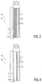
- the organic electroluminescent component according to the invention consists of a layer composite of a substrate layer 1 , a first, transparent electrode layer 2, one or more layers 3 , optionally with a p-conducting organic material 31 , with a luminescent material with one or more complexes of a rare earth metal ion with organic ones Ligands 32 and n-conducting organic material 33 and a second electrode 4 .
- a DC voltage is applied to the two electrodes.
- the first electrode is at positive potential (anode), the second at negative potential (cathode).
- the optoelectronic intermediate layer 3 usually consists of two separate layers for the p-conductive, ie hole-conducting material 31 and the n-conductive, ie electron-conductive material 33 .
- Either the p-type layer as in FIG. 2 or the n-type layer as in FIG. 1 or both as in FIG. 3 may also contain the electroluminescent material 32 with one or more complexes of a rare earth metal ion with organic ligands.
- the three materials are arranged in three separate layers - a hole conductor, Lunineszenz Anlagen, electron conductor.
- a plate made of a translucent material for example a glass plate, is always used as the substrate 1 .
- Anode 2 which must also be translucent, is applied as a thin film of a few 100 nm thickness. This is followed by the p- and then the n-type layer or the combined layer with p- and n-type material and the electroluminescent layer. The thicknesses of these layers are between 10 and 100 nm.
- the organic, electroluminescent component is completed by the cathode 4 .
- Metals, metal oxides or electrically conductive organic polymers with a high work function for electrons are suitable as the material for the transparent anode, from which holes are injected into the p-type layer.
- Examples are thin, transparent layers of indium-doped tin oxide (ITO), gold or polyaniline.
- molecularly doped organic polymers for the p-type layer, molecularly doped organic polymers, intrinsically conductive organic polymers, ie polymers with intrinsic conductivity or conductive organic monomers used.
- the prerequisite is that the lowest triplet state of these polymers or monomers is higher than that of the ligands of the rare earth complex: T1 p > T1 L , where T1 p is the lowest triplet state of the p-conducting organic polymer and T1 L is the lowest triplet -state of the ligand of the rare earth complex.
- An example of an intrinsically p-conducting, organic polymer is poly (N-vinylcarbazole) with T1 p of approximately 23,000 cm ⁇ 1.
- organic polymers traditionally serve as insulators or sheaths in the electrical and electronics industry. Recently, however, it has been possible to modify the conductivity of organic polymers by doping, that is to say by introducing precisely defined impurities, in such a way that they can also act as current conductors in electronic systems.
- doped organic polymers are e.g. B. arsenic pentafluoride or iodine-doped polyacetylene. These show metallic shine.
- MDP molecularly doped polymers
- MDP material with p-conducting properties is the solid solution made of the p-conductor N, N'-diphenyl-N, N'-bis (3-methylphenyl) -1,1'-biphenyl-4,4 ' diamine (TPD) as a doping in a matrix of polymethyl methacrylate or bisphenol A - polycarbonate.
- TPD p-conductor N, N'-diphenyl-N, N'-bis (3-methylphenyl) -1,1'-biphenyl-4,4 ' diamine
- poly (p-phenylene vinylene) and its derivatives or poly (methylphenylsilane) are also suitable.
- electroluminescent additives In layers with electroluminescent additives, however, their ability to make non-radiative transitions from the T 1 state interferes.
- a p-type organic monomers may be used for the present invention, for example, triphenylamine with T1 p of about 24 500cm ⁇ 1, Tritoluolamin with T1 p of about 24 or triphenyldiamine 000cm ⁇ 1 with T1 p of about 18 000cm ⁇ 1.
- These p-conductors have a triplet with T1 p of about 24 000 cm ⁇ 1.
- Intrinsically conductive organic monomers and polymers or polymers provided with molecular doping are also used for the layer with n-type conduction.
- Intrinsically conductive organic monomers that are suitable for the electron-transporting layer are 3,4,9,10-perylene-tetracarboxy-bis-benzimidazole, 2- (4-biphenylyl) -5- (tert-butylphenyl) -1,3 , 4-oxadiazole (butyl-PBD), 2- (4-biphenylyl) -5-phenyl-1,3,4-oxadiazole (PBD) with T1 n of approx. 20,500 cm ⁇ 1 or 2,5-diphenyl- 1,3,4-oxadiazole (PPD) with T1 n of about 23 500 cm ⁇ 1 and 8-hydroxyquinoline aluminum (Alq3).
- a polymethyl-methacrylate mixed with 8-hydroxyquinoline aluminum (Alq3) can be used as the n-conducting molecularly doped organic polymer.
- molecularly doped organic polymers that can be used according to the invention are composed, for example, of polymethyl methacrylate (PMMA), polystyrene or bisphenol A polycarbonate as a matrix with a doping of oxadiazoles such as 2- (4-biphenylyl) -5- (tert.
- PMMA polymethyl methacrylate
- polystyrene polystyrene
- bisphenol A polycarbonate as a matrix with a doping of oxadiazoles such as 2- (4-biphenylyl) -5- (tert.
- organic layer that is to say p-conducting and n-conducting organic polymers or monomers are arranged in a common, homogeneous layer
- molecularly doped polymers doped with p-conducting substances and with n-conducting substances.
- a combination of butyl-PBD in polymethyl methacrylate, polystyrene or bisphenol A - polycarbonate with other materials such as triphenylamine, triphenyldiamine or tritoluolamine is advantageous.
- the electroluminescent material contains one or more metallo-organic complexes of rare earth metals with organic oxygen, sulfur or nitrogen ligands.
- metallo-organic complexes are to be understood as meaning those complexes with the organic ligands mentioned in which the binding takes place via the heteroatoms.
- several rare earth metal complexes can also be used.
- Rare earth metal complexes that are not sublimable or not electrically conductive can also be used.
- the rare earth metal ion can be, for example, Eu2+, Eu3+, Tb3+, Tm3+, Dy3+, Sm3+, or Pr3+.
- Red fluorescence can be generated with europium and samarium complexes, green with the terbium complexes and blue with the thulium and dysprosium complexes.
- Rare earth metal complexes of the general composition SE [L1] 3 [L2] n are particularly suitable.
- SE is a trivalent rare earth metal cation
- L1 an anionic ligand, which can be monodentate or bidentate
- L2 a neutral ligand, which can be monodentate or bidentate.
- n is chosen so that all coordination sites of the rare earth are saturated, n can therefore take the values 0.1, 2, 3 and 4.
- L1 and L2 are always two different ligands. For Eu2+ the corresponding formula is Eu [L1] 2 [L2] n .
- the beta diketonates R1C (OH) CHCOR2 are particularly suitable as ligand L1.
- the radicals R1 and R2 can be F3C-, thenoyl C4H3S-, furanoyl C4H3O-, t-butyl and perfluoro-n-propyl C3F7-. If R1 and R2 are a CF3 radical, the beta diketonate hexafluoroacetyl acetonate (hfa) is obtained. If R1 and R2 are t-butyl, the beta-diketonate 2,2,6,6, -tetrametyl-3,5-heptanedione (thd) is obtained.
- R1 is a thenoyl radical and R2 is a CF3 radical
- the betadiketone thenoyltrifluoroacetylacetonate (ttfa) is obtained.
- R1 is a furanoyl radical and R2 is a CF3 radical
- the betadiketone furanolyltri-fluoroacerylacetonate (ftfa) is obtained.
- R1 is a t-butyl radical and R2 is a perfluoro-n-propyl radical
- Another beta-diketone that is suitable as a ligand is 3- (trifluoromethyl-hydroxymethylene) -l-camphor.
- the chelate complexes of the rare earth metals with ligands L 1, which are anions of aromatic carboxylic acids, such as benzoic acid, dipicolinic acid and picolinic acid, are particularly efficient.
- the ligands L2 are neutral ligands, which can be monodentate.
- the monodentate ligands can be pyridine and its derivatives, trialkyl, alkylphenyl and Triphenylphosphine oxides, dialkyl, alkylphenyl and diphenyl sulfoxides, alkyl, alkylphenyl and phenylamines and alkyl, alkylphenyl and phenyl phosphates.
- 2,2'-Bipyridine, 2,2 ', 6,2''terpyridine, 1,10 phenantroline and N, N, N', N'-tetramethylethylenediamine and their derivatives are suitable as multidentate ligands.
- the concentration of the rare earth metal complexes mentioned should not exceed 20 mol percent in order not to influence the transport properties of the conductive organic polymers, since the rare earth metal compounds mentioned are mostly insulators.
- ligands that have transport properties themselves.
- Such ligands are, for example, the carboxylic acids of diphenylamine or triphenylamine, such as diphenylamine-2-carboxylic acid or diphenylamine-2,2'-dicarboxylic acid, and also phenantroline, bipyridine and terpyridine. Complexes with these ligands are p-conductors.
- Metals with a low work function are used as the material for the cathode, since electrons have to be injected into the n-conducting layer from the cathode.
- Such metals are aluminum, magnesium and alloys of magnesium with silver or indium and calcium.
- the p- and n-type layers can be applied from solution, evaporated or polymerized in situ.
- the rare earth metal complexes can be sublimed, optionally together with the electrically conductive, organic monomers.
- This implementation begins when the voltage dropping across the functional intermediate layers has exceeded a certain threshold value. Then positive charge carriers, i.e. holes, are injected into the adjacent layer from the anode. Likewise, negative charge carriers, i.e. electrons, are injected from the cathode. At the transition between the p-type and the n-type layer, the recombination of holes and electrons takes place in a more or less narrow zone.
- E rec IP + -AP - ⁇ IA-2P
- I is the molecular ionization energy of the hole conductor
- A the molecular electron affinity of the electron conductor
- P+ and P ⁇ the polarization energies of the hole or the electron, which can be regarded as approximately the same.
- electrically neutral excitation states of the organic molecules are occupied if their excitation energy is equal to or less than the energy E rec released during the recombination. Normally, these states are the lowest excited singlet state S 1 and the lowest triplet state T 1, which is generally below S 1 for organic substances.
- the per se forbidden radiative transitions from the T 1 state to the ground state can only be observed as phosporescence at very low temperatures, for example at temperatures of the liquid nitrogen.
- the organic LEDs according to the prior art only use the singlet states and therefore have a low efficiency.
- the holes and electrons injected at the interface to the electrode are transported to the transition between p-type and n-type material.
- a strong space charge builds up here and the charge carriers recombine. If both the singlet state and the triplet state can be reached energetically, singlet and triplet excitons are generated in a ratio of 1: 3, which can then diffuse a certain distance through the material.
- the excitons release their energy and their spin to electroluminescent emitter molecules with lower energy levels. These excited molecules then either make a radiative transition to the ground state, emitting the desired quantum of luminescence, or it loses energy in one non-radiative transition, this excitation energy for the light output being lost.
- the overall efficiency of such an electroluminescent component is composed of ⁇ rec , the efficiency with which the injected charge carriers recombine, and ⁇ rad , the probability with which the excitons generated cause a radiative transition.
- the factor 0.25 takes into account the production frequency of the singlet excitons.
- the theoretical upper limit for the luminous efficacy in organic LEDs according to the prior art is therefore 25% if both the recombination and the radiative decay of the excitons take place with a probability of 1.
- the upper limit for LEDs according to the prior art is based on the fact that only singlet excitons can lead to permitted, radiative transitions.
- the triplet excitons are also used in that the possibility of energy transfer from the triplet states generated to the rare earth metal ion is created.
- the n- or p-conducting organic monomers or polymers are coupled with an electroluminescent material (emitter) which contains organometallic complexes of rare earth metals with low emitting states.
- an electroluminescent material which contains organometallic complexes of rare earth metals with low emitting states.
- the lowest emitting level of the rare earth metal ion is so far below the singlet and triplet states of the organic ligand that no thermally activated back transfer can take place.
- these rare earth metal complexes in addition to the normal singlet-singlet transitions, there is also Energy transfer allowed from the lowest triplet state of the organic ligand to the emitting level of the central rare earth metal ion.
- the prerequisite for this is the correct position of the triplet states of the different materials in relation to one another.
- the triplet state which is occupied by the recombination of electron and hole, must be above the triplet state of the ligand, since otherwise no energy transfer to the ligands is possible.
- the molecules of the rare earth complex act as traps for the triplet excitons, which are converted here into visible light.
- the quantum yield of these transitions can be very high, e.g. it is in Eu (ttfa) 3phen and Tb (benz) 3bipy2 at 50 to 70%.
- the first term refers to the portion derived from the singlet excitons.
- the second term indicates the proportion of the triplet excitons also used according to the invention.
- the electroluminescent component according to the invention is composed of two separate layers for the p- and the n-conducting polymer and the first excited triplet state of the substance of one layer is lower than that in the other layer, the triplet excitons preferentially diffuse into this layer with energetically lower triplet states.
- the singlet excitons Only the rare earth complexes incorporated into this layer can act as traps for the excitons and convert the electrical energy introduced into photons. According to the rare earth metal complex at least one of the organic layers must be buried, namely the one whose T1 state is lower.
- T1 p > T1 n The triplet excitons diffuse predominantly into the n-type layer, which must therefore contain the rare earth complexes as exciton trap.
- T1 n T1 L.
- T1 p ⁇ T1 n The triplet excitons diffuse predominantly into the p-type layer, which must therefore contain the rare earth complexes as an exciton trap.
- T1 p ⁇ T1 n The triplet excitons diffuse both in the p-type layer and in the n-type layer, these must therefore both contain the rare earth complexes as exciton trap.
- the exact position of the singlet, triplet or emitting states is obtained from the absorption spectra or the phosphorescence spectra of the respective compounds.
- the following mixture is spun onto an ITO-coated glass substrate at approx. 70 rpm: 1 ml PVK as a 2% solution in chlorobenzene 1 ml PBD as a 1% solution in chlorobenzene 0.1 ml Eu (ttfa) 3phen as a 1% solution in chlorobenzene After drying, the layer thickness is about 100 nm. Then electrodes made of calcium, 20 nm thick, are evaporated at 10 ⁇ 5 mbar, which are covered with aluminum, 200 nm thick. If the positive pole of a voltage source is connected to the ITO and the negative pole to the calcium, a bright red luminescence appears from 14 V, which consists exclusively of the characteristic lines of the Europium.
- the following mixture is spun onto an ITO-coated glass substrate at approx. 70 rpm: 1 ml PVK as a 2% solution in chlorobenzene 1 ml PBD as a 1% solution in chlorobenzene 0.1 ml Tb (benz) 3bipy2 in 1% solution in dimethylformamide After drying, the layer thickness is about 100 nm. Then 10 ⁇ 5 mbar electrodes made of calcium, 20 nm thick, are evaporated, which are covered with aluminum, 200 nm thick. If the positive pole of a voltage source is connected to the ITO and the negative pole to the calcium, a bright green luminescence appears from 14 V, which consists exclusively of the characteristic lines of terbium.
- the following layer sequence is vapor-deposited at about 10 mbar on a glass substrate coated with ITO: TPD, with a layer thickness of 50 nm as a hole conductor Eu (ttfa) 3phen as a luminescent substance Alq3; as an electron conductor, as well Calcium, 20 nm, and aluminum, 200 nm, as an electrode.
- the following layer sequence is vapor-deposited at about 10 mbar on a glass substrate coated with ITO: TPD in a layer thickness of 50 nm as a hole conductor, Eu (ttfa) 3phen mixed with bu-PBD in a ratio of 1:25, in a layer thickness of 50 nm as luminescent substance, Alq3 in a layer thickness of 35 nm as an electron conductor and calcium, 20 nm, and aluminum, 200 nm, as an electrode.
- the following layer sequence is vapor-deposited at about 10 mbar on a glass substrate coated with ITO: TPD in a layer thickness of 50 nm as a hole conductor, Eu (ftfa) 3phen in a layer thickness of 30 nm as luminescent substance, Alq3 in a layer thickness of 30 nm as an electron conductor and Calcium, 20 nm, and aluminum, 200 nm, as an electrode.
- the following layer sequence is vapor-deposited at about 10 mbar on a glass substrate coated with ITO: TPD 50 nm as a hole conductor Eu (thd) 3phen 30 nm as a luminescent substance Alq3 50 nm as an electron conductor. Calcium 20 nm Aluminum 200 nm.
- the layer thickness is about 100 nm.
- 10 ⁇ 5 mbar electrodes made of calcium, 20 nm thick, are evaporated, which are covered with aluminum, 200 nm thick. If the positive pole of a voltage source is connected to the ITO and the negative pole to the calcium, a very weak bluish luminescence appears from 18 V, which consists of a broad background and weak, overlaid characteristic lines of the terbium.
Landscapes
- Chemical & Material Sciences (AREA)
- Physics & Mathematics (AREA)
- Engineering & Computer Science (AREA)
- Inorganic Chemistry (AREA)
- Materials Engineering (AREA)
- Optics & Photonics (AREA)
- Sustainable Development (AREA)
- Spectroscopy & Molecular Physics (AREA)
- Life Sciences & Earth Sciences (AREA)
- Measurement Of Radiation (AREA)
- Electroluminescent Light Sources (AREA)
- Transforming Light Signals Into Electric Signals (AREA)
- Luminescent Compositions (AREA)
- Devices For Indicating Variable Information By Combining Individual Elements (AREA)
- Led Devices (AREA)
Applications Claiming Priority (4)
| Application Number | Priority Date | Filing Date | Title |
|---|---|---|---|
| DE4428450 | 1994-08-11 | ||
| DE4428450A DE4428450A1 (de) | 1994-08-11 | 1994-08-11 | Organisches, elektrolumineszentes Bauteil |
| EP94202340 | 1994-08-17 | ||
| EP94202340 | 1994-08-17 |
Publications (2)
| Publication Number | Publication Date |
|---|---|
| EP0697744A1 true EP0697744A1 (fr) | 1996-02-21 |
| EP0697744B1 EP0697744B1 (fr) | 2000-01-05 |
Family
ID=25939117
Family Applications (2)
| Application Number | Title | Priority Date | Filing Date |
|---|---|---|---|
| EP95925982A Expired - Lifetime EP0723701B1 (fr) | 1994-08-11 | 1995-08-08 | Intensificateur d'images a etat solide et appareil d'examen a rayons x comprenant un tel intensificateur |
| EP95202173A Expired - Lifetime EP0697744B1 (fr) | 1994-08-11 | 1995-08-10 | Dispositif électroluminescent organique |
Family Applications Before (1)
| Application Number | Title | Priority Date | Filing Date |
|---|---|---|---|
| EP95925982A Expired - Lifetime EP0723701B1 (fr) | 1994-08-11 | 1995-08-08 | Intensificateur d'images a etat solide et appareil d'examen a rayons x comprenant un tel intensificateur |
Country Status (5)
| Country | Link |
|---|---|
| US (2) | US5756224A (fr) |
| EP (2) | EP0723701B1 (fr) |
| JP (2) | JP2002516629A (fr) |
| DE (2) | DE69514495T2 (fr) |
| WO (1) | WO1996005607A1 (fr) |
Cited By (9)
| Publication number | Priority date | Publication date | Assignee | Title |
|---|---|---|---|---|
| EP1214746A2 (fr) * | 2000-05-22 | 2002-06-19 | Showa Denko K.K. | Dispositif organique electroluminescent et matiere luminescente |
| US6723454B2 (en) | 1999-04-23 | 2004-04-20 | Koninklijke Philips Electronics N.V. | Luminescent device |
| US7103124B1 (en) | 1999-12-30 | 2006-09-05 | Telefonaktiebolaget Lm Ericsson (Publ) | Synchronization of nodes |
| EP2262030A2 (fr) * | 1997-10-09 | 2010-12-15 | The Trustees Of Princeton University | Dispositif organique émetteur de lumière |
| EP2276084A1 (fr) * | 2001-03-14 | 2011-01-19 | The Trustees of Princeton University | Matériaux et dispositifs pour diodes luminescentes organiques basées sur phosphorescence bleu |
| EP1297060B2 (fr) † | 2000-06-12 | 2012-04-04 | Sumitomo Chemical Company Limited | Dispositifs et materiaux electroluminescents a matrice polymere |
| US8206838B2 (en) | 2000-06-12 | 2012-06-26 | Sumitomo Chemical Co., Ltd. | Polymer matrix electroluminescent materials and devices |
| US8623524B2 (en) | 2002-10-09 | 2014-01-07 | Idemitsu Kosan Co., Ltd. | Organic electroluminescent device |
| EP1181842B1 (fr) | 1999-03-23 | 2016-05-25 | University Of Southern California | Complexes metalliques cyclometallises en tant que dopants phosphorescents dans des dispositifs electroluminescents organiques |
Families Citing this family (130)
| Publication number | Priority date | Publication date | Assignee | Title |
|---|---|---|---|---|
| KR100332186B1 (ko) * | 1995-11-28 | 2002-05-09 | 포만 제프리 엘 | 유기전자발광소자를향상시키기위하여사용된유기/무기합금 |
| US6623870B1 (en) * | 1996-08-02 | 2003-09-23 | The Ohio State University | Electroluminescence in light emitting polymers featuring deaggregated polymers |
| ATE323749T1 (de) * | 1997-03-11 | 2006-05-15 | Univ Ohio State Res Found | Bipolare/ac lichtemittierende vorrichtungen mit variabler farbe |
| GB9712483D0 (en) | 1997-06-17 | 1997-08-20 | Kathirgamanathan Poopathy | Fabrication of light emitting devices from chelates of transition metals, lanthanides and actinides |
| WO1998059260A2 (fr) * | 1997-06-24 | 1998-12-30 | Fraunhofer-Gesellschaft zur Förderung der angewandten Forschung e.V. | Camera de radiographie a fibre optique |
| US6303238B1 (en) * | 1997-12-01 | 2001-10-16 | The Trustees Of Princeton University | OLEDs doped with phosphorescent compounds |
| DE19756361A1 (de) * | 1997-12-18 | 1999-06-24 | Philips Patentverwaltung | Organische lichtemittierende Diode mit Terbiumkomplex |
| GB9805476D0 (en) | 1998-03-13 | 1998-05-13 | Cambridge Display Tech Ltd | Electroluminescent devices |
| JP3825564B2 (ja) * | 1998-05-25 | 2006-09-27 | 三洋電機株式会社 | 有機エレクトロルミネッセンス素子 |
| US6830828B2 (en) | 1998-09-14 | 2004-12-14 | The Trustees Of Princeton University | Organometallic complexes as phosphorescent emitters in organic LEDs |
| EP1051453A1 (fr) * | 1998-11-26 | 2000-11-15 | Koninklijke Philips Electronics N.V. | Lampe a decharge |
| US7001536B2 (en) * | 1999-03-23 | 2006-02-21 | The Trustees Of Princeton University | Organometallic complexes as phosphorescent emitters in organic LEDs |
| CN101312235B (zh) * | 1999-05-13 | 2010-06-09 | 普林斯顿大学理事会 | 基于电致磷光的极高效有机发光器件 |
| JP4138167B2 (ja) * | 1999-07-13 | 2008-08-20 | ローム株式会社 | 有機エレクトロルミネッセンス表示装置用基板、表示装置およびその製造方法 |
| US6593690B1 (en) | 1999-09-03 | 2003-07-15 | 3M Innovative Properties Company | Large area organic electronic devices having conducting polymer buffer layers and methods of making same |
| US7768210B2 (en) * | 1999-12-22 | 2010-08-03 | General Electric Company | Hybrid electroluminescent devices |
| JP2011084746A (ja) * | 1999-12-27 | 2011-04-28 | Fujifilm Corp | オルトメタル化イリジウム錯体からなる発光素子材料、発光素子及び新規イリジウム錯体 |
| US6821645B2 (en) * | 1999-12-27 | 2004-11-23 | Fuji Photo Film Co., Ltd. | Light-emitting material comprising orthometalated iridium complex, light-emitting device, high efficiency red light-emitting device, and novel iridium complex |
| TW536836B (en) * | 2000-05-22 | 2003-06-11 | Semiconductor Energy Lab | Light emitting device and electrical appliance |
| US7339317B2 (en) * | 2000-06-05 | 2008-03-04 | Semiconductor Energy Laboratory Co., Ltd. | Light-emitting device having triplet and singlet compound in light-emitting layers |
| JP2002043056A (ja) | 2000-07-19 | 2002-02-08 | Canon Inc | 発光素子 |
| US6905784B2 (en) | 2000-08-22 | 2005-06-14 | Semiconductor Energy Laboratory Co., Ltd. | Light emitting device |
| US6864628B2 (en) | 2000-08-28 | 2005-03-08 | Semiconductor Energy Laboratory Co., Ltd. | Light emitting device comprising light-emitting layer having triplet compound and light-emitting layer having singlet compound |
| JP4154139B2 (ja) * | 2000-09-26 | 2008-09-24 | キヤノン株式会社 | 発光素子 |
| JP4154138B2 (ja) | 2000-09-26 | 2008-09-24 | キヤノン株式会社 | 発光素子、表示装置及び金属配位化合物 |
| JP4154140B2 (ja) | 2000-09-26 | 2008-09-24 | キヤノン株式会社 | 金属配位化合物 |
| JP4086499B2 (ja) | 2000-11-29 | 2008-05-14 | キヤノン株式会社 | 金属配位化合物、発光素子及び表示装置 |
| JP4086498B2 (ja) | 2000-11-29 | 2008-05-14 | キヤノン株式会社 | 金属配位化合物、発光素子及び表示装置 |
| US7221088B2 (en) * | 2000-11-29 | 2007-05-22 | The United States Of America As Represented By The Secretary Of The Navy | Universal host for RG or RGB emission in organic light emitting devices |
| JP4154145B2 (ja) * | 2000-12-01 | 2008-09-24 | キヤノン株式会社 | 金属配位化合物、発光素子及び表示装置 |
| JP2002184581A (ja) * | 2000-12-13 | 2002-06-28 | Sanyo Electric Co Ltd | 有機発光素子 |
| SG2009086778A (en) | 2000-12-28 | 2016-11-29 | Semiconductor Energy Lab Co Ltd | Luminescent device |
| DE60134618D1 (de) * | 2000-12-28 | 2008-08-14 | Toshiba Kk | Organische elektrolumineszente Vorrichtung und Anzeigevorrichtung |
| SG118110A1 (en) * | 2001-02-01 | 2006-01-27 | Semiconductor Energy Lab | Organic light emitting element and display device using the element |
| DE10109027A1 (de) * | 2001-02-24 | 2002-09-05 | Covion Organic Semiconductors | Rhodium- und Iridium-Komplexe |
| KR100898304B1 (ko) * | 2001-03-02 | 2009-05-19 | 더 트러스티즈 오브 프린스턴 유니버시티 | 이중 도우프층, 인광 유기 발광 디바이스 |
| JP4438042B2 (ja) | 2001-03-08 | 2010-03-24 | キヤノン株式会社 | 金属配位化合物、電界発光素子及び表示装置 |
| US7009338B2 (en) * | 2001-05-16 | 2006-03-07 | The University Of Southern California | High efficiency multi-color electro-phosphorescent OLEDs |
| US7199515B2 (en) * | 2001-06-01 | 2007-04-03 | Semiconductor Energy Laboratory Co., Ltd. | Organic light emitting element and light emitting device using the element |
| US6875523B2 (en) * | 2001-07-05 | 2005-04-05 | E. I. Du Pont De Nemours And Company | Photoactive lanthanide complexes with phosphine oxides, phosphine oxide-sulfides, pyridine N-oxides, and phosphine oxide-pyridine N-oxides, and devices made with such complexes |
| KR20040018467A (ko) * | 2001-07-18 | 2004-03-03 | 이 아이 듀폰 디 네모아 앤드 캄파니 | 이민 리간드와의 발광 란탄족 착물 및 이러한 착물을사용하여 제조된 장치 |
| DE10137012B4 (de) * | 2001-07-31 | 2011-03-17 | Siemens Ag | Röntgendiagnostikeinrichtung mit einem flächenhaften Festkörper-Röntgenbildwandler |
| WO2003022908A1 (fr) * | 2001-09-04 | 2003-03-20 | Canon Kabushiki Kaisha | Composes de poids moleculaire eleve et dispositifs luminescents organiques |
| US6734457B2 (en) | 2001-11-27 | 2004-05-11 | Semiconductor Energy Laboratory Co., Ltd. | Light emitting device |
| SG142163A1 (en) | 2001-12-05 | 2008-05-28 | Semiconductor Energy Lab | Organic semiconductor element |
| JP2003323988A (ja) * | 2002-02-28 | 2003-11-14 | Semiconductor Energy Lab Co Ltd | 発光装置及びそれを用いた電気器具 |
| JP2003323977A (ja) * | 2002-02-28 | 2003-11-14 | Semiconductor Energy Lab Co Ltd | 発光装置の駆動方法 |
| US6809481B2 (en) * | 2002-02-28 | 2004-10-26 | Semiconductor Energy Laboratory Co., Ltd. | Light emitting device and electric device using the same |
| JP4298517B2 (ja) * | 2002-03-08 | 2009-07-22 | キヤノン株式会社 | 有機発光素子 |
| US20030189193A1 (en) * | 2002-03-26 | 2003-10-09 | Mininni Robert M. | Fluorinated and halogenated phosphinic acids and their active metal derivatives |
| US20030193796A1 (en) * | 2002-04-15 | 2003-10-16 | Heeks Stephen K. | Light-emitting devices |
| US7135423B2 (en) | 2002-05-09 | 2006-11-14 | Varian Semiconductor Equipment Associates, Inc | Methods for forming low resistivity, ultrashallow junctions with low damage |
| JP3902981B2 (ja) * | 2002-06-04 | 2007-04-11 | キヤノン株式会社 | 有機発光素子及び表示装置 |
| US6923356B2 (en) | 2002-08-22 | 2005-08-02 | Michael Reynolds | Method and apparatus for retaining bags |
| USD495140S1 (en) | 2002-08-22 | 2004-08-31 | Michael Reynolds | Apparatus for retaining bags |
| JP4343511B2 (ja) * | 2002-10-08 | 2009-10-14 | キヤノン株式会社 | 多色発光素子 |
| JP4683924B2 (ja) * | 2002-12-19 | 2011-05-18 | 株式会社半導体エネルギー研究所 | 発光材料、電界発光素子、及び発光装置 |
| KR101035818B1 (ko) * | 2003-01-24 | 2011-05-20 | 이데미쓰 고산 가부시키가이샤 | 유기 전기발광 소자 |
| US7196334B2 (en) * | 2003-04-24 | 2007-03-27 | Koninklijke Philips Electronics N.V. | X-ray detector element |
| JP2004352928A (ja) * | 2003-05-30 | 2004-12-16 | Mitsubishi Chemicals Corp | 発光装置及び照明装置 |
| CN101667626B (zh) * | 2003-06-02 | 2012-11-28 | 富士胶片株式会社 | 有机电致发光装置和金属络合化合物 |
| US7569692B2 (en) | 2003-06-02 | 2009-08-04 | Fujifilm Corporation | Organic electroluminescent devices and metal complex compounds |
| US7955716B2 (en) | 2003-06-09 | 2011-06-07 | Hitachi Chemical Co., Ltd. | Metal coordination compound, polymer composition, and organic electroluminescent device employing same |
| US8008418B2 (en) | 2003-06-18 | 2011-08-30 | Hitachi Chemical Co., Ltd. | High-molecular copolymer containing metal coordination compound and organic electroluminescence element using the same |
| JP2005071986A (ja) * | 2003-08-04 | 2005-03-17 | Fuji Photo Film Co Ltd | 有機電界発光素子 |
| US7935432B2 (en) * | 2003-09-19 | 2011-05-03 | Fujifilm Corporation | Organic electroluminescent device |
| US7046763B2 (en) * | 2003-12-23 | 2006-05-16 | General Electric Company | Field and factory testable imaging detector |
| US20050244672A1 (en) * | 2004-04-30 | 2005-11-03 | Chi-Ming Che | Organic light-emitting devices |
| US20060042685A1 (en) * | 2004-08-25 | 2006-03-02 | Ying Wang | Electronic devices having a charge transport layer that has defined triplet energy level |
| ITMN20040024A1 (it) * | 2004-09-24 | 2004-12-24 | Pe Srl | Macchina etichettatrice per etichette destinate a termoretrazione |
| JP4712372B2 (ja) | 2004-12-16 | 2011-06-29 | 株式会社半導体エネルギー研究所 | 発光装置 |
| US9070884B2 (en) | 2005-04-13 | 2015-06-30 | Universal Display Corporation | Hybrid OLED having phosphorescent and fluorescent emitters |
| US7474048B2 (en) * | 2005-06-01 | 2009-01-06 | The Trustees Of Princeton University | Fluorescent filtered electrophosphorescence |
| WO2006130883A2 (fr) * | 2005-06-01 | 2006-12-07 | The Trustees Of Princeton University | Electrophosphorescence a filtre fluorescent |
| DE102005046450A1 (de) * | 2005-09-28 | 2007-04-05 | Osram Opto Semiconductors Gmbh | Optoelektronischer Halbleiterchip, Verfahren zu dessen Herstellung und optoelektronisches Bauteil |
| JP2007194194A (ja) * | 2005-12-22 | 2007-08-02 | Matsushita Electric Ind Co Ltd | エレクトロルミネッセンス素子およびこれを用いた表示装置、露光装置、照明装置 |
| US7846639B2 (en) | 2006-06-30 | 2010-12-07 | E. I. Du Pont De Nemours And Company | Imaging element having a photoluminescent tag and process of using the imaging element to form a recording element |
| FR2906393B1 (fr) * | 2006-09-21 | 2008-12-19 | Inst Nat Sciences Appliq | Procede de marquage d'un materiau comprenant au moins une matrice minerale et materiau correspondant |
| KR101435503B1 (ko) | 2006-11-30 | 2014-08-29 | 가부시키가이샤 한도오따이 에네루기 켄큐쇼 | 발광 장치 |
| KR100989817B1 (ko) * | 2007-07-24 | 2010-10-29 | 다우어드밴스드디스플레이머티리얼 유한회사 | 신규한 적색 인광 화합물 및 이를 발광재료로서 채용하고있는 유기 전계 발광 소자 |
| KR100850886B1 (ko) * | 2007-09-07 | 2008-08-07 | (주)그라쎌 | 전기발광용 유기금속 화합물 및 이를 발광재료로 채용하고있는 표시소자 |
| KR100923655B1 (ko) * | 2007-11-02 | 2009-10-28 | (주)그라쎌 | 신규한 적색 인광 화합물 및 이를 발광재료로서 채용하고있는 유기발광소자 |
| KR100933229B1 (ko) * | 2007-11-12 | 2009-12-22 | 다우어드밴스드디스플레이머티리얼 유한회사 | 신규한 적색 인광 화합물 및 이를 발광재료로서 채용하고있는 유기발광소자 |
| KR100933226B1 (ko) * | 2007-11-20 | 2009-12-22 | 다우어드밴스드디스플레이머티리얼 유한회사 | 신규한 적색 인광 화합물 및 이를 발광재료로서 채용하고있는 유기발광소자 |
| KR100910153B1 (ko) * | 2007-11-20 | 2009-07-30 | (주)그라쎌 | 신규한 적색 인광 화합물 및 이를 발광재료로서 채용하고있는 유기발광소자 |
| KR100910151B1 (ko) * | 2007-11-22 | 2009-07-30 | (주)그라쎌 | 신규한 유기 발광 화합물 및 이를 발광재료로 채용하고있는 전기발광소자 |
| KR100933225B1 (ko) * | 2007-11-27 | 2009-12-22 | 다우어드밴스드디스플레이머티리얼 유한회사 | 신규한 인광 화합물 및 이를 발광재료로서 채용하고 있는유기발광소자 |
| US8118447B2 (en) | 2007-12-20 | 2012-02-21 | Altair Engineering, Inc. | LED lighting apparatus with swivel connection |
| US7712918B2 (en) | 2007-12-21 | 2010-05-11 | Altair Engineering , Inc. | Light distribution using a light emitting diode assembly |
| KR100970713B1 (ko) * | 2007-12-31 | 2010-07-16 | 다우어드밴스드디스플레이머티리얼 유한회사 | 유기발광화합물을 발광재료로서 채용하고 있는 전기 발광소자 |
| KR100966886B1 (ko) * | 2008-01-29 | 2010-06-30 | 다우어드밴스드디스플레이머티리얼 유한회사 | 신규한 유기 발광 화합물 및 이를 발광재료로서 채용하고있는 유기발광소자 |
| KR100966885B1 (ko) * | 2008-02-29 | 2010-06-30 | 다우어드밴스드디스플레이머티리얼 유한회사 | 신규한 유기 발광 화합물 및 이를 발광재료로서 채용하고있는 유기 전계 발광 소자 |
| KR100946409B1 (ko) * | 2008-03-19 | 2010-03-09 | 다우어드밴스드디스플레이머티리얼 유한회사 | 신규한 유기 발광 화합물 및 이를 발광재료로서 채용하고있는 유기 전계 발광 소자 |
| US8664523B2 (en) * | 2008-05-08 | 2014-03-04 | Georgia Tech Research Corporation | Fiber optic solar nanogenerator cells |
| US8360599B2 (en) | 2008-05-23 | 2013-01-29 | Ilumisys, Inc. | Electric shock resistant L.E.D. based light |
| US7976196B2 (en) | 2008-07-09 | 2011-07-12 | Altair Engineering, Inc. | Method of forming LED-based light and resulting LED-based light |
| US7946729B2 (en) | 2008-07-31 | 2011-05-24 | Altair Engineering, Inc. | Fluorescent tube replacement having longitudinally oriented LEDs |
| US8674626B2 (en) | 2008-09-02 | 2014-03-18 | Ilumisys, Inc. | LED lamp failure alerting system |
| US8256924B2 (en) | 2008-09-15 | 2012-09-04 | Ilumisys, Inc. | LED-based light having rapidly oscillating LEDs |
| US8653984B2 (en) | 2008-10-24 | 2014-02-18 | Ilumisys, Inc. | Integration of LED lighting control with emergency notification systems |
| US7938562B2 (en) | 2008-10-24 | 2011-05-10 | Altair Engineering, Inc. | Lighting including integral communication apparatus |
| US8214084B2 (en) | 2008-10-24 | 2012-07-03 | Ilumisys, Inc. | Integration of LED lighting with building controls |
| US8444292B2 (en) | 2008-10-24 | 2013-05-21 | Ilumisys, Inc. | End cap substitute for LED-based tube replacement light |
| US8901823B2 (en) | 2008-10-24 | 2014-12-02 | Ilumisys, Inc. | Light and light sensor |
| US8324817B2 (en) | 2008-10-24 | 2012-12-04 | Ilumisys, Inc. | Light and light sensor |
| KR101520029B1 (ko) * | 2008-12-31 | 2015-05-15 | 삼성전자주식회사 | 고정세화 패턴을 갖는 광 변조기 |
| US8556452B2 (en) | 2009-01-15 | 2013-10-15 | Ilumisys, Inc. | LED lens |
| US8362710B2 (en) | 2009-01-21 | 2013-01-29 | Ilumisys, Inc. | Direct AC-to-DC converter for passive component minimization and universal operation of LED arrays |
| US8664880B2 (en) | 2009-01-21 | 2014-03-04 | Ilumisys, Inc. | Ballast/line detection circuit for fluorescent replacement lamps |
| TWI468493B (zh) | 2009-02-27 | 2015-01-11 | Nippon Steel & Sumikin Chem Co | A polymer luminescent material, a method for manufacturing the same, and an organic electroluminescent device |
| JP5624784B2 (ja) * | 2009-03-31 | 2014-11-12 | 株式会社半導体エネルギー研究所 | ヘテロ芳香環を有する誘導体、ヘテロ芳香環を有する誘導体を用いた発光素子、発光装置、照明装置、電子機器 |
| US8330381B2 (en) | 2009-05-14 | 2012-12-11 | Ilumisys, Inc. | Electronic circuit for DC conversion of fluorescent lighting ballast |
| US8299695B2 (en) | 2009-06-02 | 2012-10-30 | Ilumisys, Inc. | Screw-in LED bulb comprising a base having outwardly projecting nodes |
| CA2765200A1 (fr) | 2009-06-23 | 2011-01-13 | Altair Engineering, Inc. | Dispositif d'eclairage comprenant des del et un systeme de commande d'alimentation a decoupage |
| WO2011119958A1 (fr) | 2010-03-26 | 2011-09-29 | Altair Engineering, Inc. | Lampe à del interne-externe |
| EP2553320A4 (fr) | 2010-03-26 | 2014-06-18 | Ilumisys Inc | Lampe à del comprenant un générateur thermoélectrique |
| CA2794512A1 (fr) | 2010-03-26 | 2011-09-29 | Ilumisys, Inc. | Tube de lampe a del avec repartition lumineuse laterale double |
| US8454193B2 (en) | 2010-07-08 | 2013-06-04 | Ilumisys, Inc. | Independent modules for LED fluorescent light tube replacement |
| EP2593714A2 (fr) | 2010-07-12 | 2013-05-22 | iLumisys, Inc. | Support de carte de circuit imprimé pour un tube de lampe à diodes électroluminescentes |
| WO2012058556A2 (fr) | 2010-10-29 | 2012-05-03 | Altair Engineering, Inc. | Mécanismes pour réduire le risque d'électrocution pendant l'installation d'un tube fluorescent |
| US8870415B2 (en) | 2010-12-09 | 2014-10-28 | Ilumisys, Inc. | LED fluorescent tube replacement light with reduced shock hazard |
| US9072171B2 (en) | 2011-08-24 | 2015-06-30 | Ilumisys, Inc. | Circuit board mount for LED light |
| US9184518B2 (en) | 2012-03-02 | 2015-11-10 | Ilumisys, Inc. | Electrical connector header for an LED-based light |
| US9163794B2 (en) | 2012-07-06 | 2015-10-20 | Ilumisys, Inc. | Power supply assembly for LED-based light tube |
| US9271367B2 (en) | 2012-07-09 | 2016-02-23 | Ilumisys, Inc. | System and method for controlling operation of an LED-based light |
| US9285084B2 (en) | 2013-03-14 | 2016-03-15 | Ilumisys, Inc. | Diffusers for LED-based lights |
| US9267650B2 (en) | 2013-10-09 | 2016-02-23 | Ilumisys, Inc. | Lens for an LED-based light |
| JP2017504166A (ja) | 2014-01-22 | 2017-02-02 | イルミシス, インコーポレイテッドiLumisys, Inc. | アドレス指定されたledを有するledベース電灯 |
| US9510400B2 (en) | 2014-05-13 | 2016-11-29 | Ilumisys, Inc. | User input systems for an LED-based light |
| US10161568B2 (en) | 2015-06-01 | 2018-12-25 | Ilumisys, Inc. | LED-based light with canted outer walls |
Citations (2)
| Publication number | Priority date | Publication date | Assignee | Title |
|---|---|---|---|---|
| JPH03289089A (ja) * | 1990-04-03 | 1991-12-19 | Mitsui Toatsu Chem Inc | 有機発光素子 |
| US5128587A (en) | 1989-12-26 | 1992-07-07 | Moltech Corporation | Electroluminescent device based on organometallic membrane |
Family Cites Families (14)
| Publication number | Priority date | Publication date | Assignee | Title |
|---|---|---|---|---|
| US310408A (en) * | 1885-01-06 | Gideon gibson | ||
| US2301967A (en) * | 1941-09-16 | 1942-11-17 | Paul W Nosker | Acceleration producing machine |
| US2505601A (en) * | 1945-07-31 | 1950-04-25 | Glenn L Martin Co | Apparatus for calibrating vibration equipment |
| US2971364A (en) * | 1956-02-08 | 1961-02-14 | Ernest K Gatcombe | Apparatus and methods for calibrating motion transducers |
| US2974536A (en) * | 1959-03-05 | 1961-03-14 | Alexander J Yorgiadis | Adjustable-while-running oscillator |
| US3277697A (en) * | 1965-07-06 | 1966-10-11 | Bruno A Wittkuhns | Vibration testing machine with continuously adjustable amplitude and frequency |
| US3543032A (en) * | 1968-05-06 | 1970-11-24 | Xerox Corp | Device and process for amplifying and storing an image |
| GB1331430A (en) * | 1969-12-11 | 1973-09-26 | Mullard Ltd | Photo-conductive image intensifiers |
| US3710181A (en) * | 1970-09-22 | 1973-01-09 | Matsushita Electric Industrial Co Ltd | Solid-state image intensifier |
| IT948418B (it) * | 1972-02-02 | 1973-05-30 | Minnesota Mining & Mfg | Sistema formato dalla combinazione di un intensificatore di immagine a stato solido e una pellicola o lastra radiografica agli alogenuri d argento |
| DE3207085A1 (de) * | 1982-02-26 | 1983-09-08 | Siemens AG, 1000 Berlin und 8000 München | Roentgendiagnostikeinrichtung mit einer bildverstaerker-fernsehkette |
| US4495433A (en) * | 1983-11-22 | 1985-01-22 | The United States Of America As Represented By The Secretary Of The Navy | Dual capability piezoelectric shaker |
| GB8909011D0 (en) * | 1989-04-20 | 1989-06-07 | Friend Richard H | Electroluminescent devices |
| US5005439A (en) * | 1989-07-14 | 1991-04-09 | Barry Wright Corporation | Inertia force generating device |
-
1995
- 1995-08-08 EP EP95925982A patent/EP0723701B1/fr not_active Expired - Lifetime
- 1995-08-08 DE DE69514495T patent/DE69514495T2/de not_active Expired - Fee Related
- 1995-08-08 WO PCT/IB1995/000620 patent/WO1996005607A1/fr not_active Ceased
- 1995-08-08 JP JP50716396A patent/JP2002516629A/ja not_active Ceased
- 1995-08-10 US US08/513,373 patent/US5756224A/en not_active Expired - Fee Related
- 1995-08-10 US US08/513,330 patent/US5698858A/en not_active Expired - Fee Related
- 1995-08-10 DE DE59507560T patent/DE59507560D1/de not_active Expired - Fee Related
- 1995-08-10 EP EP95202173A patent/EP0697744B1/fr not_active Expired - Lifetime
- 1995-08-11 JP JP20596695A patent/JPH08319482A/ja active Pending
Patent Citations (2)
| Publication number | Priority date | Publication date | Assignee | Title |
|---|---|---|---|---|
| US5128587A (en) | 1989-12-26 | 1992-07-07 | Moltech Corporation | Electroluminescent device based on organometallic membrane |
| JPH03289089A (ja) * | 1990-04-03 | 1991-12-19 | Mitsui Toatsu Chem Inc | 有機発光素子 |
Non-Patent Citations (7)
| Title |
|---|
| J. APPL. PHYS., vol. 72, 1992, pages 1957 |
| KIDO J ET AL: "Bright red light-emitting organic electroluminescent devices having a europium complex as an emitter", APPLIED PHYSICS LETTERS, 24 OCT. 1994, USA, vol. 65, no. 17, ISSN 0003-6951, pages 2124 - 2126 * |
| KIDO J ET AL: "Organic electroluminescent devices using lanthanide complexes", INTERNATIONAL CONFERENCE, RARE EARTHS '92, KYOTO, JAPAN, 1-5 JUNE 1992, vol. 192, no. 1-2, ISSN 0925-8388, JOURNAL OF ALLOYS AND COMPOUNDS, 23 FEB. 1993, SWITZERLAND, pages 30 - 33, XP024176323, DOI: doi:10.1016/0925-8388(93)90176-N * |
| NATURE, vol. 365, pages 628 |
| P.M. BAUSENBERGER, D.S. WEISS: "Organic Photoreceptors for Imaging SYstems", 1993, MARCEL DEKKER, NEW YORK |
| PATENT ABSTRACTS OF JAPAN vol. 016, no. 120 (E - 1182) 26 March 1992 (1992-03-26) * |
| TAKADA N ET AL: "Strongly-directed emission from microcavity structure in electroluminescent diodes with europium complex as an emitter", INTERNATIONAL CONFERENCE ON SCIENCE AND TECHNOLOGY OF SYNTHETIC METALS (ICSM '94), SEOUL, SOUTH KOREA, 24-29 JULY 1994, vol. 71, no. 1-3, ISSN 0379-6779, SYNTHETIC METALS, 1 APRIL 1995, SWITZERLAND, pages 2099 - 2100 * |
Cited By (13)
| Publication number | Priority date | Publication date | Assignee | Title |
|---|---|---|---|---|
| EP2262030A2 (fr) * | 1997-10-09 | 2010-12-15 | The Trustees Of Princeton University | Dispositif organique émetteur de lumière |
| EP3076759A1 (fr) | 1999-03-23 | 2016-10-05 | The University Of Southern California | Complexes métalliques cyclométallisés en tant que dopants phosphorescents dans des diodes électroluminescentes organiques |
| EP1181842B1 (fr) | 1999-03-23 | 2016-05-25 | University Of Southern California | Complexes metalliques cyclometallises en tant que dopants phosphorescents dans des dispositifs electroluminescents organiques |
| US6723454B2 (en) | 1999-04-23 | 2004-04-20 | Koninklijke Philips Electronics N.V. | Luminescent device |
| US7103124B1 (en) | 1999-12-30 | 2006-09-05 | Telefonaktiebolaget Lm Ericsson (Publ) | Synchronization of nodes |
| EP1214746A2 (fr) * | 2000-05-22 | 2002-06-19 | Showa Denko K.K. | Dispositif organique electroluminescent et matiere luminescente |
| US8206838B2 (en) | 2000-06-12 | 2012-06-26 | Sumitomo Chemical Co., Ltd. | Polymer matrix electroluminescent materials and devices |
| US8308978B2 (en) | 2000-06-12 | 2012-11-13 | Sumitomo Chemical Co., Ltd. | Polymer matrix electroluminescent materials and devices |
| EP2272906A3 (fr) * | 2000-06-12 | 2014-10-22 | Sumitomo Chemical Company Limited | Compositions pour matériau électroluminescent et leurs dispositifs |
| EP2272904A3 (fr) * | 2000-06-12 | 2014-10-22 | Sumitomo Chemical Company Limited | Compositions pour matériau électroluminescent et leurs dispositifs |
| EP1297060B2 (fr) † | 2000-06-12 | 2012-04-04 | Sumitomo Chemical Company Limited | Dispositifs et materiaux electroluminescents a matrice polymere |
| EP2276084A1 (fr) * | 2001-03-14 | 2011-01-19 | The Trustees of Princeton University | Matériaux et dispositifs pour diodes luminescentes organiques basées sur phosphorescence bleu |
| US8623524B2 (en) | 2002-10-09 | 2014-01-07 | Idemitsu Kosan Co., Ltd. | Organic electroluminescent device |
Also Published As
| Publication number | Publication date |
|---|---|
| DE69514495T2 (de) | 2000-08-10 |
| EP0697744B1 (fr) | 2000-01-05 |
| JP2002516629A (ja) | 2002-06-04 |
| DE69514495D1 (de) | 2000-02-17 |
| DE59507560D1 (de) | 2000-02-10 |
| EP0723701A1 (fr) | 1996-07-31 |
| JPH08319482A (ja) | 1996-12-03 |
| EP0723701B1 (fr) | 2000-01-12 |
| US5698858A (en) | 1997-12-16 |
| US5756224A (en) | 1998-05-26 |
| WO1996005607A1 (fr) | 1996-02-22 |
Similar Documents
| Publication | Publication Date | Title |
|---|---|---|
| EP0697744B1 (fr) | Dispositif électroluminescent organique | |
| EP0924281B1 (fr) | Dispositif organique émettant de la lumière avec un complexe de terbium | |
| DE69526614T2 (de) | Lichtemittierende Vorrichtungen die Organometallische Komplexe enthalten. | |
| DE69815576T2 (de) | Organisches elektrolumineszentes Bauteil | |
| DE69724107T2 (de) | Polyfluorene als materialien für photolumineszenz und elektrolumineszenz | |
| DE69306116T2 (de) | Elektrolumineszente vorrichtungen | |
| DE69027760T2 (de) | Organisches elektrolumineszentes element | |
| DE60130762T3 (de) | Elektrolumineszierende materialien und gegenstände aus einer polymermatrix | |
| EP0817281B1 (fr) | Dispositif organique électroluminescent ayant une couche inorganique transporteuse d'électrons | |
| DE112009000181B4 (de) | Verfahren zur Herstellung Weißlicht emittierenden Materials | |
| DE69306115T2 (de) | Elektrolumineszierende vorrichtungen und verfahren zu ihrer herstellung | |
| DE102013017361B4 (de) | Organisches Licht emittierendes Bauelement und Verfahren zur Herstellung eines organischen Licht ermittierenden Bauelements | |
| EP0831676B1 (fr) | Elément électroluminescent organique avec exciplex | |
| DE112011102874B4 (de) | Vernetzte Ladungstransportschicht, welche eine Zusatzverbindung enthält | |
| DE10224021A1 (de) | Phosphoreszentes lichtemittierendes Bauelement mit organischen Schichten | |
| DE10232238A1 (de) | Elektrolumineszierende Vorrichtung aus zweidimensionalem Array | |
| EP2126996B1 (fr) | Composant organique électrique à substance dopante rhénium et procédé pour le produire | |
| EP2652811B1 (fr) | Composant optoélectronique et utilisation d'un complexe de cuivre dans une succession de couches de génération de charge | |
| WO2012136422A1 (fr) | Composant optoélectronique et utilisation d'un complexe de cuivre comme agent dopant pour doper une couche | |
| DE4428450A1 (de) | Organisches, elektrolumineszentes Bauteil | |
| EP2140512B1 (fr) | Composant électrique organique, et son procédé de fabrication | |
| DE112006000379T5 (de) | Arylenpolymere mit grosser Bandlücke | |
| DE69928292T2 (de) | Organisches elektrolumineszentes material und organische elektrolumineszente vorrichtung | |
| DE19726472A1 (de) | Organisches elektrolumineszentes Bauteil mit europiumhaltigem Emitter | |
| DE10351822B4 (de) | OLED-Bauelement und Display auf Basis von OLED-Bauelementen mit verbesserter Effizienz |
Legal Events
| Date | Code | Title | Description |
|---|---|---|---|
| PUAI | Public reference made under article 153(3) epc to a published international application that has entered the european phase |
Free format text: ORIGINAL CODE: 0009012 |
|
| AK | Designated contracting states |
Kind code of ref document: A1 Designated state(s): DE FR GB NL |
|
| 17P | Request for examination filed |
Effective date: 19960821 |
|
| 17Q | First examination report despatched |
Effective date: 19980206 |
|
| RAP3 | Party data changed (applicant data changed or rights of an application transferred) |
Owner name: KONINKLIJKE PHILIPS ELECTRONICS N.V. Owner name: PHILIPS PATENTVERWALTUNG GMBH |
|
| GRAG | Despatch of communication of intention to grant |
Free format text: ORIGINAL CODE: EPIDOS AGRA |
|
| RHK1 | Main classification (correction) |
Ipc: H01L 33/00 |
|
| GRAG | Despatch of communication of intention to grant |
Free format text: ORIGINAL CODE: EPIDOS AGRA |
|
| GRAH | Despatch of communication of intention to grant a patent |
Free format text: ORIGINAL CODE: EPIDOS IGRA |
|
| GRAH | Despatch of communication of intention to grant a patent |
Free format text: ORIGINAL CODE: EPIDOS IGRA |
|
| GRAA | (expected) grant |
Free format text: ORIGINAL CODE: 0009210 |
|
| AK | Designated contracting states |
Kind code of ref document: B1 Designated state(s): DE FR GB NL |
|
| PG25 | Lapsed in a contracting state [announced via postgrant information from national office to epo] |
Ref country code: NL Free format text: LAPSE BECAUSE OF FAILURE TO SUBMIT A TRANSLATION OF THE DESCRIPTION OR TO PAY THE FEE WITHIN THE PRESCRIBED TIME-LIMIT Effective date: 20000105 |
|
| RAP4 | Party data changed (patent owner data changed or rights of a patent transferred) |
Owner name: KONINKLIJKE PHILIPS ELECTRONICS N.V. Owner name: PHILIPS CORPORATE INTELLECTUAL PROPERTY GMBH |
|
| REF | Corresponds to: |
Ref document number: 59507560 Country of ref document: DE Date of ref document: 20000210 |
|
| GBT | Gb: translation of ep patent filed (gb section 77(6)(a)/1977) |
Effective date: 20000228 |
|
| ET | Fr: translation filed | ||
| NLV1 | Nl: lapsed or annulled due to failure to fulfill the requirements of art. 29p and 29m of the patents act | ||
| PLBE | No opposition filed within time limit |
Free format text: ORIGINAL CODE: 0009261 |
|
| STAA | Information on the status of an ep patent application or granted ep patent |
Free format text: STATUS: NO OPPOSITION FILED WITHIN TIME LIMIT |
|
| 26N | No opposition filed | ||
| REG | Reference to a national code |
Ref country code: GB Ref legal event code: IF02 |
|
| REG | Reference to a national code |
Ref country code: FR Ref legal event code: D6 |
|
| REG | Reference to a national code |
Ref country code: GB Ref legal event code: 746 Effective date: 20021231 |
|
| PGFP | Annual fee paid to national office [announced via postgrant information from national office to epo] |
Ref country code: DE Payment date: 20061013 Year of fee payment: 12 |
|
| PGFP | Annual fee paid to national office [announced via postgrant information from national office to epo] |
Ref country code: GB Payment date: 20070925 Year of fee payment: 13 |
|
| PGFP | Annual fee paid to national office [announced via postgrant information from national office to epo] |
Ref country code: FR Payment date: 20070807 Year of fee payment: 13 |
|
| PG25 | Lapsed in a contracting state [announced via postgrant information from national office to epo] |
Ref country code: DE Free format text: LAPSE BECAUSE OF NON-PAYMENT OF DUE FEES Effective date: 20080301 |
|
| GBPC | Gb: european patent ceased through non-payment of renewal fee |
Effective date: 20080810 |
|
| REG | Reference to a national code |
Ref country code: FR Ref legal event code: ST Effective date: 20090430 |
|
| PG25 | Lapsed in a contracting state [announced via postgrant information from national office to epo] |
Ref country code: FR Free format text: LAPSE BECAUSE OF NON-PAYMENT OF DUE FEES Effective date: 20080901 |
|
| PG25 | Lapsed in a contracting state [announced via postgrant information from national office to epo] |
Ref country code: GB Free format text: LAPSE BECAUSE OF NON-PAYMENT OF DUE FEES Effective date: 20080810 |