EP0697754A1 - Dispositif de verrouillage pour assemblage de connecteurs électriques - Google Patents
Dispositif de verrouillage pour assemblage de connecteurs électriques Download PDFInfo
- Publication number
- EP0697754A1 EP0697754A1 EP95111488A EP95111488A EP0697754A1 EP 0697754 A1 EP0697754 A1 EP 0697754A1 EP 95111488 A EP95111488 A EP 95111488A EP 95111488 A EP95111488 A EP 95111488A EP 0697754 A1 EP0697754 A1 EP 0697754A1
- Authority
- EP
- European Patent Office
- Prior art keywords
- connector
- housing
- latch arm
- latch
- connectors
- Prior art date
- Legal status (The legal status is an assumption and is not a legal conclusion. Google has not performed a legal analysis and makes no representation as to the accuracy of the status listed.)
- Granted
Links
- 230000013011 mating Effects 0.000 claims abstract description 34
- 239000002184 metal Substances 0.000 claims abstract description 7
- 230000000295 complement effect Effects 0.000 claims abstract description 5
- 230000009471 action Effects 0.000 claims description 3
- 230000004044 response Effects 0.000 claims description 2
- 230000006378 damage Effects 0.000 description 5
- 239000000758 substrate Substances 0.000 description 5
- 238000003780 insertion Methods 0.000 description 4
- 230000037431 insertion Effects 0.000 description 4
- 230000008878 coupling Effects 0.000 description 3
- 238000010168 coupling process Methods 0.000 description 3
- 238000005859 coupling reaction Methods 0.000 description 3
- 239000004033 plastic Substances 0.000 description 3
- 239000003989 dielectric material Substances 0.000 description 2
- 210000005069 ears Anatomy 0.000 description 2
- 239000007769 metal material Substances 0.000 description 2
- 239000002991 molded plastic Substances 0.000 description 2
- 208000027418 Wounds and injury Diseases 0.000 description 1
- 230000000712 assembly Effects 0.000 description 1
- 238000000429 assembly Methods 0.000 description 1
- 230000000881 depressing effect Effects 0.000 description 1
- 208000014674 injury Diseases 0.000 description 1
- 239000000463 material Substances 0.000 description 1
- 230000010287 polarization Effects 0.000 description 1
- 239000004065 semiconductor Substances 0.000 description 1
- 230000001953 sensory effect Effects 0.000 description 1
Images


Classifications
-
- H—ELECTRICITY
- H01—ELECTRIC ELEMENTS
- H01R—ELECTRICALLY-CONDUCTIVE CONNECTIONS; STRUCTURAL ASSOCIATIONS OF A PLURALITY OF MUTUALLY-INSULATED ELECTRICAL CONNECTING ELEMENTS; COUPLING DEVICES; CURRENT COLLECTORS
- H01R13/00—Details of coupling devices of the kinds covered by groups H01R12/70 or H01R24/00 - H01R33/00
- H01R13/62—Means for facilitating engagement or disengagement of coupling parts or for holding them in engagement
- H01R13/627—Snap or like fastening
- H01R13/6275—Latching arms not integral with the housing
-
- H—ELECTRICITY
- H01—ELECTRIC ELEMENTS
- H01R—ELECTRICALLY-CONDUCTIVE CONNECTIONS; STRUCTURAL ASSOCIATIONS OF A PLURALITY OF MUTUALLY-INSULATED ELECTRICAL CONNECTING ELEMENTS; COUPLING DEVICES; CURRENT COLLECTORS
- H01R12/00—Structural associations of a plurality of mutually-insulated electrical connecting elements, specially adapted for printed circuits, e.g. printed circuit boards [PCB], flat or ribbon cables, or like generally planar structures, e.g. terminal strips, terminal blocks; Coupling devices specially adapted for printed circuits, flat or ribbon cables, or like generally planar structures; Terminals specially adapted for contact with, or insertion into, printed circuits, flat or ribbon cables, or like generally planar structures
- H01R12/70—Coupling devices
- H01R12/71—Coupling devices for rigid printing circuits or like structures
- H01R12/72—Coupling devices for rigid printing circuits or like structures coupling with the edge of the rigid printed circuits or like structures
- H01R12/722—Coupling devices for rigid printing circuits or like structures coupling with the edge of the rigid printed circuits or like structures coupling devices mounted on the edge of the printed circuits
- H01R12/727—Coupling devices presenting arrays of contacts
-
- H—ELECTRICITY
- H01—ELECTRIC ELEMENTS
- H01R—ELECTRICALLY-CONDUCTIVE CONNECTIONS; STRUCTURAL ASSOCIATIONS OF A PLURALITY OF MUTUALLY-INSULATED ELECTRICAL CONNECTING ELEMENTS; COUPLING DEVICES; CURRENT COLLECTORS
- H01R13/00—Details of coupling devices of the kinds covered by groups H01R12/70 or H01R24/00 - H01R33/00
- H01R13/62—Means for facilitating engagement or disengagement of coupling parts or for holding them in engagement
- H01R13/627—Snap or like fastening
- H01R13/6271—Latching means integral with the housing
- H01R13/6273—Latching means integral with the housing comprising two latching arms
-
- H—ELECTRICITY
- H01—ELECTRIC ELEMENTS
- H01R—ELECTRICALLY-CONDUCTIVE CONNECTIONS; STRUCTURAL ASSOCIATIONS OF A PLURALITY OF MUTUALLY-INSULATED ELECTRICAL CONNECTING ELEMENTS; COUPLING DEVICES; CURRENT COLLECTORS
- H01R2107/00—Four or more poles
-
- H—ELECTRICITY
- H01—ELECTRIC ELEMENTS
- H01R—ELECTRICALLY-CONDUCTIVE CONNECTIONS; STRUCTURAL ASSOCIATIONS OF A PLURALITY OF MUTUALLY-INSULATED ELECTRICAL CONNECTING ELEMENTS; COUPLING DEVICES; CURRENT COLLECTORS
- H01R24/00—Two-part coupling devices, or either of their cooperating parts, characterised by their overall structure
- H01R24/20—Coupling parts carrying sockets, clips or analogous contacts and secured only to wire or cable
Definitions
- This invention generally relates to the art of electrical connectors and, particularly, to a locking system for an electrical connector assembly, providing minimal mating and unmating forces by way of manual actuation of the locking system, as well as allowing direct unmating, i.e. without manual actuation of the locking system, by a force greater than the minimal force.
- latching systems There are a variety of locking or latching designs or systems in the electrical connector art for positively locking a first connector to a second connector or other mating structure.
- latching systems it is desirable to have high unmating forces between the connectors, to prevent inadvertent disconnection of the mating structures, however, at the same time, it is undesirable to have excessive mating forces which might damage the connectors upon coupling them.
- some connector latching systems have incorporated manually actuatable latches wherein the latches of one connector are in a locked and undeflected state when mated to a second connector, and yet the connectors are easily unmated upon manual deflection or depression of the latches by a user.
- Such latches often are molded integrally with one of the connector housings, such as on the sides of the housing.
- This type of latching system has its disadvantages, however. Because of the stress levels on the latches during repeated actuation, and because of the tendency of users to unmate or attempt to unmate the connectors without actuating the latches, plastic latches are often susceptible to damage or breakage. Therefore, secondary metal latches often are used to increase the latch life and provide integrity to the latching structure. A manually actuatable portion of the metal latch may be overmolded or otherwise covered in plastic to minimize local stresses on the metal latch as well as to locate the latch within a connector housing.
- the lock minimizes, and may even prevent, inadvertent disconnection of the two connectors, which disconnection might interfere with data transfer or signal processing or the like.
- the lock may provide an audible click, tactile feedback or other sensory indication to alert a user that a complete connection has been made in order to alert a user that a program or particular data-reading function can commence.
- a connector latching structure can only be disconnected by manual actuation of the latches, the connector latching structure is prone to be damaged, broken or rendered ineffective, or the computer or IC card may be damaged or broken, which may even cause injury to a user. Accordingly, there is a need for a connector latching structure which allows minimal mating and unmating forces if desired (i.e. actuated), but which also permits unmating of the connectors with a given acceptable force greater than the minimal force without actuation of the connector latching structure.
- This invention is directed to a locking system that meets those requirements and solves the problems outlined above.
- An object, therefore, of the invention is to provide a new and improved locking system of the character described above, for an electrical connector assembly.
- a first electrical connector includes a housing having a mating face and a latching surface facing in a direction generally opposite the mating face.
- a second electrical connector includes a housing having a complementary mating face for interfacing with the mating face of the first connector and a metal spring latch arm cantilevered from a rearward portion of the second connector, with a hook portion of the latch arm latchingly engageable with the latching surface of the first connector.
- the latch arm is located for manual deflection to move the hook portion out of engagement with the latching surface to allow unmating of the connectors with a minimal force.
- the hook portion is generally radiused and therefore intersects the latch shoulder at an oblique angle which causes deflection of the latch arm in response to a force applied directly to the connectors opposite the direction of insertion and greater than the minimal force.
- a pair of latch arms are positioned on the second connector, a first latch arm is cantilevered from one side of the housing of the second connector, and a second latch arm is cantilevered from the opposite side of the housing, whereby both latch arms can be manually deflected by a pinching action against the opposite sides of the housing.
- the radiuses and the angles which define the hook portions of the latch arms in turn define the interference between the hook portions and the complementary latching surfaces and the consequent mating and unmating forces.
- Base portions of the latch arms are overmolded by portions of the housing of the second connector.
- the locking system of the invention is incorporated between a receptacle connector, generally designated 10, of an IC card, generally designated 12, and a mating I/O connector, generally designated 14.
- the IC card may be a data input device, such as a memory card, for connection to an underlying electronic apparatus or storage device, such as a word processor, personal computer or other electronic apparatus (not shown), through an electrical connection or interface established between receptacle connector 10 and I/O connector 14.
- the data stored in memory card 12 is transferred to the underlying electronic apparatus through the terminals within receptacle connector 10 which is mounted to a circuit board assembly, generally designated 16.
- Receptacle connector 10 is elongated and mounts a plurality of input terminals 18. The terminals mechanically and electrically engage contact pads (not shown) on a circuit substrate 20 of circuit board assembly 16. Various electrical components or circuit elements 22 are surface mounted on substrate 20, along with circuit traces (not shown) leading to the contact pads near the front of the substrate which are mechanically and electrically coupled to terminals 18. Receptacle connector 10 is interconnectable with I/O connector 14 through which data stored in circuit board assembly 16 is transferred.
- the circuit board assembly, along with receptacle connector 10 may be mounted within a generally rectangular frame, generally designated 24.
- a top panel or cover 26 is fixably secured to the top of the frame, and a bottom panel or cover 28 is fixably secured to the bottom of the frame.
- circuit board assembly 16 is generally conventional, and, consequently, the depiction of the circuit board assembly is somewhat schematic. However, it should be understood that, although electrical components 22 are shown in the drawings as being flat objects, the components may comprise semi-conductor devices, batteries, or other parts of electronic circuitry mounted on substrate 20 of the circuit board assembly performing a variety of functions.
- receptacle connector 10 is mounted within frame 24 at the front edge of circuit board assembly 16 on or about substrate 20, as described above.
- the receptacle connector includes a housing 30 of dielectric material, such as molded plastic or the like.
- the housing has a mating end or face 32 with a pair of outside apertures 34 on opposite sides of a pair of inside apertures 36 within which input terminals 18 project.
- I/O connector 14 includes a housing 38 of dielectric material, such as molded plastic or the like.
- Housing 38 includes a complementary mating end or face 40 for interfacing with mating face 32 of receptacle connector 10.
- a pair of plug portions 42 project from mating face 40 of housing 38 of the I/O connector for insertion into apertures 36 in receptacle connector 10.
- the plugs and the apertures are of different sizes or lengths for polarization purposes.
- Appropriate terminals (see Fig. 3) are encased within housing 38 for electrical coupling to terminals 18 of receptacle connector 10.
- the terminals of I/O connector 14 are electrically connected to electrical wires within a cable assembly 44 coupled to the rear of the I/O connector.
- a pair of latch arms, generally designated 46 each have a free end as shown in Figure 2, for insertion into a corresponding outside aperture 34 in mating face 32 of receptacle connector 10.
- plug portions 42 actually project forwardly of a dielectric insert 48 which mounts a plurality of terminals 50 that interconnect with terminals 18 of receptacle connector 10 and that are terminated to the wires of cable 44.
- Dielectric insert 48 has a pair of rearwardly projecting arms 52 to which latch arms 46 are initially secured.
- each latch arm is generally U-shaped with a short leg 54 terminating in a clip 56 and a long leg 58 terminating in a latch hook 60.
- Clips 56 of the latch arms are secured to arms 52 of dielectric insert 48 for mounting the latch arms prior to overmolding the I/O connector.
- the long legs 58 of the latch arms form cantilevered latching structures, and the long legs project through holes 62 (Fig. 2) formed through ears 64 projecting laterally outwardly of plug portions 42.
- latch hooks 60 of the latch arms are formed with radiuses and define curved latching surfaces 66 for purposes described hereinafter.
- dielectric insert 48 (Fig. 3) and latch arms 46 have been overmolded with dielectric housing 48 of I/O connector 14.
- the plastic material of the housing is overmolded, as at 68, over a portion of the lengths of long legs 58 of latch arms 46 leaving gaps 70 between overmolded portions 68 and the body of housing 38. Therefore, the latch arms effectively are cantilevered from opposite sides of housing 38.
- the outside surfaces of overmolded portions 68 are molded with textured ribs 68a to facilitate manual gripping or pinching of the cantilevered latch arms.
- a user can grip I/O connector 14 and squeeze or pinch inwardly on overmolded portions 68 in the direction of arrows "A" to deflect latch arms 46 (i.e. long legs 58 and hook portions 60 of the latch arms) inwardly in the direction of arrows "A". This effectively enables I/O connector 14 to be unmated from receptacle connector 10 with minimal force, as described hereinafter.
- I/O connector 14 is shown fully mated with receptacle connector 10, with plug portions 42 of the I/O connector projecting into apertures 36 of the receptacle connector and latch hooks 60 of the latch arms projecting through apertures 34 of the receptacle connector. It can be seen that each latch hook 60 of each latch arm has latchingly engaged a corresponding latching surface 72 on the internal outer edge of each aperture 34 in mating face 32 of housing 30 of the receptacle connector. It also can be seen that this engagement is along the radiused surface 66 on the outside of each latch hook 60.
- latch arms 46 are provided with oblique lead-in lips 76 which are angled inwardly in order to engage the outside edges of apertures 34 in housing 30 of receptacle connector 10 as the free ends of the latch arms are inserted into the apertures.
- Aperture lead-in areas or chamfers 78 provide a camming surface which cooperates with lead-in lips 76 to facilitate insertion of the connectors.
- lips 76 bias the latch arms inwardly in the direction of arrows "B" (Fig. 4) to facilitate deflection of the latches in the absence of manual actuation thereof.
- latch hooks 60 pass latching surfaces 72, the free ends of the latch arms will snap back outwardly, opposite the direction of arrows "B" to the latching positions shown in Figure 4.
- a user can squeeze or pinch overmolded portions 68 to bias the latch arms inwardly in the direction of arrows "A", whereupon lips 76 will pass freely through apertures 34 without engaging any portion of the housing about the apertures.
- legs 58 of latch arms 46 project through holes 62 (Fig. 2) in ears 64 which project outwardly of the body of I/O connector 14.
- This structural arrangement provides an anti-overstress means on housing 38 of I/O connector 14 to confine the range of outward deflection of the latch arms.
- lip 76 or hook portion 64 of one of the latch arms becomes entangled with an extraneous object, and forces are exerted on the latch arm in an outwardly direction
- the range of deflection of leg 58 of the latch arm will be limited to within hole 62 of housing ear 64 to prevent the latch arm from being flexed too far away from the connector housing, thereby preventing damage to the latch and preserving its spring characteristics.
- Overmolded portions 68 of housing 38 also prevent localized stressing of the metal material of the latch arms.
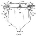
- Figure 5 can represent either a partially mated or a partially unmated condition of receptacle connector 10 and I/O connector 14.
- I/O connector 14 can be moved in the direction of arrow "C” without manually actuating or depressing the latch arms, whereupon oblique lead-in lips 76 will engage the outer edges of apertures 34 and deflect the latch arms inwardly in the direction of arrows "D" as the connectors are mated.
- overmolded portions 68 of housing 38 can be pinched inwardly in the direction of arrows "A" which, effectively, performs the same function as deflecting lips 76 inwardly in the direction of arrows "D".
- the connectors are mated with minimal forces, whereas direct mating of the connectors result in mating forces determined by the angle and radius of lead-in lips 76 and hook portions 60, respectively.
- unmating actions can be carried out in two different manners.
- a user again can pinch inwardly on overmolded portions 68 to deflect the latch arms inwardly and unmate the connectors with minimal forces as latch hooks 60 and lips 76 of the latch arms pass freely out of apertures 34.
- the connectors can be directly unmated simply by the application of opposed (unmating) forces on the connectors. These unmating forces are determined by the oblique angle of lead-in legs 76 and the size and location of the radii which define surfaces 66 of latch hooks 60.
Landscapes
- Details Of Connecting Devices For Male And Female Coupling (AREA)
Applications Claiming Priority (2)
| Application Number | Priority Date | Filing Date | Title |
|---|---|---|---|
| US287987 | 1994-08-09 | ||
| US08/287,987 US5486117A (en) | 1994-08-09 | 1994-08-09 | Locking system for an electrical connector assembly |
Publications (2)
| Publication Number | Publication Date |
|---|---|
| EP0697754A1 true EP0697754A1 (fr) | 1996-02-21 |
| EP0697754B1 EP0697754B1 (fr) | 1999-02-17 |
Family
ID=23105259
Family Applications (1)
| Application Number | Title | Priority Date | Filing Date |
|---|---|---|---|
| EP95111488A Expired - Lifetime EP0697754B1 (fr) | 1994-08-09 | 1995-07-21 | Assemblage de connecteurs électriques avec un dispositif de verrouillage |
Country Status (5)
| Country | Link |
|---|---|
| US (1) | US5486117A (fr) |
| EP (1) | EP0697754B1 (fr) |
| KR (1) | KR100198411B1 (fr) |
| DE (1) | DE69507860T2 (fr) |
| MY (1) | MY113086A (fr) |
Cited By (4)
| Publication number | Priority date | Publication date | Assignee | Title |
|---|---|---|---|---|
| NL1007765C2 (nl) * | 1997-12-11 | 1999-06-14 | Ascom Tateco Ab | Stekkerverbinding. |
| EP1257015A3 (fr) * | 2001-05-07 | 2005-03-09 | Gateway, Inc. | Connecteur pour câble d'ordinateur à montage et démontage rapide |
| EP1284525A3 (fr) * | 2001-08-02 | 2005-03-23 | Hosiden Corporation | Connecteur à fiches |
| CN106887763A (zh) * | 2017-02-24 | 2017-06-23 | 中航光电科技股份有限公司 | 一种连接器组件及其插头连接器 |
Families Citing this family (90)
| Publication number | Priority date | Publication date | Assignee | Title |
|---|---|---|---|---|
| USD381957S (en) * | 1994-05-07 | 1997-08-05 | Sony Corporation | Connector |
| DE19500102C2 (de) * | 1995-01-04 | 1999-09-30 | Itt Cannon Gmbh | Verriegelungsvorrichtung für einen Steckverbinder |
| USD372708S (en) | 1995-03-06 | 1996-08-13 | Hetherington Michael H | Computer adaptor housing |
| DE19514767C1 (de) * | 1995-04-21 | 1996-05-15 | Siemens Ag | Gekapselte Ein-/Ausgabebaugruppe |
| USD392255S (en) | 1996-02-09 | 1998-03-17 | Itt Corporation | IC card connector |
| JP3826366B2 (ja) * | 1996-02-22 | 2006-09-27 | モレックス インコーポレーテッド | 電気コネクタ |
| US5702266A (en) * | 1996-05-03 | 1997-12-30 | Molex Incorporated | Electrical connector latching system |
| DE19621614C1 (de) * | 1996-05-30 | 1997-12-18 | Itt Cannon Gmbh | Steckverbinder |
| DE29610993U1 (de) * | 1996-05-31 | 1997-10-16 | ITT Cannon GmbH, 71384 Weinstadt | Kabelstecker |
| US5941726A (en) * | 1996-11-27 | 1999-08-24 | The Whitaker Corporation | Interlocking release latching system for electrical connector |
| CN1101066C (zh) * | 1996-11-27 | 2003-02-05 | 惠特克公司 | 可安装在线路板上的同轴连接器 |
| WO1998024151A1 (fr) * | 1996-11-29 | 1998-06-04 | The Whitaker Corporation | Element de verrouillage elastique pour connecteur electrique |
| US6071141A (en) * | 1998-05-14 | 2000-06-06 | Berg Technology, Inc. | Connector latches |
| US5954531A (en) * | 1997-10-01 | 1999-09-21 | Ericsson Inc. | Releasable locking mechanism |
| DE19753521C2 (de) * | 1997-12-03 | 2000-04-06 | Amphenol Tuchel Elect | Steckverbinder |
| US5989051A (en) * | 1997-12-05 | 1999-11-23 | Viasat, Inc. | Connector for joining a cable to a PCMCIA card |
| US6244890B1 (en) * | 1998-03-27 | 2001-06-12 | Molex Incorporated | Male electrical connector for flat flexible circuit |
| JP3467185B2 (ja) * | 1998-04-08 | 2003-11-17 | 矢崎総業株式会社 | コネクタのロック機構 |
| GB9809092D0 (en) * | 1998-04-29 | 1998-06-24 | Static Systems Group Plc | A plug and a plug and a socket |
| KR100413026B1 (ko) * | 1998-04-30 | 2004-03-22 | 삼성전자주식회사 | 커넥터어셈블리 |
| US6149451A (en) * | 1998-06-12 | 2000-11-21 | Atl Technology, Inc. | Cable connector latching device |
| DE19828636C2 (de) * | 1998-06-26 | 2000-07-06 | Framatome Connectors Int | Steckverbinder mit Schnappverschluß |
| US6093057A (en) * | 1998-11-13 | 2000-07-25 | Hon Hai Precision Ind. Co., Ltd. | Connector assembly for connecting an electrical device to an external power supply |
| CN1204659C (zh) | 1999-01-26 | 2005-06-01 | 莫列斯公司 | 带有锁合机构和金属弹簧的电连接器 |
| JP2001052785A (ja) * | 1999-08-03 | 2001-02-23 | Jst Mfg Co Ltd | スライダ及びこれを含むコネクタ |
| FR2806218B1 (fr) * | 2000-03-10 | 2004-09-10 | Framatome Connectors Int | Connecteur d'entree/sortie du type fiche |
| US6352450B1 (en) | 2000-03-10 | 2002-03-05 | Cableco Technologies Corporation | Electrical connector having a single receptacle capable of receiving a plurality of plugs |
| US6264491B1 (en) * | 2000-06-05 | 2001-07-24 | Mobility Electronics | Quick release spring connector for computer cable |
| US7295443B2 (en) | 2000-07-06 | 2007-11-13 | Onspec Electronic, Inc. | Smartconnect universal flash media card adapters |
| US6438638B1 (en) | 2000-07-06 | 2002-08-20 | Onspec Electronic, Inc. | Flashtoaster for reading several types of flash-memory cards with or without a PC |
| US6273740B1 (en) | 2000-07-21 | 2001-08-14 | Mobility Electronics Inc. | Quick release spring connector adaptor for a computer cable |
| DE10104288C1 (de) * | 2001-01-30 | 2002-04-04 | Karl Lumberg Gmbh & Co Kg | Elektrische Steckverbindung |
| US6383010B1 (en) | 2001-04-23 | 2002-05-07 | Molex Incorporated | Latching system for electrical connectors |
| JP4223771B2 (ja) * | 2002-09-02 | 2009-02-12 | 日本圧着端子製造株式会社 | 逆嵌合防止コネクタ |
| USD491187S1 (en) | 2002-10-02 | 2004-06-08 | Onspec Electronic Inc. | Storage reader connector |
| TWM250358U (en) * | 2003-09-19 | 2004-11-11 | Hon Hai Prec Ind Co Ltd | Electrical connector |
| USD525585S1 (en) * | 2003-11-11 | 2006-07-25 | Apac Opto Electronics Inc. | 1×9 bi-direction optical transceiver |
| CN2728035Y (zh) * | 2004-06-23 | 2005-09-21 | 富士康(昆山)电脑接插件有限公司 | 电子转接器 |
| US7029311B2 (en) * | 2004-09-01 | 2006-04-18 | Molex Incorporated | Latch for electrical connectors |
| US20060094281A1 (en) * | 2004-11-04 | 2006-05-04 | Carlyle, Inc. | Latching electrical connector assembly |
| US7813408B2 (en) * | 2004-12-01 | 2010-10-12 | Harris Corporation | Wireless communications device with white gaussian noise generator and related methods |
| FR2884059B1 (fr) * | 2005-03-31 | 2007-05-25 | Radiall Sa | Connecteur multicontacts |
| US8109883B2 (en) | 2006-09-28 | 2012-02-07 | Tyco Healthcare Group Lp | Cable monitoring apparatus |
| US8668651B2 (en) | 2006-12-05 | 2014-03-11 | Covidien Lp | ECG lead set and ECG adapter system |
| US7753713B2 (en) * | 2007-06-12 | 2010-07-13 | Delphi Technologies, Inc. | Universal serial bus standard interface connections |
| CN101207248B (zh) * | 2007-11-27 | 2010-12-01 | 王海龙 | 自锁插头 |
| CA2646037C (fr) | 2007-12-11 | 2017-11-28 | Tyco Healthcare Group Lp | Connecteur d'electrode pour ecg |
| DE102008006433B4 (de) * | 2008-01-28 | 2011-07-28 | Airbus Operations GmbH, 21129 | Vorrichtung zur Befestigung eines Flugzeugkabinenmoduls |
| US8092246B1 (en) * | 2008-04-18 | 2012-01-10 | Lockheed Martin Corporation | Self-locking micro-D connector |
| US8052430B2 (en) * | 2008-06-09 | 2011-11-08 | Hon Hai Precision Ind. Co., Ltd. | Cable assembly having connector with interior printed circuit board facilitating termination |
| TW201014076A (en) * | 2008-09-25 | 2010-04-01 | Compal Electronics Inc | Electronic device assembly |
| USD737979S1 (en) | 2008-12-09 | 2015-09-01 | Covidien Lp | ECG electrode connector |
| TWM378534U (en) * | 2009-03-31 | 2010-04-11 | Hon Hai Prec Ind Co Ltd | Electrical connector and electrical connector assembly |
| DE102009032147B3 (de) * | 2009-07-07 | 2011-07-28 | Phoenix Contact GmbH & Co. KG, 32825 | Sicherungseinrichtung |
| US8694080B2 (en) * | 2009-10-21 | 2014-04-08 | Covidien Lp | ECG lead system |
| US7824206B1 (en) * | 2009-11-20 | 2010-11-02 | At&T Intellectual Property I, L.P. | Digital multimedia connectors that secure to corresponding digital multimedia receptacles |
| CA2746944C (fr) | 2010-07-29 | 2018-09-25 | Tyco Healthcare Group Lp | Systeme adaptateur pour ecg et methode connexe |
| DE102010034634B3 (de) * | 2010-08-17 | 2011-12-08 | Lumberg Connect Gmbh | Anschlussdose mit Halteeinrichtung für Steckverbinder |
| US8591249B2 (en) * | 2010-08-17 | 2013-11-26 | Souraiu USA, Inc. | Flexible breakaway connector |
| EP2625006B1 (fr) | 2010-10-08 | 2016-12-07 | Milwaukee Electric Tool Corporation | Système de retenue de batterie pour un outil électrique |
| DE102010042354A1 (de) * | 2010-10-12 | 2012-04-12 | Intercontec Pfeiffer Gmbh | Elektrischer Steckverbinder mit einer Abreißerhöhung sowie Verfahren zum reversiblen Verbinden und Trennen von Steckerteilen eines Steckverbinders |
| CN102543137A (zh) * | 2010-12-07 | 2012-07-04 | 鸿富锦精密工业(深圳)有限公司 | 防松脱装置及使用该防松脱装置的存储器组合 |
| CN102842813B (zh) * | 2011-06-20 | 2015-02-04 | 富士康(昆山)电脑接插件有限公司 | 电连接器及对接连接器 |
| DK2734106T3 (da) | 2011-07-22 | 2020-01-06 | Kpr Us Llc | Ekg-elektrodekonnektor |
| US8634901B2 (en) | 2011-09-30 | 2014-01-21 | Covidien Lp | ECG leadwire system with noise suppression and related methods |
| WO2013162590A1 (fr) | 2012-04-27 | 2013-10-31 | Anderson Power Products, Inc. | Mécanisme de verrouillage compact pour connecteur électrique à mi-puissance |
| KR20150011395A (ko) * | 2012-06-27 | 2015-01-30 | 야자키 소교 가부시키가이샤 | 플랙시블 멀티배선 커넥터 |
| US9093788B2 (en) * | 2012-09-28 | 2015-07-28 | Atlantic Great Dane, Inc. | Power supply system including panel with safety release |
| US9551841B2 (en) * | 2012-11-30 | 2017-01-24 | Corning Optical Communications LLC | Optical data center connector systems, fiber optic plug assemblies, and fiber optic receptacle assemblies |
| US8961217B2 (en) | 2013-03-12 | 2015-02-24 | Carlisle Interconnect Technologies, Inc. | Electrical connector assembly with integrated latching system, strain relief, and EMI shielding |
| US9083119B2 (en) * | 2013-03-14 | 2015-07-14 | Molex Incorporated | Connector having a housing with a pair of engagement arms and catch members |
| US9408546B2 (en) | 2013-03-15 | 2016-08-09 | Covidien Lp | Radiolucent ECG electrode system |
| WO2014149548A1 (fr) | 2013-03-15 | 2014-09-25 | Covidien Lp | Connecteur d'électrode à élément conducteur |
| USD771818S1 (en) | 2013-03-15 | 2016-11-15 | Covidien Lp | ECG electrode connector |
| US9520669B2 (en) | 2014-05-19 | 2016-12-13 | Yazaki North America, Inc. | Connector assembly with male terminal protector |
| JP5913485B2 (ja) * | 2014-08-29 | 2016-04-27 | 日本電信電話株式会社 | 生体信号モニタシステム |
| TWD186206S (zh) * | 2016-07-15 | 2017-10-21 | 鴻騰精密科技股份有限公司 | 電連接器 |
| DE102016122151B3 (de) * | 2016-11-17 | 2017-11-30 | Fujitsu Limited | Austauschbares Modul für ein Computersystem sowie Computersystem |
| EP3639330B1 (fr) | 2017-06-13 | 2025-03-26 | Samtec Inc. | Connecteur de câble électrique |
| USD964291S1 (en) | 2017-07-21 | 2022-09-20 | Samtec, Inc. | Electrical connector |
| WO2019018728A1 (fr) * | 2017-07-21 | 2019-01-24 | Samtec Inc. | Connecteur électrique comprenant un verrou |
| USD896183S1 (en) | 2018-01-08 | 2020-09-15 | Samtec, Inc. | Electrical cable connector |
| US10571640B2 (en) | 2018-06-22 | 2020-02-25 | Panduit Corp. | Cassette adapter and method of installation |
| WO2020010095A1 (fr) * | 2018-07-06 | 2020-01-09 | Hubbell Incorporated | Connecteur de fiche électrique et dispositif de câblage doté d'éléments de clavetage |
| CN111355100B (zh) * | 2018-12-21 | 2023-12-19 | 富士康(昆山)电脑接插件有限公司 | 插头连接器 |
| JP7330845B2 (ja) * | 2019-10-11 | 2023-08-22 | ヒロセ電機株式会社 | ロック機構付きコネクタ及びコネクタ装置 |
| US11258202B2 (en) * | 2019-10-24 | 2022-02-22 | Jonathon R. Weeks | Secure outlet device and method |
| US11569612B2 (en) * | 2020-05-09 | 2023-01-31 | Foxconn (Kunshan) Computer Connector Co., Ltd. | Electrical connector assembly having a pair of latches and a pair of buttons pivotable to operate the latches |
| USD942395S1 (en) * | 2021-01-30 | 2022-02-01 | Jiangxi Kingtron Technology Co., Ltd | Double USB C wiring connector |
| US12431666B2 (en) * | 2022-12-30 | 2025-09-30 | Roku, Inc. | Expandable accordion-style cable overmold for secure connection |
Citations (3)
| Publication number | Priority date | Publication date | Assignee | Title |
|---|---|---|---|---|
| US4621885A (en) * | 1985-09-20 | 1986-11-11 | Amp Incorporated | Ribbon cable connector with improved cover latch |
| US4762505A (en) * | 1987-04-16 | 1988-08-09 | Amp Incorporated | Positive retention connector latch |
| US5292258A (en) * | 1992-05-08 | 1994-03-08 | Yazaki Corporation | Connector assembly's locking mechanism |
Family Cites Families (23)
| Publication number | Priority date | Publication date | Assignee | Title |
|---|---|---|---|---|
| JPS5031909Y1 (fr) * | 1970-05-14 | 1975-09-17 | ||
| US3990727A (en) * | 1976-01-26 | 1976-11-09 | Stephen Franics Gallagher | Quick detachable coupler |
| US4026624A (en) * | 1976-09-03 | 1977-05-31 | Ford Motor Company | Locking structure for electrical connectors |
| DE2708998A1 (de) * | 1977-03-02 | 1978-09-07 | Licentia Gmbh | Steckbaugruppe zum einschub in einen baugruppentraeger |
| DE2909616A1 (de) * | 1979-03-12 | 1980-09-18 | Siemens Ag | Elektrische steckverbinderanordnung |
| DE3031261A1 (de) * | 1980-08-19 | 1982-04-01 | Robert Bosch Gmbh, 7000 Stuttgart | Vielpolige steckvorrichtung |
| EP0057501B1 (fr) * | 1981-01-24 | 1985-11-13 | AMP INCORPORATED (a New Jersey corporation) | Assemblage de connecteurs électriques pour montage sur une plaquette à circuit imprimé |
| JPS5971578U (ja) * | 1982-11-04 | 1984-05-15 | アンプ インコ−ポレ−テツド | 電気コネクタ組立体 |
| JPS6079683A (ja) * | 1983-10-07 | 1985-05-07 | 日産自動車株式会社 | コネクタのロツク機構 |
| US4684192A (en) * | 1986-09-18 | 1987-08-04 | Amp Incorporated | Breakaway electrical connector |
| JPH0345420Y2 (fr) * | 1987-04-30 | 1991-09-25 | ||
| US5110302A (en) * | 1988-03-15 | 1992-05-05 | Amp Incorporated | Latching means for electrical connectors |
| JPH01174877U (fr) * | 1988-05-30 | 1989-12-12 | ||
| JPH0817102B2 (ja) * | 1988-07-15 | 1996-02-21 | 日本エー・エム・ピー株式会社 | 電気コネクタ |
| JPH0733403Y2 (ja) * | 1989-12-04 | 1995-07-31 | ホシデン株式会社 | コネクタ |
| US5234357A (en) * | 1990-07-04 | 1993-08-10 | Hirose Electric Co., Ltd. | Lock mechanism for electrical connector |
| US5197901A (en) * | 1990-10-30 | 1993-03-30 | Japan Aviation Electronics Industry, Limited | Lock-spring and lock-equipped connector |
| US5201669A (en) * | 1991-09-16 | 1993-04-13 | Advanced-Connectek Inc. | Connection device of a computer connection |
| US5178556A (en) * | 1991-10-24 | 1993-01-12 | Advanced-Connectek Inc. | Computer plug connector fastening mechanism |
| US5207586A (en) * | 1991-10-24 | 1993-05-04 | Intel Corporation | Integral connector system for credit card size I/O card external connector |
| EP0552683A1 (fr) * | 1992-01-24 | 1993-07-28 | The Whitaker Corporation | Cliquet dégageable par traction au même plan pour connecteurs électriques |
| JP2903193B2 (ja) * | 1992-02-26 | 1999-06-07 | 三菱電線工業株式会社 | コネクタのロック機構 |
| JP2595670Y2 (ja) * | 1992-07-27 | 1999-05-31 | ヒロセ電機株式会社 | Icカード用電気コネクタ |
-
1994
- 1994-08-09 US US08/287,987 patent/US5486117A/en not_active Expired - Fee Related
-
1995
- 1995-07-21 EP EP95111488A patent/EP0697754B1/fr not_active Expired - Lifetime
- 1995-07-21 DE DE69507860T patent/DE69507860T2/de not_active Expired - Fee Related
- 1995-08-03 MY MYPI95002274A patent/MY113086A/en unknown
- 1995-08-04 KR KR1019950024040A patent/KR100198411B1/ko not_active Expired - Fee Related
Patent Citations (3)
| Publication number | Priority date | Publication date | Assignee | Title |
|---|---|---|---|---|
| US4621885A (en) * | 1985-09-20 | 1986-11-11 | Amp Incorporated | Ribbon cable connector with improved cover latch |
| US4762505A (en) * | 1987-04-16 | 1988-08-09 | Amp Incorporated | Positive retention connector latch |
| US5292258A (en) * | 1992-05-08 | 1994-03-08 | Yazaki Corporation | Connector assembly's locking mechanism |
Cited By (6)
| Publication number | Priority date | Publication date | Assignee | Title |
|---|---|---|---|---|
| NL1007765C2 (nl) * | 1997-12-11 | 1999-06-14 | Ascom Tateco Ab | Stekkerverbinding. |
| EP0923166A1 (fr) * | 1997-12-11 | 1999-06-16 | Ascom Tateco B.V. | Connexion à fiche et prise |
| EP1257015A3 (fr) * | 2001-05-07 | 2005-03-09 | Gateway, Inc. | Connecteur pour câble d'ordinateur à montage et démontage rapide |
| EP1284525A3 (fr) * | 2001-08-02 | 2005-03-23 | Hosiden Corporation | Connecteur à fiches |
| CN106887763A (zh) * | 2017-02-24 | 2017-06-23 | 中航光电科技股份有限公司 | 一种连接器组件及其插头连接器 |
| CN106887763B (zh) * | 2017-02-24 | 2019-06-07 | 中航光电科技股份有限公司 | 一种连接器组件及其插头连接器 |
Also Published As
| Publication number | Publication date |
|---|---|
| DE69507860D1 (de) | 1999-03-25 |
| MY113086A (en) | 2001-11-30 |
| US5486117A (en) | 1996-01-23 |
| DE69507860T2 (de) | 1999-11-04 |
| EP0697754B1 (fr) | 1999-02-17 |
| KR100198411B1 (ko) | 1999-06-15 |
Similar Documents
| Publication | Publication Date | Title |
|---|---|---|
| US5486117A (en) | Locking system for an electrical connector assembly | |
| EP0945920B1 (fr) | Connecteur pour des circuits plats et flexibles | |
| US6565383B1 (en) | Electrical connector with locking member | |
| US6655979B1 (en) | Cable end connector with locking member | |
| EP0907222A2 (fr) | Connecteur electrique blindé avec möcanisme de verrouillage | |
| JP2622935B2 (ja) | ラッチ式電気コネクタ | |
| US5702266A (en) | Electrical connector latching system | |
| US6347948B1 (en) | Cable connector assembly with improved grounding means | |
| TWI271007B (en) | Latch for electrical connector | |
| US5273453A (en) | Electrical connector with positive latch | |
| JPH06333632A (ja) | 電気コネクタ組立体 | |
| US5342215A (en) | Releasable latching system for electrical connectors | |
| US6149450A (en) | Smart card adapter latch | |
| US6773293B1 (en) | Cable end connector with locking member | |
| US5980313A (en) | System for mounting an electrical connector on a panel | |
| US6988908B2 (en) | Cable end connector assembly with a pressing device | |
| TWI294265B (en) | Connector enhanced in electromagnetic shielding function | |
| EP0713263B1 (fr) | Structure de connexion enfichable autoverrouillant | |
| US5154630A (en) | Plug connector assembly | |
| US4458973A (en) | Connector assembly having improved internal latching system | |
| US8425248B2 (en) | Plug electrical connector with elastic latch | |
| JP3463245B2 (ja) | 電気コネクタのラッチシステム | |
| US6394824B1 (en) | Electrical connector | |
| US7182626B2 (en) | Electrical connector with improved latch means | |
| WO2003021724A1 (fr) | Connecteur de cable pourvu d'un moyen de contact actionne par coulissement |
Legal Events
| Date | Code | Title | Description |
|---|---|---|---|
| PUAI | Public reference made under article 153(3) epc to a published international application that has entered the european phase |
Free format text: ORIGINAL CODE: 0009012 |
|
| AK | Designated contracting states |
Kind code of ref document: A1 Designated state(s): DE FR GB IT NL |
|
| 17P | Request for examination filed |
Effective date: 19960724 |
|
| GRAG | Despatch of communication of intention to grant |
Free format text: ORIGINAL CODE: EPIDOS AGRA |
|
| 17Q | First examination report despatched |
Effective date: 19980430 |
|
| GRAG | Despatch of communication of intention to grant |
Free format text: ORIGINAL CODE: EPIDOS AGRA |
|
| GRAH | Despatch of communication of intention to grant a patent |
Free format text: ORIGINAL CODE: EPIDOS IGRA |
|
| GRAH | Despatch of communication of intention to grant a patent |
Free format text: ORIGINAL CODE: EPIDOS IGRA |
|
| ITF | It: translation for a ep patent filed | ||
| GRAA | (expected) grant |
Free format text: ORIGINAL CODE: 0009210 |
|
| AK | Designated contracting states |
Kind code of ref document: B1 Designated state(s): DE FR GB IT NL |
|
| ET | Fr: translation filed | ||
| REF | Corresponds to: |
Ref document number: 69507860 Country of ref document: DE Date of ref document: 19990325 |
|
| PLBE | No opposition filed within time limit |
Free format text: ORIGINAL CODE: 0009261 |
|
| STAA | Information on the status of an ep patent application or granted ep patent |
Free format text: STATUS: NO OPPOSITION FILED WITHIN TIME LIMIT |
|
| 26N | No opposition filed | ||
| PGFP | Annual fee paid to national office [announced via postgrant information from national office to epo] |
Ref country code: NL Payment date: 20000620 Year of fee payment: 6 |
|
| PGFP | Annual fee paid to national office [announced via postgrant information from national office to epo] |
Ref country code: FR Payment date: 20000707 Year of fee payment: 6 |
|
| PGFP | Annual fee paid to national office [announced via postgrant information from national office to epo] |
Ref country code: GB Payment date: 20010614 Year of fee payment: 7 |
|
| PGFP | Annual fee paid to national office [announced via postgrant information from national office to epo] |
Ref country code: DE Payment date: 20010731 Year of fee payment: 7 |
|
| REG | Reference to a national code |
Ref country code: GB Ref legal event code: IF02 |
|
| PG25 | Lapsed in a contracting state [announced via postgrant information from national office to epo] |
Ref country code: NL Free format text: LAPSE BECAUSE OF NON-PAYMENT OF DUE FEES Effective date: 20020201 |
|
| PG25 | Lapsed in a contracting state [announced via postgrant information from national office to epo] |
Ref country code: FR Free format text: LAPSE BECAUSE OF NON-PAYMENT OF DUE FEES Effective date: 20020329 |
|
| NLV4 | Nl: lapsed or anulled due to non-payment of the annual fee |
Effective date: 20020201 |
|
| REG | Reference to a national code |
Ref country code: FR Ref legal event code: ST |
|
| PG25 | Lapsed in a contracting state [announced via postgrant information from national office to epo] |
Ref country code: GB Free format text: LAPSE BECAUSE OF NON-PAYMENT OF DUE FEES Effective date: 20020721 |
|
| PG25 | Lapsed in a contracting state [announced via postgrant information from national office to epo] |
Ref country code: DE Free format text: LAPSE BECAUSE OF NON-PAYMENT OF DUE FEES Effective date: 20030201 |
|
| GBPC | Gb: european patent ceased through non-payment of renewal fee |
Effective date: 20020721 |
|
| PG25 | Lapsed in a contracting state [announced via postgrant information from national office to epo] |
Ref country code: IT Free format text: LAPSE BECAUSE OF NON-PAYMENT OF DUE FEES;WARNING: LAPSES OF ITALIAN PATENTS WITH EFFECTIVE DATE BEFORE 2007 MAY HAVE OCCURRED AT ANY TIME BEFORE 2007. THE CORRECT EFFECTIVE DATE MAY BE DIFFERENT FROM THE ONE RECORDED. Effective date: 20050721 |