EP0697840B1 - Dispositif permettant de cauteriser des tissus biologiques - Google Patents
Dispositif permettant de cauteriser des tissus biologiques Download PDFInfo
- Publication number
- EP0697840B1 EP0697840B1 EP94914343A EP94914343A EP0697840B1 EP 0697840 B1 EP0697840 B1 EP 0697840B1 EP 94914343 A EP94914343 A EP 94914343A EP 94914343 A EP94914343 A EP 94914343A EP 0697840 B1 EP0697840 B1 EP 0697840B1
- Authority
- EP
- European Patent Office
- Prior art keywords
- scattering
- tissue
- optical waveguide
- liquid
- laser radiation
- Prior art date
- Legal status (The legal status is an assumption and is not a legal conclusion. Google has not performed a legal analysis and makes no representation as to the accuracy of the status listed.)
- Expired - Lifetime
Links
- 230000005855 radiation Effects 0.000 claims abstract description 65
- 239000007788 liquid Substances 0.000 claims abstract description 53
- 239000012530 fluid Substances 0.000 claims abstract description 28
- 230000003287 optical effect Effects 0.000 claims abstract description 25
- 239000013307 optical fiber Substances 0.000 claims description 25
- XLYOFNOQVPJJNP-UHFFFAOYSA-N water Substances O XLYOFNOQVPJJNP-UHFFFAOYSA-N 0.000 claims description 15
- PEDCQBHIVMGVHV-UHFFFAOYSA-N Glycerine Chemical compound OCC(O)CO PEDCQBHIVMGVHV-UHFFFAOYSA-N 0.000 claims description 14
- 238000000149 argon plasma sintering Methods 0.000 claims description 11
- 239000000203 mixture Substances 0.000 claims description 10
- 235000011187 glycerol Nutrition 0.000 claims description 7
- 239000011521 glass Substances 0.000 claims description 5
- 229920003023 plastic Polymers 0.000 claims description 5
- 230000001681 protective effect Effects 0.000 claims description 5
- 239000000523 sample Substances 0.000 claims description 5
- 230000008878 coupling Effects 0.000 claims description 4
- 238000010168 coupling process Methods 0.000 claims description 4
- 238000005859 coupling reaction Methods 0.000 claims description 4
- 229920000609 methyl cellulose Polymers 0.000 claims description 4
- 239000001923 methylcellulose Substances 0.000 claims description 4
- 235000010981 methylcellulose Nutrition 0.000 claims description 4
- 239000004033 plastic Substances 0.000 claims description 4
- 239000000560 biocompatible material Substances 0.000 claims description 3
- 230000003247 decreasing effect Effects 0.000 claims description 3
- 229940028435 intralipid Drugs 0.000 claims description 3
- 238000002156 mixing Methods 0.000 claims description 3
- 239000002872 contrast media Substances 0.000 claims description 2
- 238000006073 displacement reaction Methods 0.000 claims description 2
- 239000007924 injection Substances 0.000 claims description 2
- 238000002347 injection Methods 0.000 claims description 2
- 230000007246 mechanism Effects 0.000 claims description 2
- KIUKXJAPPMFGSW-DNGZLQJQSA-N (2S,3S,4S,5R,6R)-6-[(2S,3R,4R,5S,6R)-3-Acetamido-2-[(2S,3S,4R,5R,6R)-6-[(2R,3R,4R,5S,6R)-3-acetamido-2,5-dihydroxy-6-(hydroxymethyl)oxan-4-yl]oxy-2-carboxy-4,5-dihydroxyoxan-3-yl]oxy-5-hydroxy-6-(hydroxymethyl)oxan-4-yl]oxy-3,4,5-trihydroxyoxane-2-carboxylic acid Chemical compound CC(=O)N[C@H]1[C@H](O)O[C@H](CO)[C@@H](O)[C@@H]1O[C@H]1[C@H](O)[C@@H](O)[C@H](O[C@H]2[C@@H]([C@@H](O[C@H]3[C@@H]([C@@H](O)[C@H](O)[C@H](O3)C(O)=O)O)[C@H](O)[C@@H](CO)O2)NC(C)=O)[C@@H](C(O)=O)O1 KIUKXJAPPMFGSW-DNGZLQJQSA-N 0.000 claims 1
- 229920002674 hyaluronan Polymers 0.000 claims 1
- 229960003160 hyaluronic acid Drugs 0.000 claims 1
- 238000012544 monitoring process Methods 0.000 claims 1
- 238000000034 method Methods 0.000 abstract description 14
- 230000008569 process Effects 0.000 abstract description 5
- 210000001519 tissue Anatomy 0.000 description 57
- 239000000835 fiber Substances 0.000 description 26
- 206010028851 Necrosis Diseases 0.000 description 11
- 230000015271 coagulation Effects 0.000 description 6
- 238000005345 coagulation Methods 0.000 description 6
- 239000004744 fabric Substances 0.000 description 6
- 238000003763 carbonization Methods 0.000 description 5
- 238000005530 etching Methods 0.000 description 5
- 230000017074 necrotic cell death Effects 0.000 description 5
- 230000015572 biosynthetic process Effects 0.000 description 4
- 239000008280 blood Substances 0.000 description 4
- 210000004369 blood Anatomy 0.000 description 4
- 239000002826 coolant Substances 0.000 description 4
- 238000005253 cladding Methods 0.000 description 3
- 239000011248 coating agent Substances 0.000 description 3
- 238000000576 coating method Methods 0.000 description 3
- 238000001816 cooling Methods 0.000 description 3
- 238000010438 heat treatment Methods 0.000 description 3
- 238000010943 off-gassing Methods 0.000 description 3
- 210000002307 prostate Anatomy 0.000 description 3
- 239000000243 solution Substances 0.000 description 3
- 230000007480 spreading Effects 0.000 description 3
- 238000003892 spreading Methods 0.000 description 3
- 238000002560 therapeutic procedure Methods 0.000 description 3
- 238000012549 training Methods 0.000 description 3
- 238000002604 ultrasonography Methods 0.000 description 3
- 206010004446 Benign prostatic hyperplasia Diseases 0.000 description 2
- 208000004403 Prostatic Hyperplasia Diseases 0.000 description 2
- 238000010521 absorption reaction Methods 0.000 description 2
- 239000002253 acid Substances 0.000 description 2
- 230000008901 benefit Effects 0.000 description 2
- 230000007423 decrease Effects 0.000 description 2
- 238000013461 design Methods 0.000 description 2
- 238000011161 development Methods 0.000 description 2
- 230000018109 developmental process Effects 0.000 description 2
- 239000006185 dispersion Substances 0.000 description 2
- 238000009826 distribution Methods 0.000 description 2
- 238000002592 echocardiography Methods 0.000 description 2
- 230000004048 modification Effects 0.000 description 2
- 238000012986 modification Methods 0.000 description 2
- 230000036961 partial effect Effects 0.000 description 2
- 239000002504 physiological saline solution Substances 0.000 description 2
- 239000004417 polycarbonate Substances 0.000 description 2
- 229920000515 polycarbonate Polymers 0.000 description 2
- 238000007788 roughening Methods 0.000 description 2
- 239000002966 varnish Substances 0.000 description 2
- 241001631457 Cannula Species 0.000 description 1
- BVKZGUZCCUSVTD-UHFFFAOYSA-L Carbonate Chemical compound [O-]C([O-])=O BVKZGUZCCUSVTD-UHFFFAOYSA-L 0.000 description 1
- 208000005189 Embolism Diseases 0.000 description 1
- 229910052779 Neodymium Inorganic materials 0.000 description 1
- 206010028980 Neoplasm Diseases 0.000 description 1
- 230000002745 absorbent Effects 0.000 description 1
- 239000002250 absorbent Substances 0.000 description 1
- 230000000712 assembly Effects 0.000 description 1
- 238000000429 assembly Methods 0.000 description 1
- 230000017531 blood circulation Effects 0.000 description 1
- 210000004204 blood vessel Anatomy 0.000 description 1
- 238000009835 boiling Methods 0.000 description 1
- 238000010000 carbonizing Methods 0.000 description 1
- 230000008859 change Effects 0.000 description 1
- 230000001112 coagulating effect Effects 0.000 description 1
- 238000009792 diffusion process Methods 0.000 description 1
- 238000010790 dilution Methods 0.000 description 1
- 239000012895 dilution Substances 0.000 description 1
- 238000005315 distribution function Methods 0.000 description 1
- 230000000694 effects Effects 0.000 description 1
- 229920001903 high density polyethylene Polymers 0.000 description 1
- 239000004700 high-density polyethylene Substances 0.000 description 1
- 238000000265 homogenisation Methods 0.000 description 1
- 230000002977 hyperthermial effect Effects 0.000 description 1
- 230000002452 interceptive effect Effects 0.000 description 1
- 230000001678 irradiating effect Effects 0.000 description 1
- 239000004922 lacquer Substances 0.000 description 1
- 238000000960 laser cooling Methods 0.000 description 1
- 238000002356 laser light scattering Methods 0.000 description 1
- 238000002647 laser therapy Methods 0.000 description 1
- 230000031700 light absorption Effects 0.000 description 1
- 238000004519 manufacturing process Methods 0.000 description 1
- 239000000463 material Substances 0.000 description 1
- 230000004060 metabolic process Effects 0.000 description 1
- 210000003205 muscle Anatomy 0.000 description 1
- QEFYFXOXNSNQGX-UHFFFAOYSA-N neodymium atom Chemical compound [Nd] QEFYFXOXNSNQGX-UHFFFAOYSA-N 0.000 description 1
- 210000000056 organ Anatomy 0.000 description 1
- 230000001575 pathological effect Effects 0.000 description 1
- 238000002428 photodynamic therapy Methods 0.000 description 1
- 239000000049 pigment Substances 0.000 description 1
- 239000004810 polytetrafluoroethylene Substances 0.000 description 1
- 229920001343 polytetrafluoroethylene Polymers 0.000 description 1
- 229920002635 polyurethane Polymers 0.000 description 1
- 239000004814 polyurethane Substances 0.000 description 1
- 239000011148 porous material Substances 0.000 description 1
- 238000002360 preparation method Methods 0.000 description 1
- 230000002829 reductive effect Effects 0.000 description 1
- 230000002441 reversible effect Effects 0.000 description 1
- 238000007632 sclerotherapy Methods 0.000 description 1
- 239000000126 substance Substances 0.000 description 1
- 239000000725 suspension Substances 0.000 description 1
- 229920001169 thermoplastic Polymers 0.000 description 1
- 239000004416 thermosoftening plastic Substances 0.000 description 1
- 230000008719 thickening Effects 0.000 description 1
- 238000012546 transfer Methods 0.000 description 1
- 238000002834 transmittance Methods 0.000 description 1
- 239000002569 water oil cream Substances 0.000 description 1
Images


Classifications
-
- A—HUMAN NECESSITIES
- A61—MEDICAL OR VETERINARY SCIENCE; HYGIENE
- A61B—DIAGNOSIS; SURGERY; IDENTIFICATION
- A61B18/00—Surgical instruments, devices or methods for transferring non-mechanical forms of energy to or from the body
- A61B18/18—Surgical instruments, devices or methods for transferring non-mechanical forms of energy to or from the body by applying electromagnetic radiation, e.g. microwaves
- A61B18/20—Surgical instruments, devices or methods for transferring non-mechanical forms of energy to or from the body by applying electromagnetic radiation, e.g. microwaves using laser
- A61B18/22—Surgical instruments, devices or methods for transferring non-mechanical forms of energy to or from the body by applying electromagnetic radiation, e.g. microwaves using laser the beam being directed along or through a flexible conduit, e.g. an optical fibre; Couplings or hand-pieces therefor
- A61B18/24—Surgical instruments, devices or methods for transferring non-mechanical forms of energy to or from the body by applying electromagnetic radiation, e.g. microwaves using laser the beam being directed along or through a flexible conduit, e.g. an optical fibre; Couplings or hand-pieces therefor with a catheter
-
- A—HUMAN NECESSITIES
- A61—MEDICAL OR VETERINARY SCIENCE; HYGIENE
- A61N—ELECTROTHERAPY; MAGNETOTHERAPY; RADIATION THERAPY; ULTRASOUND THERAPY
- A61N5/00—Radiation therapy
- A61N5/06—Radiation therapy using light
- A61N5/0601—Apparatus for use inside the body
-
- A—HUMAN NECESSITIES
- A61—MEDICAL OR VETERINARY SCIENCE; HYGIENE
- A61N—ELECTROTHERAPY; MAGNETOTHERAPY; RADIATION THERAPY; ULTRASOUND THERAPY
- A61N5/00—Radiation therapy
- A61N5/06—Radiation therapy using light
- A61N5/067—Radiation therapy using light using laser light
-
- A—HUMAN NECESSITIES
- A61—MEDICAL OR VETERINARY SCIENCE; HYGIENE
- A61B—DIAGNOSIS; SURGERY; IDENTIFICATION
- A61B18/00—Surgical instruments, devices or methods for transferring non-mechanical forms of energy to or from the body
- A61B18/18—Surgical instruments, devices or methods for transferring non-mechanical forms of energy to or from the body by applying electromagnetic radiation, e.g. microwaves
- A61B18/20—Surgical instruments, devices or methods for transferring non-mechanical forms of energy to or from the body by applying electromagnetic radiation, e.g. microwaves using laser
- A61B18/22—Surgical instruments, devices or methods for transferring non-mechanical forms of energy to or from the body by applying electromagnetic radiation, e.g. microwaves using laser the beam being directed along or through a flexible conduit, e.g. an optical fibre; Couplings or hand-pieces therefor
- A61B18/28—Surgical instruments, devices or methods for transferring non-mechanical forms of energy to or from the body by applying electromagnetic radiation, e.g. microwaves using laser the beam being directed along or through a flexible conduit, e.g. an optical fibre; Couplings or hand-pieces therefor for heating a thermal probe or absorber
-
- A—HUMAN NECESSITIES
- A61—MEDICAL OR VETERINARY SCIENCE; HYGIENE
- A61B—DIAGNOSIS; SURGERY; IDENTIFICATION
- A61B18/00—Surgical instruments, devices or methods for transferring non-mechanical forms of energy to or from the body
- A61B18/18—Surgical instruments, devices or methods for transferring non-mechanical forms of energy to or from the body by applying electromagnetic radiation, e.g. microwaves
- A61B18/20—Surgical instruments, devices or methods for transferring non-mechanical forms of energy to or from the body by applying electromagnetic radiation, e.g. microwaves using laser
- A61B2018/206—Surgical instruments, devices or methods for transferring non-mechanical forms of energy to or from the body by applying electromagnetic radiation, e.g. microwaves using laser the laser light passing along a liquid-filled conduit
-
- A—HUMAN NECESSITIES
- A61—MEDICAL OR VETERINARY SCIENCE; HYGIENE
- A61B—DIAGNOSIS; SURGERY; IDENTIFICATION
- A61B18/00—Surgical instruments, devices or methods for transferring non-mechanical forms of energy to or from the body
- A61B18/18—Surgical instruments, devices or methods for transferring non-mechanical forms of energy to or from the body by applying electromagnetic radiation, e.g. microwaves
- A61B18/20—Surgical instruments, devices or methods for transferring non-mechanical forms of energy to or from the body by applying electromagnetic radiation, e.g. microwaves using laser
- A61B18/22—Surgical instruments, devices or methods for transferring non-mechanical forms of energy to or from the body by applying electromagnetic radiation, e.g. microwaves using laser the beam being directed along or through a flexible conduit, e.g. an optical fibre; Couplings or hand-pieces therefor
- A61B2018/2255—Optical elements at the distal end of probe tips
- A61B2018/2261—Optical elements at the distal end of probe tips with scattering, diffusion or dispersion of light
Definitions
- the invention relates to a device for performing the thermal desolation of biological tissue Laser radiation through a light guide into the tissue is introduced, the laser radiation by modifications in connection with the exit surface of the light guide is scattered.
- the transcutaneous introduction of the Optical fiber the so-called "bare fiber", as a rule with puncture sets, i.e. with metallic cannulas and trocars.
- the transluminal application is carried out via suitable flexible Catheters or endoscopes.
- This procedure avoids primary carbonization at the fiber end, but has the crucial disadvantage that the energy transport into the tissue only still done by heat conduction and thus in view of the large heat sink of the surrounding tissue only to very limited coagulation necrosis leads. Furthermore, the process has the major disadvantage that the pigments or chromophoric groups of the liquid absorbing the laser radiation in the radiation power used and the resulting Power densities at the fiber end also decompose photochemically or thermally and thereby trigger uncontrollable side effects.
- Tissue as the object-facing end of a beam-guiding optical waveguide is designed as a fiber optic, in a transparent end face for laser radiation, tubular envelope that is airtight and liquid-tight at the end of the object is closed, is arranged, the end of the optical waveguide due to a roughening at its distal end a stray volume Scattering device for laser radiation forms that for the laser radiation used is largely transparent. It is also disclosed that another spreader is arranged within the enveloping body or the front end of the enveloping body.
- DE-35 32 604 A1 describes a possibility for irradiating cavities in the treatment of superficial tumors in hollow organs Photodynamic therapy.
- a rigid hollow spherical radiation body is used described, which can also be used in an endoscope.
- the device of the invention described in this application serves the interstitial application of laser radiation.
- the invention has for its object to provide a device make the implementation of the method of the type mentioned above further educates that tissue sclerotherapy using laser radiation efficiently and stray liquid in the largest possible and also in non-spherical ones Treatment zones is made possible.
- the method thus improved includes the idea in the vicinity of the exit surface the laser radiation from one of its supply lines serving optical fiber in the to be desolated Tissue to meet treatment needs in size and spatial shape as closely as possible, while treatment has a substantially stable spreading range create, in which essentially no absorption, but the diffusion of the laser radiation is as diffuse as possible.
- This is the purpose of a stray fluid depot from a sufficiently viscous, in the wavelength range of the used Laser radiation essentially transparent liquid or a liquid mixture.
- the invention is based on the surprising finding that when using the device and by avoiding it the primary coagulation at the edge zone scattering liquid / tissue the diffuse spreading in the stray liquid Laser radiation deeper by a factor of 2 to 3 the tissue can penetrate, and thus clearly there in one larger volume is absorbed and this volume heating up. This occurs first after an irradiation time of several minutes in the depth of the tissue a concentric coagulation zone that another pure radiation transport into the depth of the tissue prevents, but at the same time by increased temperature very large volume of heat to take advantage of Thermal conduction for further thermal desolation of the surrounding Forms tissue.
- the tissue surrounding the fluid depot is only against End of treatment by increasing the radiation power of the laser coagulates and thus indirectly leads to a further heating of the coolant, so that even after Switch off the laser again by the inserted Liquid depot and the massive set thermal coagulation front a heat source is present, which in turn surrounding tissue via heat output thermally also in the subcoagulative range according to the Arrhenius integral damages.
- the operational procedure is chosen so that First access to the center via a probe of the tissue area to be sclerosed is found, this Procedure with simultaneous X-ray or ultrasound control can be done. Then be over this Needle depending on the size of the necrosis focus to be set later one or more dilators, the last of which Dilators with the cannula later to guide the laser beam is identical. Then this plastic dilator, which is open at the end, the biocompatible light-scattering Fluid introduced into the tissue.
- the cannula used is suitably designed so that it consists of essentially two assemblies, one of which the puncture cannula to be inserted via a probing needle itself and the second one is on this puncture cannula to be attached after removing the probing needle represents fluid-tight Y-piece, on the one hand that the laser light scattering fluid can be injected and on the other hand the optical waveguide that guides the laser light pre-adjusted fixed and via a sliding mechanism defined axially can be advanced.
- the Fluid adapted to the particular treatment situation Viscosity therefore has a sufficiently long irradiation time a suitably defined liquid depot is maintained. Therefore, common biocompatible fluids such as physiological saline because they have such a low viscosity that during the typical treatment times of 10 to 20 minutes in particular for this form of therapy upcoming tissue types such as parenchyma, muscle, prostate, etc. several 100 ml of liquid to maintain a depot would be needed. This can be done by choosing an appropriate one Avoid viscosity of the fluid.
- the fluid can be easily and inexpensively from a mixture from 0.1 to 2 parts of oil, 10 to 50 parts of water and 50 to 80 parts glycerin, the respective share totals 100.
- Execution is an oil-water-glycerine suspension used, which has the following mixing ratio: 80% glycerin, 18% water and 2% suspended oil droplets.
- a mixture of 1 to 30 parts of water and 70 to 99 parts of methyl cellulose - preferably methyl cellulose, spiked with a few percent physiological Saline - can be used.
- the numerical aperture of the optical fiber Depending on the size and geometric shape of the depot is the numerical aperture of the optical fiber to choose. Good results are seen with numerical Apertures between 0.2 and 0.6 reached. The usage an increased numerical aperture offers the possibility in a simple way also diode lasers at approx. 800 nm Energy source.
- the liquid is present one essentially transparent and one strong light-scattering component, and the components will be by means of a concentrically double-lumen cannula injected into the tissue that the transparent component about the inner and the strongly light-scattering component Be introduced over the outer lumen so that the strong light-scattering component envelops the transparent component.
- the transparent component can be glycerin and water, preferably in a mixing ratio of 80:20, and the strongly scattering component oil and water, preferably with Have 1 to 5 parts of oil in 100 parts of mixture.
- To optimize the radiation input into the fluid depot can after injection of the liquid and formation of the depot the optical fiber in the distal direction by a predetermined Amount to be moved into the deposit.
- Stray fluid depot in an elongated, in particular essentially ellipsoidal or cylindrical shape, formed and / or an optical waveguide arrangement with a such shaped radiation surface used.
- this has an optical fiber on whose surface is in a distal end portion several matted one after the other, preferably has ring-shaped areas, and its end section with one for the laser radiation transparent protective cover is provided.
- the matted areas can be one to the distal end of the optical fiber increasing roughness and / or decreasing diameter exhibit.
- the laser radiation can be coaxial to the optical waveguide arrangement Scattering - about matted - cladding tube provided his.
- a protective cover is required because of the optical fiber extreme due to the partial matting or roughening becomes sensitive to breakage. It can be done in a cost effective manner through a terminally closed and mechanically fixed Part of the optical fiber or cannula attached Precision glass or hard plastic cannula can be formed. In a practical, robust design of the catheter or the cannula encloses the entire protective cover Front part and has openings for the exit of the laser radiation scattering liquid into the tissue.
- the course of the temperature field propagation in the treated tissue can expediently be checked by continuous observation of the therapy area with a sonography device, with additional echoes depending on the temperature occurring in adjacent blood vessels in the area when the temperature here exceeds 55 ° C and thus in the blood Dissolved CO 2 intermediate outgassing and further echoes occur when water vapor bubbles occur in the aqueous component of the scattered light fluid when the temperature exceeds 95 ° C.
- the liquid can also be an X-ray contrast medium attached and an x-ray observation of education and the condition of the depot.
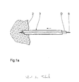
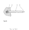
- Fig. 1a to 1d is shown schematically how the Formation of a fluid depot 1 in a body tissue section 2 by means of a cannula 3, the scattering of a a light guide 4 coupled within the cannula 3 Laser radiation in the depot 1 and the emergence of a Coagulation necrosis 5 take place according to the prior art.
- Fig. La schematically illustrates the general procedure when introducing a cannula 3 to carry out the Prior art method in the body tissue section 2: First, use a probe wire or a probing needle S access to the center of the desolating tissue areas found. Then over the probing needle 5 inserted a dilator D, and over the Dilator D finally the cannula 3. Depending on the size of the Forming necrosis focus can also be in several stages multiple dilators are set, and the last one can at the same time the laser and / or liquid-carrying Be cannula for the next steps as detailed below is described.
- the stray liquid acts at the phase boundary 1 'of the depot 1 to the tissue 2 still cooling, so that a coagulative effect is primary spreads in the depth of the tissue and that of the Depot 1 has a spaced coagulation layer 5 forms.
- the conduction heats up quasi-absorption-free stray liquid depot 1 - it so there is an energy exchange in the boundary layer area, which is symbolized in the figure by straight arrows.
- the laser radiation is in the phase outlined in FIG. 1d off.
- the heated total volume of interactive Partial volumes result in optimal expansion the inward coagulation necrosis 5, i.e. to depot 1 towards the outside, i.e. in the depth of the tissue 2 (illustrated by arrows thickening towards the end).
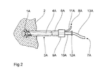
- double lumen in the form of an integrated liquid light guide such that it has a coaxial interior Lumen 4A is concentric with an outer lumen 6A is surrounded.
- the inner lumen 4A serves as Liquid light guide through which an optically transparent Component 7A of the stray liquid is supplied.
- the outer lumen 6A results in a scattering or more viscous Component 8A of the fluid to the distal end of the cannula 3A, where a fluid depot 1A is formed from both components.
- the proximal end of the cannula 3A has a branching element 9A, from which a lead 10A to the inner lumen 4A and lead 11A to the outer lumen 6A.
- the inner lumen serves as a guide shaft during the puncture phase for the probe needle for positioning the Cannula in the area to be treated.
- the cannula 3A will positioned using a puncture needle, then the puncture needle is removed and via the supply line 10A and the inner lumen 4A first the optically transparent Fluid component applied and then in a second Step over the lead 11A and the outer lumen 6A the resulting liquid depot 1A enriched with scattering medium.
- a Pinch seal 12A an optical fiber 13A to the liquid column inside the central lumen 4A this Puncture needle coupled, which then as a liquid light guide serves when over the optical fiber 13A Laser radiation is injected.
- the transparent Carrier fluid a mixture of 80% glycerin and 20% used water, which has a refractive index, the is essentially identical to the refractive index of the coupling, laser light-guiding optical fiber.
- the light-scattering medium consists of a 2 to 5% oil-water emulsion, for example intralipid in a more suitable dilution. This further training is due to the design no more contact at all between Optical fiber and fabric at risk of carbonization, but the radiation input into the tissue and the resulting deposit is a priori only through the Liquid itself.
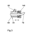
- FIG. 3 is a detailed view in longitudinal section the end section of a cannula 3A according to FIG. 2 modified cannula 3B, which is a (which in the figure not shown) continuous to the distal end Optical fiber 7B contains.
- the optical fiber 7B is with the Cap 14B firmly connected.
- the cap Via an axial displacement the cap (or when training with Union nut also turning it) is after the Introduce the cannula with pre-adjusted end with the End of the cannula, the end of the fiber extending the End of fiber from the distal end of cannula 3B by approx. 1 up to 2 mm into a litter fluid depot created there beforehand possible.
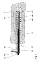
- the catheter 3C has an outer one Catheter body 15C made of transparent plastic from in a substantially cylindrical shape on its distal end is closed and closed over a distal end Provide openings 16C in an area a few cm long is. Coaxial with the outer catheter body 15C is in whose interior 6C extends almost to the distal end of the outer catheter body 15C extending at its distal End also closed inner glass cannula 17C arranged.
- the outer catheter body faces near his proximal end, which is closed with a plug 19C is, a laterally branching liquid supply 8C.
- the glass cannula 17C receives an optical fiber 7C, which in its end area of approx. 3 cm in length with several ring-shaped, each matting areas equidistant from each other 18C is provided.
- the optical fiber 7C is (which is not shown in the figure) on its proximal End connected to a laser radiation source.
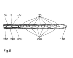
- Fig. 5 is the inner cannula 17C with the optical fiber 7C of Fig. 4 shown in more detail in an enlarged view. It can be seen how the end area of the fiber freed from their cladding 21C and coating 22C matted with an aspect ratio of 1: 1 each Alternate rings 180 and untreated fiber sections 20C.
- the frosted rings 18C point one towards the end of the fiber decreasing diameter or increasing roughness.
- the glass cannula 17C which can be made clear or matt and alternatively also made of plastic (e.g. polycarbonate) can exist, is proximal to the matting area a bond 23C with the coating 22C of the fiber and one these enveloping MRI markers 24C glued.
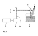
- the end of the, freed from coating and cladding Base fiber is made of an acid-resistant varnish with rings L. (Etching varnish) coated and the fiber using a Control C, a motor M and a spindle holder Sp gradually into an etching liquid E in the longitudinal direction of the fiber immersed where in the uncoated areas the Surface of the fiber is etched. Since the length of stay in the etching liquid with increasing distance of the etched Decreases areas from the fiber end, the etching depth also decreases this direction, whereby the desired course of the Roughness depth or the effective fiber diameter reached becomes. After the etching, the lacquer rings are removed.
Landscapes
- Health & Medical Sciences (AREA)
- Engineering & Computer Science (AREA)
- Biomedical Technology (AREA)
- Life Sciences & Earth Sciences (AREA)
- Veterinary Medicine (AREA)
- Nuclear Medicine, Radiotherapy & Molecular Imaging (AREA)
- Physics & Mathematics (AREA)
- Animal Behavior & Ethology (AREA)
- General Health & Medical Sciences (AREA)
- Public Health (AREA)
- Surgery (AREA)
- Radiology & Medical Imaging (AREA)
- Optics & Photonics (AREA)
- Pathology (AREA)
- Electromagnetism (AREA)
- Otolaryngology (AREA)
- Heart & Thoracic Surgery (AREA)
- Medical Informatics (AREA)
- Molecular Biology (AREA)
- Laser Surgery Devices (AREA)
- Radiation-Therapy Devices (AREA)
Claims (13)
- Appareillage pour l'oblitération thermique d'un tissu biologique (2) à l'aide d'un rayonnement laser, constitué d'un dispositif de guide d'ondes lumineuses pouvant être raccordé à une source de rayonnement laser, d'une canule à double lumière (3A), dont la lumière interne (4A) sert à faire passer des ondes lumineuses, et d'un appareillage (11A), relié à la lumière externe et à la lumière interne de la canule (3A), destiné à amener un composant (8A), ayant une grande viscosité et provoquant une forte diffusion de la lumière, et d'un composant optiquement transparent (7A) d'un liquide de diffusion, la lumière externe et la lumière interne étant ouvertes en position distale, la canule (3A) étant constituée d'un matériau biocompatible non métallique, qui pour l'essentiel n'absorbe pas le rayonnement laser et qui est constitué de façon à avoir de deux lumières concentriques, la lumière interne (4A) servant à injecter le composant optiquement transparent et la lumière externe (6A) servant à amener dans le tissu le composant (8A), assurant une forte diffusion de la lumière, du liquide de diffusion, de façon que le composant optiquement transparent (7A) soit entouré du composant (8A) assurant une forte diffusion de la lumière, des moyens étant prévus pour l'introduction ou le couplage coaxial d'un guide d'ondes lumineuses à base de fibres optiques (13A) dans ou sur la lumière interne (4A).
- Appareillage selon la revendication 1, caractérisé en ce que la canule (3) est pour l'essentiel constituée de deux sous-ensembles, dont l'un est la canule de ponction proprement dite, destinée à être introduite par l'intermédiaire d'une aiguille de sonde (S), et dont une deuxième représente un raccord en Y (9A), étanche aux fluides, devant être rapporté lui aussi à cette canule de ponction après enlèvement de l'aiguille de sonde, raccord par l'intermédiaire duquel d'une part le liquide à deux composants qui diffuse la lumière laser peut être injecté, et d'autre part le guide d'ondes lumineuses (7B) faisant passer la lumière laser peut être fixé après ajustement préalable, et être poussé vers l'avant dans une direction axiale et parfaitement définie à l'aide d'un mécanisme de poussée.
- Appareillage selon la revendication 1, caractérisé en ce que la lumière interne (4A), après noyage et injection du composant optiquement transparent du liquide de diffusion, sert lui-même de guide d'ondes lumineuses, des moyens étant prévus, au niveau de l'extrémité proximale, pour le couplage coaxial d'un guide d'ondes lumineuses à fibres optiques à la colonne de liquide du composant optiquement transparent (7A) l'intérieur de la lumière interne (4A).
- Appareillage pour l'oblitération thermique d'un tissu biologique (2) à l'aide d'un rayonnement laser, constitué d'un dispositif de guide d'ondes lumineuses (7C, 17C) pouvant être raccordé à une source de rayonnement lumineux, constitué d'un guide d'ondes lumineuses (7C) et d'un tube de gainage intérieur (17C), entourant ce guide d'ondes, de telle façon que, coaxialement à ce dispositif de guide d'ondes lumineuses (7C, 17C) soit prévu un tube de gainage externe (15C) diffusant le rayonnement laser, tube qui est constitué d'un matériau biocompatible non métallique qui pour l'essentiel n'absorbe pas le rayonnement laser, et qui guide d'une manière concentrique le dispositif de guide d'ondes lumineuses (7C, 17C), le dispositif de guide d'ondes lumineuses (7C, 17C) servant à faire passer la lumière laser, caractérisé en ce que le tube de gainage externe (15C) comporte, pour amener un composant (8A) ayant une grande viscosité et assurant une forte diffusion de la lumière dans le tissu (2), des ouverture distales, et des ouvertures latérales additionnelles (16C), par lesquelles le composant (8A), assurant une forte diffusion de la lumière, peut être amené de l'espace intérieur (6C) du tube de gainage externe (15C) dans une zone à grand volume du tissu (2), le dispositif de guide d'ondes lumineuses (7C, 17C) étant alors entouré par le composant (8A) assurant une forte diffusion de la lumière.
- Appareillage selon la revendication 4, caractérisé en ce que le dispositif de guide d'ondes lumineuses comporte une fibre optique (7C), dont la surface comporte, dans un tronçon terminal distal, plusieurs zones (18C), matées, successives dans la direction longitudinale, ayant de préférence une configuration annulaire, et en ce que le tronçon terminal est pourvu d'une gaine de protection (17C), transparente au rayonnement laser.
- Appareillage selon la revendication 5, caractérisé en ce que la gaine de protection (17C) est constituée d'un capillaire en verre de précision ou en un plastique rigide, fermé en son extrémité, et fixé à la partie, mécaniquement fixe, du guide d'ondes lumineuses (7C) ou de la canule (3C).
- Appareillage selon la revendication 5 ou 6,
caractérisé en ce que les zones matées (18C) ont une profondeur de rugosité qui augmente, et/ou un diamètre qui diminue vers l'extrémité distale de la fibre optique. - Appareillage selon l'une des revendications précédentes, caractérisé en ce que le liquide de diffusion comporte, pour former une réserve de fluide (1A), de l'huile, de l'eau ou de la glycérine, auquel cas, indépendamment du tissu (2) à oblitérer et des propriétés souhaitées de diffusion, il contient de 0,1 à 2 % d'huile, de 10 à 50 % d'eau et de 50 à 80 % de glycérine.
- Appareillage selon l'une des revendications précédentes, caractérisé en ce que le liquide de diffusion, pour former la réserve de fluide (1A), comprend un mélange de méthylcellulose et d'eau, qui, en fonction de la viscosité exigée et des propriétés de diffusion, contient de 1 à 30 % d'eau et de 70 à 99 % de méthylcellulose.
- Appareillage selon l'une des revendications précédentes, caractérisé en ce que le composant transparent (7A) est constitué de glycérine et d'eau, de préférence selon un rapport de mélange de 80:20, et le composant (8A) à forte diffusion est constitué d'huile et d'eau, de préférence contenant 1 à 5 % d'huile.
- Appareillage selon l'une des revendications précédentes, caractérisé en ce que le liquide de diffusion comprend de l'acide hyaluronique et/ou de l'Intralipid.
- Appareillage selon l'une des revendications précédentes, caractérisé en ce que des moyens sont ajoutés pour ajuster l'évolution de la propagation du champ de température dans la zone thérapeutique, ces moyens comportant un appareil de sonographie.
- Appareillage selon l'une des revendications précédentes, caractérisé par ailleurs en ce que le liquide de diffusion se voit adjoindre un agent de contraste radiographique, pour permettre une observation aux rayons X.
Applications Claiming Priority (5)
| Application Number | Priority Date | Filing Date | Title |
|---|---|---|---|
| DE4316176A DE4316176A1 (de) | 1993-05-14 | 1993-05-14 | Verfahren und Vorrichtung zur kontrollierten thermischen Verödung biologischen Gewebes |
| DE4316176 | 1993-05-14 | ||
| DE4403134 | 1994-02-02 | ||
| DE4403134A DE4403134A1 (de) | 1993-05-14 | 1994-02-02 | Kombinationsvorrichtung zur thermischen Verödung biologischen Gewebes |
| PCT/DE1994/000554 WO1994026184A1 (fr) | 1993-05-14 | 1994-05-11 | Procede et dispositif permettant de cauteriser des tissus biologiques |
Publications (2)
| Publication Number | Publication Date |
|---|---|
| EP0697840A1 EP0697840A1 (fr) | 1996-02-28 |
| EP0697840B1 true EP0697840B1 (fr) | 2004-02-18 |
Family
ID=25925915
Family Applications (1)
| Application Number | Title | Priority Date | Filing Date |
|---|---|---|---|
| EP94914343A Expired - Lifetime EP0697840B1 (fr) | 1993-05-14 | 1994-05-11 | Dispositif permettant de cauteriser des tissus biologiques |
Country Status (4)
| Country | Link |
|---|---|
| US (1) | US6143018A (fr) |
| EP (1) | EP0697840B1 (fr) |
| DE (2) | DE4403134A1 (fr) |
| WO (1) | WO1994026184A1 (fr) |
Families Citing this family (71)
| Publication number | Priority date | Publication date | Assignee | Title |
|---|---|---|---|---|
| US6676656B2 (en) | 1994-09-09 | 2004-01-13 | Cardiofocus, Inc. | Surgical ablation with radiant energy |
| US6558375B1 (en) | 2000-07-14 | 2003-05-06 | Cardiofocus, Inc. | Cardiac ablation instrument |
| DE19702898A1 (de) | 1996-04-04 | 1998-07-23 | Somatex Medizintechnische Inst | Laser-Applikationskatheter |
| US6283955B1 (en) | 1996-05-13 | 2001-09-04 | Edwards Lifesciences Corp. | Laser ablation device |
| US5980545A (en) * | 1996-05-13 | 1999-11-09 | United States Surgical Corporation | Coring device and method |
| US5807383A (en) * | 1996-05-13 | 1998-09-15 | United States Surgical Corporation | Lasing device |
| DE19630255A1 (de) * | 1996-07-26 | 1998-01-29 | Annelie Dr Ing Pfannenstein | Laserstrahlapplikator zur interstitiellen Thermotherapie |
| FR2756741B1 (fr) * | 1996-12-05 | 1999-01-08 | Cird Galderma | Utilisation d'un chromophore dans une composition destinee a etre appliquee sur la peau avant un traitement laser |
| US5947989A (en) * | 1996-12-12 | 1999-09-07 | United States Surgical Corporation | Method and apparatus for transmyocardial revascularization |
| DE19725877B4 (de) * | 1997-06-18 | 2004-02-05 | Fraunhofer-Gesellschaft zur Förderung der angewandten Forschung e.V. | Applikationsvorrichtung zum Abtragen biologischen Gewebes |
| DE19803460C1 (de) * | 1998-01-30 | 1999-08-12 | Dornier Medizintechnik | Applikationsvorrichtung für die Behandlung biologischer Gewebe mit Laserstrahlung |
| US6135996A (en) * | 1998-04-17 | 2000-10-24 | Baxter International, Inc. | Controlled advancement lasing device |
| US9033961B2 (en) | 1999-07-14 | 2015-05-19 | Cardiofocus, Inc. | Cardiac ablation catheters for forming overlapping lesions |
| US8540704B2 (en) | 1999-07-14 | 2013-09-24 | Cardiofocus, Inc. | Guided cardiac ablation catheters |
| US8900219B2 (en) | 1999-07-14 | 2014-12-02 | Cardiofocus, Inc. | System and method for visualizing tissue during ablation procedures |
| DE20003349U1 (de) * | 2000-02-24 | 2000-06-08 | Laser & Med Tech Gmbh | Vorrichtung für die thermische Behandlung von biologischem Gewebe |
| US8256430B2 (en) | 2001-06-15 | 2012-09-04 | Monteris Medical, Inc. | Hyperthermia treatment and probe therefor |
| JP2002200181A (ja) | 2000-10-31 | 2002-07-16 | Shigehiro Kubota | レーザ治療装置 |
| US6546080B1 (en) * | 2000-11-10 | 2003-04-08 | Scimed Life Systems, Inc. | Heat sink for miniature x-ray unit |
| US6554757B1 (en) | 2000-11-10 | 2003-04-29 | Scimed Life Systems, Inc. | Multi-source x-ray catheter |
| US6540720B1 (en) | 2000-11-10 | 2003-04-01 | Scimed Life Systems, Inc. | Miniature x-ray unit |
| US6540655B1 (en) * | 2000-11-10 | 2003-04-01 | Scimed Life Systems, Inc. | Miniature x-ray unit |
| US6551278B1 (en) * | 2000-11-10 | 2003-04-22 | Scimed Life Systems, Inc. | Miniature x-ray catheter with retractable needles or suction means for positioning at a desired site |
| DE10101143A1 (de) * | 2001-01-08 | 2002-07-18 | Ulrich Speck | Steriles Gewebezugangssystem |
| US7004911B1 (en) * | 2003-02-24 | 2006-02-28 | Hosheng Tu | Optical thermal mapping for detecting vulnerable plaque |
| US20060106374A1 (en) * | 2004-11-18 | 2006-05-18 | Ceramoptec Industries, Inc. | Expendable optical waveguide with use-tracking feature |
| SE0501077L (sv) * | 2005-05-12 | 2006-11-13 | Spectracure Ab | Anordning för fotodynamisk diagnos eller behandling |
| US10219815B2 (en) | 2005-09-22 | 2019-03-05 | The Regents Of The University Of Michigan | Histotripsy for thrombolysis |
| US8057408B2 (en) | 2005-09-22 | 2011-11-15 | The Regents Of The University Of Michigan | Pulsed cavitational ultrasound therapy |
| ES2456327T3 (es) * | 2006-04-12 | 2014-04-22 | Lumenis Ltd. | Sistema para la microablación de tejido |
| US9078680B2 (en) * | 2006-04-12 | 2015-07-14 | Lumenis Ltd. | System and method for microablation of tissue |
| US8628520B2 (en) * | 2006-05-02 | 2014-01-14 | Biosense Webster, Inc. | Catheter with omni-directional optical lesion evaluation |
| US8986298B2 (en) * | 2006-11-17 | 2015-03-24 | Biosense Webster, Inc. | Catheter with omni-directional optical tip having isolated optical paths |
| US8500730B2 (en) * | 2007-11-16 | 2013-08-06 | Biosense Webster, Inc. | Catheter with omni-directional optical tip having isolated optical paths |
| US20090182315A1 (en) * | 2007-12-07 | 2009-07-16 | Ceramoptec Industries Inc. | Laser liposuction system and method |
| US9693826B2 (en) * | 2008-02-28 | 2017-07-04 | Biolitec Unternehmensbeteiligungs Ii Ag | Endoluminal laser ablation device and method for treating veins |
| EP2268223B1 (fr) * | 2008-04-25 | 2019-01-02 | Dornier MedTech Laser GmbH | Dispositif à base de lumière pour le traitement endovasculaire de vaisseaux sanguins pathologiquement altérés |
| JP2012519554A (ja) * | 2009-03-05 | 2012-08-30 | サイノシュア・インコーポレーテッド | 熱的外科手術安全装置および熱的外科手術方法 |
| US8827991B2 (en) * | 2009-04-09 | 2014-09-09 | Biolitec Pharma Marketing Ltd | Medical laser treatment device and method utilizing total reflection induced by radiation |
| US8979871B2 (en) | 2009-08-13 | 2015-03-17 | Monteris Medical Corporation | Image-guided therapy of a tissue |
| WO2011022411A2 (fr) | 2009-08-17 | 2011-02-24 | Histosonics, Inc. | Récipient de milieu de couplage acoustique jetable |
| US9943708B2 (en) | 2009-08-26 | 2018-04-17 | Histosonics, Inc. | Automated control of micromanipulator arm for histotripsy prostate therapy while imaging via ultrasound transducers in real time |
| US9901753B2 (en) | 2009-08-26 | 2018-02-27 | The Regents Of The University Of Michigan | Ultrasound lithotripsy and histotripsy for using controlled bubble cloud cavitation in fractionating urinary stones |
| US8539813B2 (en) | 2009-09-22 | 2013-09-24 | The Regents Of The University Of Michigan | Gel phantoms for testing cavitational ultrasound (histotripsy) transducers |
| US8781275B2 (en) * | 2010-07-27 | 2014-07-15 | Boston Scientific Scimed, Inc. | Laser assembly with shock absorber |
| US9492113B2 (en) | 2011-07-15 | 2016-11-15 | Boston Scientific Scimed, Inc. | Systems and methods for monitoring organ activity |
| US9144694B2 (en) | 2011-08-10 | 2015-09-29 | The Regents Of The University Of Michigan | Lesion generation through bone using histotripsy therapy without aberration correction |
| WO2013052848A1 (fr) * | 2011-10-07 | 2013-04-11 | Boston Scientific Scimed, Inc. | Procédés pour détecter et traiter thermiquement des troubles du tractus urinaire inférieur |
| US9049783B2 (en) | 2012-04-13 | 2015-06-02 | Histosonics, Inc. | Systems and methods for obtaining large creepage isolation on printed circuit boards |
| US9636133B2 (en) | 2012-04-30 | 2017-05-02 | The Regents Of The University Of Michigan | Method of manufacturing an ultrasound system |
| EP2903688A4 (fr) | 2012-10-05 | 2016-06-15 | Univ Michigan | Rétroaction par doppler couleur induite par des bulles lors d'une histotripsie |
| JP5952327B2 (ja) * | 2013-03-22 | 2016-07-13 | 富士フイルム株式会社 | 光音響計測装置及び穿刺針 |
| EP4166194A1 (fr) | 2013-07-03 | 2023-04-19 | Histosonics, Inc. | Séquences d'excitation d'histotripsie optimisées pour la formation de nuage de bulles à l'aide de la diffusion de choc |
| US11432900B2 (en) | 2013-07-03 | 2022-09-06 | Histosonics, Inc. | Articulating arm limiter for cavitational ultrasound therapy system |
| US10780298B2 (en) | 2013-08-22 | 2020-09-22 | The Regents Of The University Of Michigan | Histotripsy using very short monopolar ultrasound pulses |
| US9700342B2 (en) | 2014-03-18 | 2017-07-11 | Monteris Medical Corporation | Image-guided therapy of a tissue |
| US9492121B2 (en) | 2014-03-18 | 2016-11-15 | Monteris Medical Corporation | Image-guided therapy of a tissue |
| US10675113B2 (en) | 2014-03-18 | 2020-06-09 | Monteris Medical Corporation | Automated therapy of a three-dimensional tissue region |
| JP2017513645A (ja) | 2014-04-28 | 2017-06-01 | カーディオフォーカス,インコーポレーテッド | アブレーション処置の際にicg色素組成物を用いて組織を視覚化するためのシステムおよび方法 |
| WO2016089900A2 (fr) | 2014-12-03 | 2016-06-09 | Cardiofocus, Inc. | Système et procédé de confirmation visuelle d'isolement des veines pulmonaires au cours de procédures d'ablation |
| US10327830B2 (en) | 2015-04-01 | 2019-06-25 | Monteris Medical Corporation | Cryotherapy, thermal therapy, temperature modulation therapy, and probe apparatus therefor |
| EP4230262A3 (fr) | 2015-06-24 | 2023-11-22 | The Regents Of The University Of Michigan | Systèmes de thérapie par histotripsie pour le traitement de tissu cérébral |
| CN108115283B (zh) * | 2017-12-12 | 2020-06-09 | 吉林大学 | 根据成分与工况制备耦合仿生表面的方法及热镦模具 |
| CN113286552B (zh) | 2018-11-28 | 2025-05-02 | 希斯托索尼克斯公司 | 组织摧毁术系统及方法 |
| WO2021155026A1 (fr) | 2020-01-28 | 2021-08-05 | The Regents Of The University Of Michigan | Systèmes et procédés d'immunosensibilisation par histotripsie |
| JP2023530477A (ja) | 2020-06-18 | 2023-07-18 | ヒストソニックス,インコーポレーテッド | 組織破砕音響/患者結合システムおよび方法 |
| EP4204084A4 (fr) | 2020-08-27 | 2024-10-09 | The Regents Of The University Of Michigan | Transducteur ultrasonore à capacité d'émission-réception pour l'histotripsie |
| EP4351718A4 (fr) | 2021-06-07 | 2025-03-26 | The Regents of The University of Michigan | Méthodes et systèmes d'histotripsie minimalement invasifs |
| IL308943A (en) | 2021-06-07 | 2024-01-01 | Univ Michigan Regents | All-inclusive ultrasound systems and methods that include histotripsy |
| AU2023366591A1 (en) | 2022-10-28 | 2025-04-24 | Histosonics, Inc. | Histotripsy systems and methods |
| WO2024221001A2 (fr) | 2023-04-20 | 2024-10-24 | Histosonics, Inc. | Systèmes d'histotripsie et procédés associés comprenant des interfaces utilisateur et des flux de travail pour la planification et la thérapie de traitement |
Citations (1)
| Publication number | Priority date | Publication date | Assignee | Title |
|---|---|---|---|---|
| DE4137983C2 (de) * | 1990-12-19 | 1997-03-06 | Schott Glaswerke | Applikationsvorrichtung für die Behandlung biologischer Gewebe mit Laserstrahlung |
Family Cites Families (8)
| Publication number | Priority date | Publication date | Assignee | Title |
|---|---|---|---|---|
| US4336809A (en) * | 1980-03-17 | 1982-06-29 | Burleigh Instruments, Inc. | Human and animal tissue photoradiation system and method |
| DE3323365C2 (de) * | 1982-09-04 | 1994-10-20 | Gsf Forschungszentrum Umwelt | Verfahren und Vorrichtung zur Ausleuchtung von Hohlräumen |
| JPH0741082B2 (ja) * | 1984-09-14 | 1995-05-10 | オリンパス光学工業株式会社 | レ−ザプロ−ブ |
| JPS62192715U (fr) * | 1986-05-27 | 1987-12-08 | ||
| US6066130A (en) * | 1988-10-24 | 2000-05-23 | The General Hospital Corporation | Delivering laser energy |
| DE4211526A1 (de) * | 1992-04-06 | 1993-10-07 | Berlin Laser Medizin Zentrum | Optischer Arbeitsschaft zur Photo-Thermotherapie |
| US5489279A (en) * | 1994-03-21 | 1996-02-06 | Dusa Pharmaceuticals, Inc. | Method of applying photodynamic therapy to dermal lesion |
| US5571151A (en) * | 1994-10-25 | 1996-11-05 | Gregory; Kenton W. | Method for contemporaneous application of laser energy and localized pharmacologic therapy |
-
1994
- 1994-02-02 DE DE4403134A patent/DE4403134A1/de not_active Ceased
- 1994-05-11 EP EP94914343A patent/EP0697840B1/fr not_active Expired - Lifetime
- 1994-05-11 US US08/545,864 patent/US6143018A/en not_active Expired - Fee Related
- 1994-05-11 DE DE59410356T patent/DE59410356D1/de not_active Expired - Fee Related
- 1994-05-11 WO PCT/DE1994/000554 patent/WO1994026184A1/fr not_active Ceased
Patent Citations (1)
| Publication number | Priority date | Publication date | Assignee | Title |
|---|---|---|---|---|
| DE4137983C2 (de) * | 1990-12-19 | 1997-03-06 | Schott Glaswerke | Applikationsvorrichtung für die Behandlung biologischer Gewebe mit Laserstrahlung |
Also Published As
| Publication number | Publication date |
|---|---|
| DE4403134A1 (de) | 1995-08-03 |
| WO1994026184A1 (fr) | 1994-11-24 |
| EP0697840A1 (fr) | 1996-02-28 |
| DE59410356D1 (de) | 2004-03-25 |
| US6143018A (en) | 2000-11-07 |
Similar Documents
| Publication | Publication Date | Title |
|---|---|---|
| EP0697840B1 (fr) | Dispositif permettant de cauteriser des tissus biologiques | |
| EP2004081B1 (fr) | Applicateur de laser | |
| EP0292695B1 (fr) | Dispositif d'irradiation circonférentielle d'objets | |
| DE4137983C2 (de) | Applikationsvorrichtung für die Behandlung biologischer Gewebe mit Laserstrahlung | |
| DE69226634T2 (de) | Vorrichtung mit laserlichtdurchlaessiger nadel | |
| DE68928921T2 (de) | Spendevorichtung für laserenergie | |
| DE69325692T2 (de) | Führungsdraht mit Faseroptik | |
| DE3532604C2 (fr) | ||
| DE69230409T2 (de) | Diffusionsspitze für eine optische faser | |
| DE69229128T2 (de) | Medizinische vorrichtung | |
| DE69029382T2 (de) | Vorrichtung zur bestrahlung mit einem laserstrahl | |
| DE4416902B4 (de) | Medizinische Sondenvorrichtung mit optischem Sehvermögen | |
| DE60032421T2 (de) | Laserbestrahlungsgerät | |
| DE60031209T2 (de) | Laserbestrahlungsgerät | |
| DE9190181U1 (de) | Vorrichtung zur interstitiellen Laserenergie-Lieferung | |
| DE19821986C1 (de) | Laserinstrument | |
| DE3833990C2 (de) | Ballonkatheter | |
| DE102006039471B3 (de) | Flexibler Laserapplikator | |
| DE4213053A1 (de) | Einrichtung zur Laserstrahlungsapplikation bei interstitieller Hyperthermie/Thermotherapie/photodynamischer Therapie | |
| DE102017111708B4 (de) | Apex für eine Lichtwellenleiteranordnung, chirurgisches Instrument und Lasereinheit aufweisend diesen Apex | |
| DE9006506U1 (de) | Optische Vorrichtung, insbesondere Faseroptikvorrichtung zur Verwendung mit Lasern in der Medizin | |
| DE10141487A1 (de) | Herzkatheter mit optimierter Sonde | |
| DE20003349U1 (de) | Vorrichtung für die thermische Behandlung von biologischem Gewebe | |
| DE10129029A1 (de) | Flexibler Laserapplikator zur thermischen Behandlung von biologischem Gewebe | |
| DE4211526A1 (de) | Optischer Arbeitsschaft zur Photo-Thermotherapie |
Legal Events
| Date | Code | Title | Description |
|---|---|---|---|
| PUAI | Public reference made under article 153(3) epc to a published international application that has entered the european phase |
Free format text: ORIGINAL CODE: 0009012 |
|
| 17P | Request for examination filed |
Effective date: 19951211 |
|
| AK | Designated contracting states |
Kind code of ref document: A1 Designated state(s): DE |
|
| RAP1 | Party data changed (applicant data changed or rights of an application transferred) |
Owner name: HUETTINGER MEDIZINTECHNIK GMBH & CO. KG Owner name: CERAMOPTEC GMBH |
|
| 17Q | First examination report despatched |
Effective date: 19960604 |
|
| GRAH | Despatch of communication of intention to grant a patent |
Free format text: ORIGINAL CODE: EPIDOS IGRA |
|
| RTI1 | Title (correction) |
Free format text: DEVICE FOR THERMALLY OBLITERATING BIOLOGICAL TISSUES |
|
| GRAS | Grant fee paid |
Free format text: ORIGINAL CODE: EPIDOSNIGR3 |
|
| GRAA | (expected) grant |
Free format text: ORIGINAL CODE: 0009210 |
|
| RIC1 | Information provided on ipc code assigned before grant |
Ipc: 7A 61N 5/06 B Ipc: 7A 61B 18/12 A |
|
| AK | Designated contracting states |
Kind code of ref document: B1 Designated state(s): DE |
|
| REF | Corresponds to: |
Ref document number: 59410356 Country of ref document: DE Date of ref document: 20040325 Kind code of ref document: P |
|
| PG25 | Lapsed in a contracting state [announced via postgrant information from national office to epo] |
Ref country code: DE Free format text: LAPSE BECAUSE OF NON-PAYMENT OF DUE FEES Effective date: 20041201 |
|
| PLBE | No opposition filed within time limit |
Free format text: ORIGINAL CODE: 0009261 |
|
| STAA | Information on the status of an ep patent application or granted ep patent |
Free format text: STATUS: NO OPPOSITION FILED WITHIN TIME LIMIT |
|
| 26N | No opposition filed |
Effective date: 20041119 |