EP0698373A2 - Dispositif d'occlusion d'une ouverture d'un vaisseau - Google Patents
Dispositif d'occlusion d'une ouverture d'un vaisseau Download PDFInfo
- Publication number
- EP0698373A2 EP0698373A2 EP95113341A EP95113341A EP0698373A2 EP 0698373 A2 EP0698373 A2 EP 0698373A2 EP 95113341 A EP95113341 A EP 95113341A EP 95113341 A EP95113341 A EP 95113341A EP 0698373 A2 EP0698373 A2 EP 0698373A2
- Authority
- EP
- European Patent Office
- Prior art keywords
- closure
- closure device
- locking means
- closure body
- duct
- Prior art date
- Legal status (The legal status is an assumption and is not a legal conclusion. Google has not performed a legal analysis and makes no representation as to the accuracy of the status listed.)
- Granted
Links
Images

Classifications
-
- A—HUMAN NECESSITIES
- A61—MEDICAL OR VETERINARY SCIENCE; HYGIENE
- A61B—DIAGNOSIS; SURGERY; IDENTIFICATION
- A61B17/00—Surgical instruments, devices or methods
- A61B17/12—Surgical instruments, devices or methods for ligaturing or otherwise compressing tubular parts of the body, e.g. blood vessels or umbilical cord
- A61B17/12022—Occluding by internal devices, e.g. balloons or releasable wires
-
- A—HUMAN NECESSITIES
- A61—MEDICAL OR VETERINARY SCIENCE; HYGIENE
- A61B—DIAGNOSIS; SURGERY; IDENTIFICATION
- A61B17/00—Surgical instruments, devices or methods
- A61B17/0057—Implements for plugging an opening in the wall of a hollow or tubular organ, e.g. for sealing a vessel puncture or closing a cardiac septal defect
-
- A—HUMAN NECESSITIES
- A61—MEDICAL OR VETERINARY SCIENCE; HYGIENE
- A61B—DIAGNOSIS; SURGERY; IDENTIFICATION
- A61B17/00—Surgical instruments, devices or methods
- A61B17/12—Surgical instruments, devices or methods for ligaturing or otherwise compressing tubular parts of the body, e.g. blood vessels or umbilical cord
- A61B17/12022—Occluding by internal devices, e.g. balloons or releasable wires
- A61B17/12099—Occluding by internal devices, e.g. balloons or releasable wires characterised by the location of the occluder
- A61B17/12109—Occluding by internal devices, e.g. balloons or releasable wires characterised by the location of the occluder in a blood vessel
-
- A—HUMAN NECESSITIES
- A61—MEDICAL OR VETERINARY SCIENCE; HYGIENE
- A61B—DIAGNOSIS; SURGERY; IDENTIFICATION
- A61B17/00—Surgical instruments, devices or methods
- A61B17/12—Surgical instruments, devices or methods for ligaturing or otherwise compressing tubular parts of the body, e.g. blood vessels or umbilical cord
- A61B17/12022—Occluding by internal devices, e.g. balloons or releasable wires
- A61B17/12131—Occluding by internal devices, e.g. balloons or releasable wires characterised by the type of occluding device
- A61B17/12168—Occluding by internal devices, e.g. balloons or releasable wires characterised by the type of occluding device having a mesh structure
- A61B17/12172—Occluding by internal devices, e.g. balloons or releasable wires characterised by the type of occluding device having a mesh structure having a pre-set deployed three-dimensional shape
-
- A—HUMAN NECESSITIES
- A61—MEDICAL OR VETERINARY SCIENCE; HYGIENE
- A61B—DIAGNOSIS; SURGERY; IDENTIFICATION
- A61B17/00—Surgical instruments, devices or methods
- A61B17/12—Surgical instruments, devices or methods for ligaturing or otherwise compressing tubular parts of the body, e.g. blood vessels or umbilical cord
- A61B17/12022—Occluding by internal devices, e.g. balloons or releasable wires
- A61B17/12131—Occluding by internal devices, e.g. balloons or releasable wires characterised by the type of occluding device
- A61B17/12181—Occluding by internal devices, e.g. balloons or releasable wires characterised by the type of occluding device formed by fluidized, gelatinous or cellular remodelable materials, e.g. embolic liquids, foams or extracellular matrices
-
- A—HUMAN NECESSITIES
- A61—MEDICAL OR VETERINARY SCIENCE; HYGIENE
- A61B—DIAGNOSIS; SURGERY; IDENTIFICATION
- A61B17/00—Surgical instruments, devices or methods
- A61B17/0057—Implements for plugging an opening in the wall of a hollow or tubular organ, e.g. for sealing a vessel puncture or closing a cardiac septal defect
- A61B2017/00575—Implements for plugging an opening in the wall of a hollow or tubular organ, e.g. for sealing a vessel puncture or closing a cardiac septal defect for closure at remote site, e.g. closing atrial septum defects
- A61B2017/00592—Elastic or resilient implements
-
- A—HUMAN NECESSITIES
- A61—MEDICAL OR VETERINARY SCIENCE; HYGIENE
- A61B—DIAGNOSIS; SURGERY; IDENTIFICATION
- A61B17/00—Surgical instruments, devices or methods
- A61B17/0057—Implements for plugging an opening in the wall of a hollow or tubular organ, e.g. for sealing a vessel puncture or closing a cardiac septal defect
- A61B2017/00575—Implements for plugging an opening in the wall of a hollow or tubular organ, e.g. for sealing a vessel puncture or closing a cardiac septal defect for closure at remote site, e.g. closing atrial septum defects
- A61B2017/00601—Implements entirely comprised between the two sides of the opening
-
- A—HUMAN NECESSITIES
- A61—MEDICAL OR VETERINARY SCIENCE; HYGIENE
- A61B—DIAGNOSIS; SURGERY; IDENTIFICATION
- A61B17/00—Surgical instruments, devices or methods
- A61B17/0057—Implements for plugging an opening in the wall of a hollow or tubular organ, e.g. for sealing a vessel puncture or closing a cardiac septal defect
- A61B2017/00575—Implements for plugging an opening in the wall of a hollow or tubular organ, e.g. for sealing a vessel puncture or closing a cardiac septal defect for closure at remote site, e.g. closing atrial septum defects
- A61B2017/00606—Implements H-shaped in cross-section, i.e. with occluders on both sides of the opening
-
- A—HUMAN NECESSITIES
- A61—MEDICAL OR VETERINARY SCIENCE; HYGIENE
- A61B—DIAGNOSIS; SURGERY; IDENTIFICATION
- A61B17/00—Surgical instruments, devices or methods
- A61B17/0057—Implements for plugging an opening in the wall of a hollow or tubular organ, e.g. for sealing a vessel puncture or closing a cardiac septal defect
- A61B2017/00575—Implements for plugging an opening in the wall of a hollow or tubular organ, e.g. for sealing a vessel puncture or closing a cardiac septal defect for closure at remote site, e.g. closing atrial septum defects
- A61B2017/00623—Introducing or retrieving devices therefor
-
- A—HUMAN NECESSITIES
- A61—MEDICAL OR VETERINARY SCIENCE; HYGIENE
- A61B—DIAGNOSIS; SURGERY; IDENTIFICATION
- A61B17/00—Surgical instruments, devices or methods
- A61B17/12—Surgical instruments, devices or methods for ligaturing or otherwise compressing tubular parts of the body, e.g. blood vessels or umbilical cord
- A61B17/12022—Occluding by internal devices, e.g. balloons or releasable wires
- A61B2017/1205—Introduction devices
Definitions
- the invention relates to a closure device for closing a physical anomaly such as vascular opening such as arterial duct, atrial septal defect, foramen ovale or ventricel septum defect, comprising a closure body extending inside the vascular opening and wire-shaped elastic locking means extending outside the vascular opening.
- the invention further relates to a closure device for closing a physical anomaly such as vascular opening such as arterial duct, atrial septal defect, foramen ovale or ventricel septum defect, comprising a closure body extending within the vascular opening with an axially extending middle part.
- the human blood circulation consists of a cardiovascular and a pulmonary circulation.
- the ductus arteriosus connects the aorta (body circulation) with the pulmonary artery (lung circulation).
- this duct grows after birth.
- pathological development it can happen that the duct does not overgrow, which means that the two blood circuits remain connected even after birth. This can greatly reduce the baby's life expectancy.
- a closure device of the type mentioned at the beginning can be found in DD 233 303 A1.
- the closure body has a single-shell, hyperboloid-like basic shape and can consist of metal, a metal alloy, plastic and similar materials. Extending outside the closure body are wire-shaped locking means, which end at a point, so that there is a risk of injury to the vessel walls.
- the closure device To implant the closure device, it is grasped by a holding wire extending within a securing sleeve and displaced by a catheter. Due to the shape of the closure body and the pointed ends of the locking means there is a risk of serious injury to a patient, the possibility of pulling a misplaced closure device back into the catheter.
- the present invention is based on the problem of developing a closure device of the type described above in such a way that the locking of the closure device within the vessel opening is improved and thus a secure closure is made available.
- the implantation should also be facilitated, with the possibility of correcting incorrect placement without difficulty.
- the problem is essentially solved in that the locking means are spherical or lenticular at their free ends or are provided with spherical or lenticular elements.
- the inventive design of the closure device ensures that injury to the vessel walls by the locking means is excluded. This has the advantage that a change in position of the closure is readily possible when the closure device is implanted.
- the spherical or lenticular ends of the locking means also ensure that when there is a high pressure difference between the vessels connected by the duct, the fixing elements, which normally rest against the inner walls of the vessels, cannot lead to injury due to the movement of the closure device.
- the spherical ends also prevent injury, even if the device may be transported through the vessels without securing the catheter.
- the locking elements which can also be referred to as fixing elements, preferably radiate from the closure body.
- the locking means it is possible to design the locking means as loops, which results in larger contact surfaces for the locking means on the inner walls of the vessel.
- the locking elements exerting a function of spring elements can be made of Platinum, nickel alloys, titanium or other suitable materials.
- a nickel wire with a platinum coating can also be used.
- the spherical or lenticular ends are preferably polished titanium balls or laser welding beads.
- the articulation means with the closure body are fixed in position on the face side by sewing. This ensures that the closure body cannot be moved or compressed due to the pressure difference at the ends of the vessel opening if it is a plastic part.
- the locking means can be connected via a central part extending axially within the closure body. A connection to the locking means assigned to the respective vessels can then take place through the central part.
- the middle part itself can be made in one or more parts like a telescope. Receptacles for the locking means can be formed as openings in the end sections of the middle parts.
- the end sections of the central part can be designed as separate receptacles which are connected to the central part as if welded.
- each duct should be closed as tightly and with as much implantation mass as possible. This also ensures that the space in the guide catheter is always optimally filled, i.e. the implant material (IVALON®) can only be moved onto the application forceps with a little effort.
- the invention provides that these are always sewn to the implant.
- the device can either have a central part or be designed without one.
- At least one locking means extends from its central region and / or the central part extends axially Closure body on a molding such as a clutch, which can be gripped by a pair of guide pliers.
- a molding such as a clutch
- This preferably spherical shape makes it possible for the closure device to be easily handled within a guide catheter by means of flexible guide pliers.
- a particularly noteworthy embodiment of the invention provides that between the closure device and the A safety connection such as thread exists.
- the closure body which is to be referred to as an implant
- the closure body is designed to be rotationally symmetrical and, at least in some areas, frustoconical.
- the implant is inserted in such a way that a tapered side of the implant points towards the vessel with less pressure.
- the surface with an enlarged cross section points towards the vessel with increased pressure.
- the shunt connection is thereby sealed like a wedge. Slipping of the implant within the shunt connection can also be avoided.
- the implant can have a cylindrical base region and a frustoconical tip region, the frustoconical tip region having a surface that either follows a truncated cone shell or a concave shape.
- the base region has a base surface with a diameter D1 which is at least 4 mm larger than an average diameter MD of the implant.
- the mean diameter MD is in the middle of the axial extension of the implant measured at the frustoconical tip area.
- metal wires or bristles projecting from the central part of the closure body and forming a brush-like body.
- a vessel opening is not immediately closed.
- the protruding bristles or wires damage the wall of the opening, which promotes thrombus formation and thus closes the opening.
- plastic fiber threads can also originate from the central part, which also supports thrombus formation.
- wires or bristles extending from the central part also extend outside the vessel opening, these should be end-shaped in the manner described above in the manner of lenses or spheres in order to rule out damage to the vessel walls in this area.
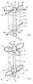
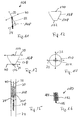
- Fig. 1 shows a first embodiment of a closure device (10), which - without the invention being restricted thereby - is referred to as a duct closure.
- the duct closure (10) unifies a locking device (12) and a preferably cylindrical implant (14) as the closure body.
- the implant (14) can consist of a foam material such as IVALON®, which is characterized in that it is well absorbed by the human body and forms a connection with the surrounding vascular tissue.
- the closure body (14) closing a vessel opening has an opening (16) which is designed to receive the locking device (12).
- the closure body (14) also axially enclose the locking device (12).
- the locking device (12) has a central part (18) which, in a first embodiment, is made in one piece.
- the middle part (18) has end regions (20), (22) into which openings (24), (26), (28) are made, which are used to hold locking means - also fixing elements (30), (32), ( 34) called - serve.
- the central part (18) has a spherical or cylindrical coupling element (38) at an end region (22), preferably spaced apart by a web (36) or a constriction.
- the central part (18), the web (36) and the spherical coupling (38) have a common central axis.
- the middle part (18) is preferably ground or turned from one part, a round material, eg. B. made of titanium or another material such as platinum alloy, with a diameter of about 1 mm to achieve a high degree of flexibility between the end regions (20), (22) to a diameter of about 0.4 mm - 0.6 mm or is rotated.
- the end regions (20), (22) can have a spherical or cylindrical shape.
- the openings (24), (26) made in the end regions (20) run one above the other and are preferably offset from one another by an angle of 90 °.
- the fixing elements (30), (32), (34) can consist of highly elastic titanium wire and have polished laser welding beads (40) at their ends in order to avoid injuries to the vessel walls.
- the ends can also be provided with polished titanium balls, which have a blind hole of approximately 0.3 mm - 0.4 mm in diameter and are welded to the ends of the wire-shaped fixing elements (30), (32), (34).
- Fig. 2 shows a second embodiment of a duct closure (22), which is essentially a modified design of a locking device (44) the embodiment of FIG. 1 differs.
- the locking device (44) has a central part (46), at the ends of which brackets (48), (50) are fastened as welded.
- the brackets (48), (50) have a cylindrical shape and have receptacles (52), (54) for the central part (47).
- a web (56) is molded onto the holder (50) on the side opposite the receptacle (52) and merges into a spherical coupling (58). 1, the center piece (47), the web (56) and the spherical coupling (58) lie on a common central axis.
- the brackets (48), (50) furthermore have receptacles (60) for receiving locking means or fixing or holding elements (62), (64), (66), (68), (70).
- the receptacles (60) are introduced into outer surfaces (72), (74) of the holders (48), (50) lying on a circumferential line.
- the fixing or holding elements (62), (64), (66), (68), (70) are each fastened with their ends in the receptacles (60) of the holding elements (48), (50) .
- the holding or fixing elements (62), (64), (66), (68), (70), which preferably consist of highly elastic titanium wire, are mechanically fixed in the receptacles (60).
- the preferred loop-shaped design of the fixing or holding elements (62), (64), (66), (68), (70) prevents injuries to vessel walls. This also results in the largest possible contact surface on the inner walls of the vessel.
- FIG. 3 shows the duct closure (10) according to FIG. 1 inserted in a guide catheter (74).
- the duct closure (10) lies with its curved fixing elements (30), (32), (34) and the polished laser welding beads or titanium balls ( 40) on an inner wall (76) of the catheter (74).
- the punctiform contact of the duct closure (10) within the catheter (74) enables the duct closure (10) to be moved easily.
- the cylindrical sealing implant such as IVALON® can be easily inserted into the catheter (74) together with the locking device (12), (44).
- the duct closure (10) is held by a flexible guide forceps (78) which is attached to the spherical or cylindrical Coupling (38) of the duct lock (10) engages, held.
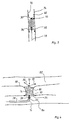
- Fig. 4 shows the duct closure (10) introduced into a duct (80).
- the duct closure (10) is introduced into the duct (80) via the catheter (74), for example from a leg vein via the inferior vena cava, right atrium, right chamber and pulmonary artery (84).
- the catheter (74) or the guiding forceps (78) have diameters which are in the range from 2 mm to 6 mm. Especially with small diameters, e.g. 2.5 mm, it is also possible to treat infants and young children.
- the duct (80) forms the connection between a vessel (82) such as the aorta and another vessel (84) such as the pulmonary artery.
- the duct lock (10) is inserted into the duct (80) by means of the catheter (74).
- the catheter (74) with inserted duct closure (10) is inserted through the pulmonary artery (84) into the duct (80) until an upper edge (86) of the catheter (74) protrudes into the aorta (82).
- the duct lock (10) lies at the level of the duct (80).
- the wall (76) of the catheter (74) is then moved towards the artery (84) with the position of the duct closure (10) held constant, as a result of which the fixing elements (30), (32) move against an inner wall (88) of the aorta ( 82) can create.
- the implant (14) is then exposed so that it can adapt to the inner wall (90) of the duct (80).
- the position of the duct lock (10) is kept constant by the guide pliers (78), which engage the coupling (38) of the duct lock (10).
- the fixing element (34) facing the pulmonary artery (84) is finally exposed, which can thus adapt to the inner wall (92) of the pulmonary artery (84).
- the implant (14) swells due to contact with liquid such as blood, so that the duct (80) is sealed.
- the fixing elements (30), (32), (34) lying against the inner walls (88), (92) cause an axial displacement of the implant (14) due to the high pressure difference between the vessels (82, 84) prevented.
- the implant (14) is sewn to the locking device (12) by means of suture material. This prevents a relative movement between the implant (14) and the locking device (12).
- the flexible can Guide forceps (78) are loosened from the spherical coupling (38) and removed from the pulmonary artery (84).
- the geometry of the implant (14) is designed such that the end regions (20), (22) and the fixing elements (30), (32), (34) are at least partially surrounded by the swollen implant material. The device according to the invention can thus be used to implement a secure duct closure in a simple and inexpensive manner.
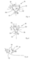
- implants (94), (96) are rotationally symmetrical bodies which are frustoconical at least in some areas and preferably consist of a foam such as Ivalon®.
- the implants (94), (96) essentially consist of a cylindrical base region (98), (100), which is followed by a frustoconical tip region (102), (104).
- the cylindrical base region (98), (100) has a diameter D1 in the range of, for example, 12 to 14 mm, which, however, is preferably at least 4 mm larger than an average diameter MD of the implant (94), (96).
- a diameter of the frustoconical tip region (102), (104) is defined as the mean diameter MD, which is determined in the middle between the base surface (99), (101) and the end surface (110), (112).
- the end surface (110), (112) has a diameter D2, which is preferably in the range between 4 and 6 mm.
- the cylindrical base region (98), (100) has a height H, which is preferably 2 mm.
- the cylindrical base region (98) is followed by a frustoconical tip region (102), the surface (106) of which follows the shape of a truncated cone shell.
- the frustoconical tip region (104) according to FIG. 6 can have a surface (108) which is concave.
- the flexible insertion forceps (78) for the duct closure (10), (42) is shown.
- the insertion forceps (78) has a forceps body (114) which is connected to a handle (118) via a flexible intermediate piece (116).
- the pliers body (114) consists of two cup-shaped claw elements (120), (122) which are connected to an actuating ring (124) of the handle (118) via a linkage (not shown) which runs within the flexible intermediate piece (116) stands.
- the shell-shaped claw elements (120), (122) can be closed by moving the actuating ring (124) in the direction of the arrow (126). A movement of the actuating ring (124) in the direction of the arrow (128), on the other hand, causes the claw elements (120), (122) to open.
- the actuating ring (124) can be locked by a threaded sleeve (130).
- a threaded sleeve 130
- the guide pliers (78) themselves can be held using a holder ring (132).
- the claw elements (120), (122) each have recesses (134), (136) which, when the claw position is closed, form a preferably circular opening (138) in the axial direction of the insertion forceps (78).
- the opening (138) serves to receive the locking means (12), (44) integrally formed web (36), (56), on which the projection (38), (58) is integrally formed like a coupling in the axial extent.
- the molded part (38), (58) is located in a cavity (140) formed by the trough-shaped claws.
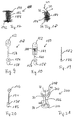
- FIG. 7c shows a side view of the claw element (122).
- the claw wall has an opening (142) for receiving a security thread (144) which serves to lock the duct closure (10), (42).
- Fig. 8 shows the securing of the duct lock (10) by means of the security thread (144) on the insertion forceps (78).
- the security thread (144) is guided through the implant (102) and knotted with one end (146) in the opening (142) of the claw element (122).
- the duct lock (10) is also secured by the security thread (144) if the claw elements (120), (122) open unintentionally or if it slips after being decoupled. This reduces the risk of embolism.
- the safety thread (144) is easily pulled through the guide catheter again with the insertion forceps (78).
- middle parts (148) and (150) which extend in the axial direction of a closure body and have end reinforcements (152), (154) which are traversed by locking or fixing means (not shown) are and are connected to them in a mechanical manner.
- the locking means should be sewn to the closure body by triple or double stitching with three knots in order to prevent relative movement of the closure body along the middle part (148) and (150).
- the central part (148) extends with a web-shaped central section (156), within a closure body, not shown.
- the cross-section-enlarged end regions (152) and (154) run at least when the closure device is not implanted outside the closure body.
- each middle part (148), (150) in connection with FIGS. 1, 2, 3 and 4 and serving as a coupling (158) has around the middle part ( 148), (150) and thus the respective closure device to be grasped by an insertion forceps.
- the embodiment according to FIG. 10 can be changed in length in that a web-shaped lower section (160) is telescopically adjustable to the upper and first surrounding section (162). There is preferably a connection between the outer section (162) and the web-shaped inner section (160) via a tension spring (164), which results in an optimal adaptation to the length of a duct to be closed.
- FIG. 11 shows a locking device (166) for a closure device, which can also be referred to as a scaffold, which comprises a central part (148) corresponding to FIG. 9, for example, and locking or fixing elements (30), (32 ), (34) with end polished titanium balls (40).
- a corresponding scaffold (164) is now surrounded by a closure body (168), preferably made of IVALON® and to be designated as a plug, which corresponds to that of FIG. 5, so that reference is made to the relevant statements.
- the locking means (30), (32) and (34) are connected to the end faces (170), (172) of the closure body (168).
- the upper and star-shaped locking elements (30), (32) by means of double seam with three knots, the single-beam locking means (34) are fixed to the end face (172) by means of a triple seam with three knots.
- the corresponding connections are indicated purely in principle by the reference symbols (174) (double seam with three knots) and (176) (triple seam with three knots).
- the preferred embodiment of the closure device shown in FIGS. 11 to 14 does not necessarily have to have the central part (148). Rather, the locking means (30), (32), (34) can be fixed to the closure body (168) solely by sewing them on.
- FIG. 15 A closure device corresponding to the structure of FIGS. 11-14 is shown in FIG. 15 in a position inserted in a guide catheter (74). It can be seen that the plug (168) lies against the inner walls of the catheter (74) and that the locking elements (30), (32) and (34) with their ends (40) consisting of titanium balls on the inner wall of the guide catheter (74 ) issue. Furthermore, the closure device is gripped by means of flexible guiding and fixing pliers (78) via the spherical projection (158). Furthermore, the closure device is connected to the fixing pliers (78) via the security thread (144).
- the frustoconical shape of the plug (168) also has the advantage that the closure device can be pulled back into the guide catheter (74) after the closure device has been removed from it without risk of injury, since the lower locking elements ( 34) can initially rest on the frustoconical section (178) of the plug (168), since there is a free space between the latter and the guide catheter (74); because the diameter of the end face (172) should be smaller than the inside diameter of the guide catheter (74).
- 16-20 are particularly noteworthy developments of closure devices to remove a vessel opening.
- One of the closure devices (180) shown in FIG. 16 consists of a central part (182) which is coiled as shown in FIGS. 19 and 20 and from which inherently stiff but elastic threads, wires or bristles emanate around a brush-like closure body which forms a closure body Form body (184).
- the protruding threads, wires or bristles should preferably consist of plastic.
- the brush (184) has a cylindrical shape, the threads, wires or bristles leading to injury to the wall inside the vessel opening to an extent such that thrombus formation is promoted when the closure device is introduced into a vessel opening.
- further fibers or other plastic elements can originate from the central part (162), which supports thrombus promotion.
- the middle part (182) has a molded part (186) in order to be gripped by a pair of pliers, as described above.
- FIG. 17 differs from that in FIG. 16 in that longer bristles or wires (190), (192), preferably made of platinum, extend above and below the cylindrical closure body (184), Extend platinum alloy or titanium, which perform the function of the locking means (30), (32), (34) according to FIG. 11 and wax into the end walls of the vessel.
- corresponding locking means (30), (32) and (34) with spherical or lenticular ends (40) made of, for example, titanium can be provided.
- Thrombogenic synthetic threads, fiberglass threads or threads made of natural materials such as cotton can also originate from the middle part (182).
- FIGS. 19 and 20 Middle parts of the closure devices (180), (188) are shown enlarged in FIGS. 19 and 20. It can thus be seen that the central part (182) shown in FIG. 19 is coiled and has the molding (186) on the end.
- the molded part (186) is then located below the enlarged section (198).
- a closure device 200
- the scaffold (166) for example shown in FIG. 11
- a closure body for example made of IVALON®, so that this consists of a central incised section (204) and outer expanded sections (206) and (208).
- the latter sections (206), (208) extend with the locking means (30), (32), (34) running in them and the end balls (40), which are made, for example, of polished titanium, outside the vessel opening to be closed.
- the tapered area (204) then represents the actual closure body.
- closure body itself preferably has a cylindrical or truncated cone shape based on the exemplary embodiments, other geometries are also conceivable; because the shape itself essentially depends on that of the defect to be closed, such as the opening of the vessel. However, a truncated cone shape is preferred for the reasons described above.
- the locking or fixing elements can be straight. Spiral or curved shapes are also conceivable.
- the locking means can also consist of textile or glass fibers or have appropriate materials. Also a coating with plastic or metal is possible.
- the closure body itself can consist of plastic, metal, ceramic or other suitable biocompatible materials. It is also conceivable that the closure body shows a round, square, hexagonal or octagonal geometry in cross section.
Landscapes
- Health & Medical Sciences (AREA)
- Surgery (AREA)
- Life Sciences & Earth Sciences (AREA)
- Public Health (AREA)
- Veterinary Medicine (AREA)
- Engineering & Computer Science (AREA)
- Biomedical Technology (AREA)
- Heart & Thoracic Surgery (AREA)
- Medical Informatics (AREA)
- Molecular Biology (AREA)
- Animal Behavior & Ethology (AREA)
- General Health & Medical Sciences (AREA)
- Nuclear Medicine, Radiotherapy & Molecular Imaging (AREA)
- Reproductive Health (AREA)
- Vascular Medicine (AREA)
- Cardiology (AREA)
- Closures For Containers (AREA)
- Surgical Instruments (AREA)
- Pipe Accessories (AREA)
- Prostheses (AREA)
- Pressure Vessels And Lids Thereof (AREA)
- Refuse Collection And Transfer (AREA)
- Details Of Indoor Wiring (AREA)
- Air-Flow Control Members (AREA)
- Duct Arrangements (AREA)
Applications Claiming Priority (4)
| Application Number | Priority Date | Filing Date | Title |
|---|---|---|---|
| DE9413645U | 1994-08-24 | ||
| DE19949413645 DE9413645U1 (de) | 1994-08-24 | 1994-08-24 | Vorrichtung zum Verschließen eines Ductus, insbesondere des Ductus arteriosus |
| DE29500381U DE29500381U1 (de) | 1994-08-24 | 1995-01-11 | Vorrichtung zum Verschließen eines Ductus, insbesondere des Ductus arteriosus |
| DE29500381U | 1995-01-11 |
Publications (3)
| Publication Number | Publication Date |
|---|---|
| EP0698373A2 true EP0698373A2 (fr) | 1996-02-28 |
| EP0698373A3 EP0698373A3 (fr) | 1996-06-12 |
| EP0698373B1 EP0698373B1 (fr) | 2003-11-05 |
Family
ID=25962369
Family Applications (1)
| Application Number | Title | Priority Date | Filing Date |
|---|---|---|---|
| EP95113341A Expired - Lifetime EP0698373B1 (fr) | 1994-08-24 | 1995-08-24 | Dispositif d'occlusion d'une ouverture d'un vaisseau |
Country Status (3)
| Country | Link |
|---|---|
| EP (1) | EP0698373B1 (fr) |
| AT (1) | ATE253326T1 (fr) |
| DE (2) | DE29500381U1 (fr) |
Cited By (8)
| Publication number | Priority date | Publication date | Assignee | Title |
|---|---|---|---|---|
| WO1999007289A1 (fr) | 1997-08-08 | 1999-02-18 | Cardia, Inc. | Dispositif d'occlusion pour l'obturation d'une anomalie physique |
| EP1174097A3 (fr) * | 2000-07-20 | 2003-01-29 | Dr. Osypka GmbH | Dispositif pour fermer la communication entre l'aorte et le conduit pulmonalis |
| BE1016067A3 (fr) * | 2004-06-03 | 2006-02-07 | Frid Noureddine | Endoprothese luminale pour occlusion d'anevrisme et procede de fabrication d'une telle endoprothese. |
| DE102005053906A1 (de) * | 2005-11-11 | 2007-05-24 | Occlutech Gmbh | Occlusionsinstrument und Operationsbesteck sowie Verfahren zu dessen Im- und Explantation |
| WO2010130617A1 (fr) * | 2009-04-16 | 2010-11-18 | Occlutech Gmbh | Implant, implant médical, et procédé de délivrance d'un implant médical |
| US7955354B2 (en) | 2005-11-14 | 2011-06-07 | Occlutech Gmbh | Occlusion device and surgical instrument and method for its implantation/explantation |
| EP2609872B2 (fr) † | 2009-05-06 | 2019-01-02 | Occlutech Holding AG | Dispositif médical pour fournir un implant médical |
| CN111658026A (zh) * | 2020-06-16 | 2020-09-15 | 上海形状记忆合金材料有限公司 | 头端环抱式夹紧输送系统 |
Families Citing this family (14)
| Publication number | Priority date | Publication date | Assignee | Title |
|---|---|---|---|---|
| US7883539B2 (en) | 1997-01-02 | 2011-02-08 | Edwards Lifesciences Llc | Heart wall tension reduction apparatus and method |
| US6183411B1 (en) | 1998-09-21 | 2001-02-06 | Myocor, Inc. | External stress reduction device and method |
| US6050936A (en) | 1997-01-02 | 2000-04-18 | Myocor, Inc. | Heart wall tension reduction apparatus |
| US5961440A (en) * | 1997-01-02 | 1999-10-05 | Myocor, Inc. | Heart wall tension reduction apparatus and method |
| US6332893B1 (en) | 1997-12-17 | 2001-12-25 | Myocor, Inc. | Valve to myocardium tension members device and method |
| US6260552B1 (en) | 1998-07-29 | 2001-07-17 | Myocor, Inc. | Transventricular implant tools and devices |
| US6723038B1 (en) | 2000-10-06 | 2004-04-20 | Myocor, Inc. | Methods and devices for improving mitral valve function |
| DE60227676D1 (de) | 2001-09-07 | 2008-08-28 | Mardil Inc | Verfahren und gerät für die externe herzstabilisierung |
| US6764510B2 (en) | 2002-01-09 | 2004-07-20 | Myocor, Inc. | Devices and methods for heart valve treatment |
| US7112219B2 (en) | 2002-11-12 | 2006-09-26 | Myocor, Inc. | Devices and methods for heart valve treatment |
| US9220487B2 (en) | 2006-08-09 | 2015-12-29 | Coherex Medical, Inc. | Devices for reducing the size of an internal tissue opening |
| US8529597B2 (en) | 2006-08-09 | 2013-09-10 | Coherex Medical, Inc. | Devices for reducing the size of an internal tissue opening |
| US8167894B2 (en) | 2006-08-09 | 2012-05-01 | Coherex Medical, Inc. | Methods, systems and devices for reducing the size of an internal tissue opening |
| CH701269A1 (de) * | 2009-06-10 | 2010-12-15 | Carag Ag | Okkluder. |
Family Cites Families (13)
| Publication number | Priority date | Publication date | Assignee | Title |
|---|---|---|---|---|
| US3874388A (en) * | 1973-02-12 | 1975-04-01 | Ochsner Med Found Alton | Shunt defect closure system |
| US4007743A (en) * | 1975-10-20 | 1977-02-15 | American Hospital Supply Corporation | Opening mechanism for umbrella-like intravascular shunt defect closure device |
| JPS549482A (en) * | 1977-06-22 | 1979-01-24 | Senko Med Instr Mfg | Catheter |
| DD233303A1 (de) * | 1984-12-28 | 1986-02-26 | Univ Berlin Humboldt | Verschlusskoerper fuer blutgefaesse und verfahren zu seiner einfuehrung |
| US4917089A (en) * | 1988-08-29 | 1990-04-17 | Sideris Eleftherios B | Buttoned device for the transvenous occlusion of intracardiac defects |
| US5354295A (en) * | 1990-03-13 | 1994-10-11 | Target Therapeutics, Inc. | In an endovascular electrolytically detachable wire and tip for the formation of thrombus in arteries, veins, aneurysms, vascular malformations and arteriovenous fistulas |
| US5108420A (en) * | 1991-02-01 | 1992-04-28 | Temple University | Aperture occlusion device |
| DE69226841T2 (de) * | 1991-11-05 | 1999-05-20 | Children's Medical Center Corp., Boston, Mass. | Okklusionsvorrichtung zur Reparatur von Herz- und Gefäss-Defekten |
| US5334137A (en) * | 1992-02-21 | 1994-08-02 | Eagle Vision, Inc. | Lacrimal fluid control device |
| DE4222291C1 (de) * | 1992-07-07 | 1994-01-20 | Krmek Mirko | Prothese zum Verschließen eines Atrial- oder eines Ventricular-Septal-Defektes und Katheter zum Einbringen der Prothese |
| US5382259A (en) * | 1992-10-26 | 1995-01-17 | Target Therapeutics, Inc. | Vasoocclusion coil with attached tubular woven or braided fibrous covering |
| US5382260A (en) * | 1992-10-30 | 1995-01-17 | Interventional Therapeutics Corp. | Embolization device and apparatus including an introducer cartridge and method for delivering the same |
| DE9413645U1 (de) * | 1994-08-24 | 1994-10-27 | Schneidt, Bernhard, Ing.(grad.), 63571 Gelnhausen | Vorrichtung zum Verschließen eines Ductus, insbesondere des Ductus arteriosus |
-
1995
- 1995-01-11 DE DE29500381U patent/DE29500381U1/de not_active Expired - Lifetime
- 1995-08-24 DE DE59510820T patent/DE59510820D1/de not_active Expired - Lifetime
- 1995-08-24 AT AT95113341T patent/ATE253326T1/de not_active IP Right Cessation
- 1995-08-24 EP EP95113341A patent/EP0698373B1/fr not_active Expired - Lifetime
Cited By (13)
| Publication number | Priority date | Publication date | Assignee | Title |
|---|---|---|---|---|
| WO1999007289A1 (fr) | 1997-08-08 | 1999-02-18 | Cardia, Inc. | Dispositif d'occlusion pour l'obturation d'une anomalie physique |
| EP1174097A3 (fr) * | 2000-07-20 | 2003-01-29 | Dr. Osypka GmbH | Dispositif pour fermer la communication entre l'aorte et le conduit pulmonalis |
| BE1016067A3 (fr) * | 2004-06-03 | 2006-02-07 | Frid Noureddine | Endoprothese luminale pour occlusion d'anevrisme et procede de fabrication d'une telle endoprothese. |
| DE102005053906A1 (de) * | 2005-11-11 | 2007-05-24 | Occlutech Gmbh | Occlusionsinstrument und Operationsbesteck sowie Verfahren zu dessen Im- und Explantation |
| US7955354B2 (en) | 2005-11-14 | 2011-06-07 | Occlutech Gmbh | Occlusion device and surgical instrument and method for its implantation/explantation |
| US9993234B2 (en) | 2009-04-16 | 2018-06-12 | Occlutech Holding Ag | Implant, medical implant, and method for delivery of a medical implant |
| WO2010130617A1 (fr) * | 2009-04-16 | 2010-11-18 | Occlutech Gmbh | Implant, implant médical, et procédé de délivrance d'un implant médical |
| US11571198B2 (en) | 2009-04-16 | 2023-02-07 | Maslanka Patentverwaltung Gmbh | Implant, medical implant, and method for delivery of a medical implant |
| US12082799B2 (en) | 2009-04-16 | 2024-09-10 | Maslanka Patentverwaltung Gmbh | Implant, medical implant, and method for delivery of a medical implant |
| EP2609872B2 (fr) † | 2009-05-06 | 2019-01-02 | Occlutech Holding AG | Dispositif médical pour fournir un implant médical |
| US11213282B2 (en) | 2009-05-06 | 2022-01-04 | Occlutech Holding Ag | Implant, medical implant, and method for delivery of a medical implant |
| CN111658026A (zh) * | 2020-06-16 | 2020-09-15 | 上海形状记忆合金材料有限公司 | 头端环抱式夹紧输送系统 |
| EP4005501A4 (fr) * | 2020-06-16 | 2022-11-16 | Shanghai Shape Memory Alloy Co., Ltd. | Système de serrage et de transport de type à enveloppe de tête de ligne |
Also Published As
| Publication number | Publication date |
|---|---|
| EP0698373A3 (fr) | 1996-06-12 |
| EP0698373B1 (fr) | 2003-11-05 |
| ATE253326T1 (de) | 2003-11-15 |
| DE29500381U1 (de) | 1995-07-20 |
| DE59510820D1 (de) | 2003-12-11 |
Similar Documents
| Publication | Publication Date | Title |
|---|---|---|
| EP0698373B1 (fr) | Dispositif d'occlusion d'une ouverture d'un vaisseau | |
| DE60133081T2 (de) | Implantat zum schliessen von defektöffnungen im menschlichen oder tierischen körper und vorrichtung zum einsetzen eines solchen implantats | |
| DE69936415T2 (de) | Gefässwundverschluss und Katheter | |
| DE29714242U1 (de) | Verschlußeinrichtung zum Verschließen einer körperlichen Anomalie wie Gefäßöffnung oder Öffnung in einer Scheidewand | |
| DE69612507T2 (de) | Selbstzentrierende, schirmartige vorrichtung zum verschliessen eines septal-defektes | |
| DE102008015781B4 (de) | Vorrichtung zum Verschluss von Defekten im Gefäßsystem | |
| DE69932996T2 (de) | Verschlussvorrichtung für Transkathetereingriff sowie Kathetereinrichung dafür | |
| DE19547617C1 (de) | Vorrichtung zum Einführen und Replazieren von Implantaten, sowie Set aus dieser Vorrichtung und einem Implantat | |
| DE69834322T2 (de) | Verfahren und vorrichtung zum befestigen oder verriegeln eines implantats an der wand eines gefässes oder eines hohlorgans | |
| EP0571422B1 (fr) | Implant en spirale pour conduits du corps | |
| DE69838436T2 (de) | Perkutankatheter zum einrichten einer okklusions- bzw. abschnürvorrichtung | |
| DE60214160T2 (de) | Verschlussvorrichtungen und werkzeuge | |
| DE69938249T2 (de) | Medizinischer transplantatverbinder und seine herstellungs- und einführverfahren | |
| DE68902516T2 (de) | Mechanisch feststellbarer filter fuer blutgerinnsel. | |
| DE19604817C2 (de) | Vorrichtung zum Verschließen von Defektöffnungen im menschlichen oder tierischen Körper | |
| DE60103973T2 (de) | Vorrichtung zum einfangen von fremdkörpern | |
| EP2340770B1 (fr) | Implant médical destiné à la fermeture d'ouvertures vasculaires | |
| DE29825257U1 (de) | Perkutane kathetergeführte Verschlussvorrichtungen | |
| WO2007054116A1 (fr) | Instrument d'occlusion pour la fermeture d'une oreillette cardiaque et procede de fabrication de cet instrument d'occlusion | |
| DE9413645U1 (de) | Vorrichtung zum Verschließen eines Ductus, insbesondere des Ductus arteriosus | |
| DE602005002209T2 (de) | Hülse zum sicheren Einbringen von medizinischen Filtern | |
| DE4410256A1 (de) | Thrombosefilter und Verfahren zu dessen Herstellung | |
| DE202007019662U1 (de) | Perkutane kathetergeführte intravaskuläre Verschlussvorrichtungen | |
| EP4101397B1 (fr) | Système d'insertion d'un dispositif d'occlusion et unité d'insertion | |
| DE19607451B4 (de) | Okklusionsimplantat zum Verschließen arteriovenöser Kurzschlußverbindungen |
Legal Events
| Date | Code | Title | Description |
|---|---|---|---|
| PUAI | Public reference made under article 153(3) epc to a published international application that has entered the european phase |
Free format text: ORIGINAL CODE: 0009012 |
|
| AK | Designated contracting states |
Kind code of ref document: A2 Designated state(s): AT BE CH DE DK ES FR GB GR IE IT LI NL PT SE |
|
| RHK1 | Main classification (correction) |
Ipc: A61B 17/12 |
|
| PUAL | Search report despatched |
Free format text: ORIGINAL CODE: 0009013 |
|
| AK | Designated contracting states |
Kind code of ref document: A3 Designated state(s): AT BE CH DE DK ES FR GB GR IE IT LI LU MC NL PT SE |
|
| RBV | Designated contracting states (corrected) |
Designated state(s): AT BE CH DE DK ES FR GB GR IE IT LI NL PT SE |
|
| 17P | Request for examination filed |
Effective date: 19961204 |
|
| RAP1 | Party data changed (applicant data changed or rights of an application transferred) |
Owner name: APPLIED BIOMETRICS, INC. |
|
| 17Q | First examination report despatched |
Effective date: 20011108 |
|
| GRAH | Despatch of communication of intention to grant a patent |
Free format text: ORIGINAL CODE: EPIDOS IGRA |
|
| GRAS | Grant fee paid |
Free format text: ORIGINAL CODE: EPIDOSNIGR3 |
|
| GRAA | (expected) grant |
Free format text: ORIGINAL CODE: 0009210 |
|
| RAP1 | Party data changed (applicant data changed or rights of an application transferred) |
Owner name: CARDIA, INC. |
|
| AK | Designated contracting states |
Kind code of ref document: B1 Designated state(s): AT BE CH DE DK ES FR GB GR IE IT LI NL PT SE |
|
| PG25 | Lapsed in a contracting state [announced via postgrant information from national office to epo] |
Ref country code: NL Free format text: LAPSE BECAUSE OF FAILURE TO SUBMIT A TRANSLATION OF THE DESCRIPTION OR TO PAY THE FEE WITHIN THE PRESCRIBED TIME-LIMIT Effective date: 20031105 Ref country code: IE Free format text: LAPSE BECAUSE OF FAILURE TO SUBMIT A TRANSLATION OF THE DESCRIPTION OR TO PAY THE FEE WITHIN THE PRESCRIBED TIME-LIMIT Effective date: 20031105 |
|
| REG | Reference to a national code |
Ref country code: GB Ref legal event code: FG4D Free format text: NOT ENGLISH |
|
| REG | Reference to a national code |
Ref country code: CH Ref legal event code: NV Representative=s name: ICB INGENIEURS CONSEILS EN BREVETS SA Ref country code: CH Ref legal event code: EP |
|
| REF | Corresponds to: |
Ref document number: 59510820 Country of ref document: DE Date of ref document: 20031211 Kind code of ref document: P |
|
| REG | Reference to a national code |
Ref country code: IE Ref legal event code: FG4D Free format text: GERMAN |
|
| PG25 | Lapsed in a contracting state [announced via postgrant information from national office to epo] |
Ref country code: SE Free format text: LAPSE BECAUSE OF FAILURE TO SUBMIT A TRANSLATION OF THE DESCRIPTION OR TO PAY THE FEE WITHIN THE PRESCRIBED TIME-LIMIT Effective date: 20040205 Ref country code: GR Free format text: LAPSE BECAUSE OF FAILURE TO SUBMIT A TRANSLATION OF THE DESCRIPTION OR TO PAY THE FEE WITHIN THE PRESCRIBED TIME-LIMIT Effective date: 20040205 Ref country code: DK Free format text: LAPSE BECAUSE OF FAILURE TO SUBMIT A TRANSLATION OF THE DESCRIPTION OR TO PAY THE FEE WITHIN THE PRESCRIBED TIME-LIMIT Effective date: 20040205 |
|
| PG25 | Lapsed in a contracting state [announced via postgrant information from national office to epo] |
Ref country code: ES Free format text: LAPSE BECAUSE OF FAILURE TO SUBMIT A TRANSLATION OF THE DESCRIPTION OR TO PAY THE FEE WITHIN THE PRESCRIBED TIME-LIMIT Effective date: 20040216 |
|
| GBT | Gb: translation of ep patent filed (gb section 77(6)(a)/1977) |
Effective date: 20040128 |
|
| NLV1 | Nl: lapsed or annulled due to failure to fulfill the requirements of art. 29p and 29m of the patents act | ||
| REG | Reference to a national code |
Ref country code: IE Ref legal event code: FD4D |
|
| ET | Fr: translation filed | ||
| PG25 | Lapsed in a contracting state [announced via postgrant information from national office to epo] |
Ref country code: AT Free format text: LAPSE BECAUSE OF NON-PAYMENT OF DUE FEES Effective date: 20040824 |
|
| PLBE | No opposition filed within time limit |
Free format text: ORIGINAL CODE: 0009261 |
|
| STAA | Information on the status of an ep patent application or granted ep patent |
Free format text: STATUS: NO OPPOSITION FILED WITHIN TIME LIMIT |
|
| 26N | No opposition filed |
Effective date: 20040806 |
|
| REG | Reference to a national code |
Ref country code: CH Ref legal event code: PCAR Free format text: ISLER & PEDRAZZINI AG;POSTFACH 1772;8027 ZUERICH (CH) |
|
| PG25 | Lapsed in a contracting state [announced via postgrant information from national office to epo] |
Ref country code: PT Free format text: LAPSE BECAUSE OF NON-PAYMENT OF DUE FEES Effective date: 20040405 |
|
| PGFP | Annual fee paid to national office [announced via postgrant information from national office to epo] |
Ref country code: DE Payment date: 20130731 Year of fee payment: 19 Ref country code: CH Payment date: 20130828 Year of fee payment: 19 |
|
| PGFP | Annual fee paid to national office [announced via postgrant information from national office to epo] |
Ref country code: GB Payment date: 20130731 Year of fee payment: 19 Ref country code: FR Payment date: 20130821 Year of fee payment: 19 |
|
| PGFP | Annual fee paid to national office [announced via postgrant information from national office to epo] |
Ref country code: IT Payment date: 20130827 Year of fee payment: 19 |
|
| PGFP | Annual fee paid to national office [announced via postgrant information from national office to epo] |
Ref country code: BE Payment date: 20130819 Year of fee payment: 19 |
|
| REG | Reference to a national code |
Ref country code: DE Ref legal event code: R119 Ref document number: 59510820 Country of ref document: DE |
|
| REG | Reference to a national code |
Ref country code: CH Ref legal event code: PL |
|
| GBPC | Gb: european patent ceased through non-payment of renewal fee |
Effective date: 20140824 |
|
| PG25 | Lapsed in a contracting state [announced via postgrant information from national office to epo] |
Ref country code: BE Free format text: LAPSE BECAUSE OF NON-PAYMENT OF DUE FEES Effective date: 20140831 Ref country code: CH Free format text: LAPSE BECAUSE OF NON-PAYMENT OF DUE FEES Effective date: 20140831 Ref country code: LI Free format text: LAPSE BECAUSE OF NON-PAYMENT OF DUE FEES Effective date: 20140831 Ref country code: IT Free format text: LAPSE BECAUSE OF NON-PAYMENT OF DUE FEES Effective date: 20140824 |
|
| REG | Reference to a national code |
Ref country code: DE Ref legal event code: R119 Ref document number: 59510820 Country of ref document: DE Effective date: 20150303 |
|
| REG | Reference to a national code |
Ref country code: FR Ref legal event code: ST Effective date: 20150430 |
|
| PG25 | Lapsed in a contracting state [announced via postgrant information from national office to epo] |
Ref country code: GB Free format text: LAPSE BECAUSE OF NON-PAYMENT OF DUE FEES Effective date: 20140824 Ref country code: DE Free format text: LAPSE BECAUSE OF NON-PAYMENT OF DUE FEES Effective date: 20150303 |
|
| PG25 | Lapsed in a contracting state [announced via postgrant information from national office to epo] |
Ref country code: FR Free format text: LAPSE BECAUSE OF NON-PAYMENT OF DUE FEES Effective date: 20140901 |