EP0698526B1 - Véhicule-silo - Google Patents
Véhicule-silo Download PDFInfo
- Publication number
- EP0698526B1 EP0698526B1 EP94113384A EP94113384A EP0698526B1 EP 0698526 B1 EP0698526 B1 EP 0698526B1 EP 94113384 A EP94113384 A EP 94113384A EP 94113384 A EP94113384 A EP 94113384A EP 0698526 B1 EP0698526 B1 EP 0698526B1
- Authority
- EP
- European Patent Office
- Prior art keywords
- container
- vehicle according
- shell
- lower portion
- axle assembly
- Prior art date
- Legal status (The legal status is an assumption and is not a legal conclusion. Google has not performed a legal analysis and makes no representation as to the accuracy of the status listed.)
- Expired - Lifetime
Links
- 239000000835 fiber Substances 0.000 claims abstract description 15
- 239000002131 composite material Substances 0.000 claims description 10
- 239000011324 bead Substances 0.000 claims description 5
- 230000003014 reinforcing effect Effects 0.000 claims 2
- 239000000463 material Substances 0.000 abstract description 15
- 238000004519 manufacturing process Methods 0.000 description 10
- XAGFODPZIPBFFR-UHFFFAOYSA-N aluminium Chemical compound [Al] XAGFODPZIPBFFR-UHFFFAOYSA-N 0.000 description 5
- 229910052782 aluminium Inorganic materials 0.000 description 5
- 238000010276 construction Methods 0.000 description 5
- 230000002787 reinforcement Effects 0.000 description 5
- 230000015572 biosynthetic process Effects 0.000 description 3
- 210000005069 ears Anatomy 0.000 description 3
- 230000002093 peripheral effect Effects 0.000 description 3
- 229910000831 Steel Inorganic materials 0.000 description 2
- 238000004026 adhesive bonding Methods 0.000 description 2
- 239000004568 cement Substances 0.000 description 2
- 238000000034 method Methods 0.000 description 2
- 239000005022 packaging material Substances 0.000 description 2
- 239000010959 steel Substances 0.000 description 2
- 238000003860 storage Methods 0.000 description 2
- 235000008733 Citrus aurantifolia Nutrition 0.000 description 1
- 229920002430 Fibre-reinforced plastic Polymers 0.000 description 1
- 229920000271 Kevlar® Polymers 0.000 description 1
- 235000011941 Tilia x europaea Nutrition 0.000 description 1
- 230000001133 acceleration Effects 0.000 description 1
- 238000013459 approach Methods 0.000 description 1
- 239000004760 aramid Substances 0.000 description 1
- 229920006231 aramid fiber Polymers 0.000 description 1
- 239000004566 building material Substances 0.000 description 1
- 239000013590 bulk material Substances 0.000 description 1
- 230000000694 effects Effects 0.000 description 1
- 239000004744 fabric Substances 0.000 description 1
- 230000002349 favourable effect Effects 0.000 description 1
- 239000011151 fibre-reinforced plastic Substances 0.000 description 1
- 239000003292 glue Substances 0.000 description 1
- 239000010440 gypsum Substances 0.000 description 1
- 229910052602 gypsum Inorganic materials 0.000 description 1
- JEIPFZHSYJVQDO-UHFFFAOYSA-N iron(III) oxide Inorganic materials O=[Fe]O[Fe]=O JEIPFZHSYJVQDO-UHFFFAOYSA-N 0.000 description 1
- 239000004761 kevlar Substances 0.000 description 1
- 239000004571 lime Substances 0.000 description 1
- 239000004570 mortar (masonry) Substances 0.000 description 1
- 230000003287 optical effect Effects 0.000 description 1
- 238000005192 partition Methods 0.000 description 1
- 239000004033 plastic Substances 0.000 description 1
- 229920003023 plastic Polymers 0.000 description 1
- 239000002990 reinforced plastic Substances 0.000 description 1
- 239000004576 sand Substances 0.000 description 1
- 239000007787 solid Substances 0.000 description 1
- 229910001220 stainless steel Inorganic materials 0.000 description 1
- 239000010935 stainless steel Substances 0.000 description 1
- 230000003068 static effect Effects 0.000 description 1
- 238000005303 weighing Methods 0.000 description 1
Images
Classifications
-
- B—PERFORMING OPERATIONS; TRANSPORTING
- B60—VEHICLES IN GENERAL
- B60P—VEHICLES ADAPTED FOR LOAD TRANSPORTATION OR TO TRANSPORT, TO CARRY, OR TO COMPRISE SPECIAL LOADS OR OBJECTS
- B60P3/00—Vehicles adapted to transport, to carry or to comprise special loads or objects
- B60P3/22—Tank vehicles
-
- B—PERFORMING OPERATIONS; TRANSPORTING
- B60—VEHICLES IN GENERAL
- B60P—VEHICLES ADAPTED FOR LOAD TRANSPORTATION OR TO TRANSPORT, TO CARRY, OR TO COMPRISE SPECIAL LOADS OR OBJECTS
- B60P3/00—Vehicles adapted to transport, to carry or to comprise special loads or objects
- B60P3/22—Tank vehicles
- B60P3/2205—Constructional features
- B60P3/221—Assembling, e.g. layout of steel plates or reinforcing arrangements
Definitions
- the invention relates to a silo vehicle with a container having at least one outlet, the front end of which is rotatably mounted on a towing vehicle about a geometric axis vertical to the carriageway and the preferably rear container region of which is supported on the carriageway by an axle assembly.
- silo vehicles are used in a wide variety of designs virtually worldwide. Above all, they serve the mass transport of solid bulk goods and they are available in versions up to 90 m 3 capacity. Your advantages lie in the considerable rationalization effect by saving packaging materials, storage and weighing costs.
- One area of application is, for example, cement production or more generally building material production.
- Such silo vehicles are used to transport all types of cement. Sand, lime, gypsum and mortar can also be transported with great success and unloaded on site.
- the container of this silo vehicle which is usually a horizontal pressure container for the large quantities mentioned, is made of aluminum for weight reasons.
- aluminum is an expensive material and, on the other hand, a more difficult material to process than, for example, sheet steel. Normal steel sheet is out of the question because of its susceptibility to rust. Stainless steel sheet is expensive and also difficult to process.
- the silo vehicle of the type described above is characterized in that the Container made of fiber composite material and inserted into a bowl-shaped receptacle made of fiber composite material, the front end of which is rotatably mounted on the towing vehicle and which can be placed on the axle assembly.
- the towing vehicle is also a semi-trailer of the usual type in this case, on the turntable or the like. one supports the front end of the cup-shaped receptacle in the direction of travel, a swivel connection with a vertical geometric axis of rotation being present.
- the middle and / or rear area of the bowl-shaped receptacle rests on the axle assembly and is supported on the roadway via this.
- the number of axles of the axle assembly depends on the maximum weight.
- Silo vehicles of the type mentioned usually have three axles, preferably with two wheels each. Whether you assign the axle assembly to the rear end, a central area or an area in between of the container depends on the overall length and the payload. In this respect, there are no differences from the known silo vehicles, but it is advisable to adapt the bowl-shaped receptacle in the region of the axle assembly to this and / or vice versa. Above all, particular attention should be paid to the special features of the manufacturing process and the resilience of fiber composite materials.
- the bowl-shaped receptacle accommodates the container made of the same or comparable material, with a formal adjustment being possible without further ado. Both are connected in a suitable manner.
- the known Kevlar fibers (aramid fibers) can be used as the material for the fibers. Otherwise there is a wide range of variation with regard to the fibers and the plastics, whereby one can use all the materials that are used, for example, in boat building, in oil tank construction and the like. have proven.
- the wall thickness depends on the load, whereby in addition to the payload, the speed or acceleration of the vehicle must also be taken into account, as well as the often difficult terrain conditions on construction sites. In this respect, you can use the values that have applied since then. This also applies to the manufacture of the container itself.
- the container in a particularly preferred embodiment, consists of a bowl-shaped upper part and a bowl-shaped lower part, the division plane being in the region of the largest horizontal cross section.
- this lying container is divided approximately in a horizontal center plane, so that one can speak of an upper and lower half, although the term "half" is not to be understood in a mathematical sense.
- Each bowl tapers from its bowl edge towards the bottom of the bowl. In this respect it is easy form.
- the special shape depends above all on whether the container should be divided into several sections or not. Such a subdivision is also present in the known prior art, although the sections do not have to be partitioned off from one another by partitions.
- the known constructions in the manufacture of aluminum are simply transferred to the manufacture with fiber composite materials and used in a material-appropriate manner.
- the upper part can also be designed as a uniform shell, comparable to a boat, if the lower part experiences a certain division by forming two or more outlets on it.
- Another embodiment of the invention provides that the edges of the upper part and the lower part overlap.
- the upper part and the lower part are plugged together internally and externally, ie both parts are piled up. You just put them together during assembly, being held tightly and tightly together in a manner suitable for the materials.
- a further development of the invention provides that the upper part and the lower part are glued, welded or connected in a comparable manner.
- gluing is particularly useful, especially with 2-component glue.
- the fibers of the composite be oriented, as can be found, for example, in fabrics.
- the outlets of the silo container are in the conventional silo vehicles at the lower end of a so-called cone.
- the principle is not deviated from the conventional design.
- the exact shape must be adapted to the new material of the container. Therefore, a particularly preferred variant of the invention provides that the bowl-shaped lower part is constricted at least once to form so-called cones, each cone having an outlet opening at the bottom, each of which has an outlet opening associated with the bowl-shaped receptacle.
- the closure at each outlet opening can be of conventional design, but it must be fastened in accordance with the material.
- a reinforcement, a mounting ring or the like can be used. at the outlet opening of the lower part and / or provide the bowl-shaped receptacle. In any case, it must be prevented that the material of the container gets into the bowl-shaped receptacle in any way.
- the bowl-shaped receptacle on the one hand should not be too large and on the other hand should securely hold the container. Furthermore, it must absorb the loads when driving. This is primarily the load in the area of the turntable, but also the axle assembly. If the bowl-shaped lower part of the container is divided one or more times, that is to say two or more outlets are present, then the bowl-shaped receptacle must be correspondingly adapted to each constriction. This is also recommended in terms of an aesthetic appearance. In this respect, claim 8 describes a particularly preferred embodiment of the invention.
- the ear-shaped support lugs mentioned there have a static task. The same applies to the support wall in claim 9 Area of each pair of ears. This is expediently made in one piece with her ears.
- a preferred embodiment of the invention in this regard results from claim 10.
- the substantially flat floor mentioned there also makes it possible to make the axle assembly correspondingly simple.
- the front end element of the cup-shaped receptacle has the shape of a slipper front part in a very advantageous manner and the raised edge is in this area with longitudinal beads, ribs or the like.
- Provide reinforcement elements so that the shell-shaped receptacle can withstand the loads of driving or towing in every situation.
- a further variant of the invention proposes that at least one integrated manhole is provided at the top of the bowl-shaped upper part. If the container is subdivided into three closed or merging partial containers, it is expedient, in accordance with the conventional embodiments, to provide a manhole per partial container or per cone.
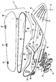
- the drawing shows an embodiment of the invention based on a perspective, exploded, schematic representation of the container of the silo vehicle.
- the silo vehicle consists in a known manner of a towing vehicle and an articulated container.
- the towing vehicle is usually a two-axle vehicle with a driver's cabin.
- the front end of the container 1 and the towing vehicle, not shown, are connected to one another in an articulated manner by means of a turntable, the geometric axis of the swivel joint extending essentially in the vertical direction or perpendicular to the roadway. It is shown schematically in the drawing and labeled 2.
- the rear region of the container 1 is supported on the roadway by means of an axle assembly 3, which is also only indicated schematically. As shown in the exemplary embodiment, it can have three parallel axes 4, 5 and 6, each axis being equipped with two wheels 7, 8.
- the container 1 is not supported directly on the axle assembly 3, but indirectly via a bowl-shaped receptacle 9. It consists in principle of an essentially flat bottom 10 and a circumferential side edge 11. According to the drawing, this is at least at its front and rear ends pulled up. This creates a front and a rear end element 12 and 13.
- the front end element can take the form of a slipper front part. It lies directly on the turntable and can partially form it. Longitudinal ribs 14, beads or the like. of the front End element 12 serve to stiffen it. This reinforcement is necessary because the force is introduced there when the container is being towed.
- both the shell-shaped receptacle 9 and the container 1 are made of fiber composite material, that is to say of a reinforced plastic. This is not only characterized by its resistance to the contents, but also by its high strength and low specific weight. The strength is about a factor of 5 higher than that of aluminum. In contrast, the specific weight is only half as large as that of aluminum. If one compares the production of this container with that of the prior art, one achieves a weight saving in this way, which can be in the order of 600 to 700 kg. The manufacturing costs and the material costs are also significantly lower.
- the bottom 10 of the cup-shaped receptacle 9 tapers not only at its front end, but also at its rear end according to the drawing. There, too, the side edge is raised and comparable to the heel part of a slipper.
- the rear area of the bowl-shaped receptacle 9 lies on a frame or the like. of the axle assembly 3 and is firmly connected.
- a box-like extension 16 can also be attached to the underside of the floor 10, in particular integrally formed thereon, which is preferably located in front of the axle assembly 3 in the forward direction of travel.
- the container 1 is provided with two so-called cones 18, 19. At the lower end of each cone there is a container outlet opening which corresponds to an outlet opening 17 of the bowl-shaped receptacle 9.
- a closure of a conventional type allows this container 1 to be emptied via the two container openings and the downstream outlet openings 17 of the receptacle 9.
- the rear outlet opening 17 of the exemplary embodiment can be placed in such a way that the material exits between the axle assembly 3 and the box-like extension 16.
- the subdivision of a container 1 into several cones has the advantage that one bulk goods despite the horizontal arrangement of the container 1 can drain.
- the cone wall must be selected so that it takes into account the normal slope angle of the bulk material.
- the container 1 preferably consists of two parts, namely the bowl-shaped upper part 20 and the likewise bowl-shaped lower part 21. If the cones 18 and 19 mentioned above or also further cones are formed on the latter, a constriction 22 is formed between adjacent cones. To be able to support such container 1 or its lower part 21 properly on the bowl-shaped receptacle 19 and also to ensure a favorable optical appearance, the two preferably parallel longitudinal parts of the peripheral side edge 11 are pulled up in a single constriction 22 approximately in the central region, so that a pair of ear-shaped support lugs 23 and 24 arise. In this way, smooth, continuous longitudinal surfaces of the unit consisting of container 1 and receptacle 9 are obtained, which gives an aerodynamic advantage and a pleasing appearance.
- the container 1 or its two halves or parts are also made of fiber composite material, the fiber-reinforced plastic material of the container and the receptacle 9 not necessarily having to be identical.
- the most important factor is the respective load and possibly also the resistance to the goods being transported.
- the container 1 is preferably divided approximately in a horizontal central plane, the upper part and the lower part of course not having to form exactly one half of the container in a strictly mathematical sense.
- the two facing peripheral edges 25 and 26 of the lower part 21 and the upper part 20 have the same shape.
- the two container halves are plugged together and are tightly and permanently connected to one another, for example by gluing. Therefore, the two circumferential edges 25, 26 are purchased.
- the bowl-shaped upper part 20 has the shape of a boat according to the drawing. Starting from the peripheral edge 25 or 26, the shells taper downwards or upwards. At least one manhole 27 is provided at the top of the bowl-shaped upper part 20. In the exemplary embodiment, three manholes are provided. You can merge into a small dome in a known manner and be provided with a closure.
- a transverse, approximately vertical support wall 28 can be attached to the bowl-shaped receptacle 9 between these support lugs, in particular integrally formed thereon. Above all, it serves as bracing. she can but can also be used to secure the position of the container 1 and / or to secure it.
- the outlet openings of the container 1 or of the container lower part 21 are designated 29 and, as said, they correspond to the outlet openings 17 of the bowl-shaped receptacle 9.
Landscapes
- Engineering & Computer Science (AREA)
- Health & Medical Sciences (AREA)
- Public Health (AREA)
- Transportation (AREA)
- Mechanical Engineering (AREA)
- Filling Or Emptying Of Bunkers, Hoppers, And Tanks (AREA)
- Filling Or Discharging Of Gas Storage Vessels (AREA)
- Air Transport Of Granular Materials (AREA)
Claims (15)
- Véhicule-silo comportant un réservoir (1) horizontal muni d'au moins un orifice de décharge (17, 29) et dont l'extrémité avant est montée sur un véhicule tracteur de manière rotative autour d'un axe géométrique (2) perpendiculaire par rapport à la chaussée, et dont la zone, de préférence, arrière du réservoir s'appuie, par l'intermédiaire d'un mécanisme sur essieux (3), sur la chaussée, caractérisé en ce que le réservoir (1) est fabriqué en un matériau composite renforcé par des fibres et inséré dans un logement (9) en forme de coque, également réalisé en un matériau composite renforcé par des fibres, dont l'extrémité avant est montée de manière rotative sur le véhicule tracteur et qui est posé sur le mécanisme à essieux.
- Véhicule selon la revendication 1, caractérisé en ce que le réservoir (1) est constitué d'une partie supérieure en forme de coque (20) et d'une partie inférieure en forme de coque (21), le plan de séparation (25, 26) entre ces deux parties se situant au voisinage de la section transversale horizontale la plus grande.
- Véhicule selon la revendication 2, caractérisé en ce que les bords (25, 26) de la partie supérieure (20) et de la partie inférieure (21) du réservoir se chevauchent.
- Véhicule selon la revendication 3, caractérisé en ce que la partie supérieure (20) et la partie inférieure (21) du réservoir sont assemblées mutuellement sans aucun débordement ni vers l'intérieur ni vers l'extérieur.
- Véhicule selon l'une quelconque des revendications 2 à 4, caractérisé en ce que la partie supérieure (20) et la partie inférieure (21) du réservoir sont assemblées mutuellement de manière étanche par collage, soudage ou par une méthode analogue.
- Véhicule selon au moins l'une des revendications 1 à 5, caractérisé en ce que les fibres de renfort du matériau composite sont alignées.
- Véhicule selon au moins l'une des revendications 1 à 6, caractérisé en ce que la partie inférieure (21) du réservoir en forme de coque présente au moins un ceinturage (22) en vue de la formation de cônes (18, 19), chacun des cônes (18, 19) présentant en bas un orifice de décharge (29) auquel est associé respectivement un orifice de décharge (17) du logement (9) en forme de coque.
- Véhicule selon la revendication 7, caractérisé en ce qu'à chaque ceinturage (22) de la partie inférieure (21) du réservoir, est associée une paire d'épaulements de renfort (23, 24) du logement (9), en forme d'oreilles, ces épaulements étant posés, voire moulés, sur les deux bords longitudinaux parallèles de la partie inférieure (21) du réservoir, et s'étendent à partir de leur bord longitudinal (11) vers le haut ou vers l'extérieur en haut.
- Véhicule selon la revendication 8, caractérisé par la présence d'une paroi de renfort (28) sensiblement verticale, s'étendant transversalement par rapport à l'axe longitudinal du logement (9) en forme de coque, entre les épaulements (23, 24) en forme d'oreilles de chaque paire.
- Véhicule selon l'une quelconque des revendications 2 à 9, caractérisé par la présence d'un fond sensiblement plat (10) du logement (9) en forme de coque, fond sur les extrémités avant et arrière duquel les bords latéraux (11) sont tirés vers le haut jusqu'au plan de séparation du réservoir (1), et forment de préférence chacun un élément terminal (12 et 13) qui s'amincit en direction de son extrémité.
- Véhicule selon la revendication 10, caractérisé en ce que l'élément terminal (12) avant présente la forme de la partie avant d'une pantoufle, et que le bord (11) tiré en hauteur est muni en cet endroit de gorges longitudinales, de nervures 14 ou d'éléments de renfort analogues.
- Véhicule selon la revendication 11, caractérisé en ce que l'élément terminal (13) arrière qui s'amincit en forme d'arc, est muni de gorges (15) s'étendant de bas en haut, de nervures ou d'éléments de renfort analogues.
- Véhicule selon l'une quelconque des revendications 10 à 12, caractérisé en ce que sur la face inférieure du fond (10) du logement (9), dans la région du mécanisme à essieux (3) ou avant celui-ci, se trouve un élément rajouté (16) du type caisson qui est monté sur le mécanisme à essieu (3) ou placé devant celui-ci.
- Véhicule selon l'une quelconque des revendications 1 à 13, caractérisé en ce que la construction du mécanisme à essieux (3) est modulaire.
- Véhicule selon au moins l'une des revendications 2 à 14, caractérisé par la présence d'au moins un trou d'homme intégré (27) situé en haut sur la partie supérieure (20) en forme de coque du réservoir (1).
Priority Applications (3)
| Application Number | Priority Date | Filing Date | Title |
|---|---|---|---|
| AT94113384T ATE160732T1 (de) | 1994-08-26 | 1994-08-26 | Silo-fahrzeug |
| EP94113384A EP0698526B1 (fr) | 1994-08-26 | 1994-08-26 | Véhicule-silo |
| DE59404732T DE59404732D1 (de) | 1994-08-26 | 1994-08-26 | Silo-Fahrzeug |
Applications Claiming Priority (1)
| Application Number | Priority Date | Filing Date | Title |
|---|---|---|---|
| EP94113384A EP0698526B1 (fr) | 1994-08-26 | 1994-08-26 | Véhicule-silo |
Publications (2)
| Publication Number | Publication Date |
|---|---|
| EP0698526A1 EP0698526A1 (fr) | 1996-02-28 |
| EP0698526B1 true EP0698526B1 (fr) | 1997-12-03 |
Family
ID=8216235
Family Applications (1)
| Application Number | Title | Priority Date | Filing Date |
|---|---|---|---|
| EP94113384A Expired - Lifetime EP0698526B1 (fr) | 1994-08-26 | 1994-08-26 | Véhicule-silo |
Country Status (3)
| Country | Link |
|---|---|
| EP (1) | EP0698526B1 (fr) |
| AT (1) | ATE160732T1 (fr) |
| DE (1) | DE59404732D1 (fr) |
Families Citing this family (5)
| Publication number | Priority date | Publication date | Assignee | Title |
|---|---|---|---|---|
| FR2943995B1 (fr) | 2009-04-03 | 2011-03-25 | Ets Magyar | Troncon en materiau composite pour vehicule citerne |
| FR2943960B1 (fr) | 2009-04-03 | 2011-03-25 | Ets Magyar | Vehicule citerne autoporte |
| DE102010008369A1 (de) * | 2010-02-17 | 2011-08-18 | Hermanns Silo GmbH, 51149 | Silofahrzeug |
| FR2978745B1 (fr) | 2011-08-01 | 2014-11-21 | Ets Magyar | Citerne autoportee en materiau composite et procede de realisation d’un corps de citerne en materiau composite |
| DE102012201784B4 (de) * | 2012-02-07 | 2019-07-04 | Sebastian Zunhammer | Tank aus Faserkunststoffverbundwerkstoff, ein Verfahren zu dessen Herstellung und ein Anhängerfahrzeug aufweisend einen derartigen Tank |
Family Cites Families (3)
| Publication number | Priority date | Publication date | Assignee | Title |
|---|---|---|---|---|
| CH558746A (de) * | 1973-05-28 | 1975-02-14 | Basler Stueckfaerberei Ag | Zylindrischer behaelter aus faserverstaerktem kunststoff und verfahren zu dessen herstellung. |
| GB2039980B (en) * | 1978-12-22 | 1982-10-06 | Moore Plastics Co Ltd | Bulk tanks |
| FR2578308B1 (fr) * | 1985-03-01 | 1988-07-01 | Robine Sa | Citerne frettee, notamment destinee au transport des fluides sous pression |
-
1994
- 1994-08-26 DE DE59404732T patent/DE59404732D1/de not_active Expired - Fee Related
- 1994-08-26 EP EP94113384A patent/EP0698526B1/fr not_active Expired - Lifetime
- 1994-08-26 AT AT94113384T patent/ATE160732T1/de not_active IP Right Cessation
Also Published As
| Publication number | Publication date |
|---|---|
| DE59404732D1 (de) | 1998-01-15 |
| ATE160732T1 (de) | 1997-12-15 |
| EP0698526A1 (fr) | 1996-02-28 |
Similar Documents
| Publication | Publication Date | Title |
|---|---|---|
| DE69720585T2 (de) | Lastbodenstruktur eines Kraftfahrzeuges | |
| DE19843025C1 (de) | Trennanordnung für eine selbsttragende Karosserie | |
| DE3875975T2 (de) | Aufbau eines wagenkastens fuer lastwagen. | |
| DE102008008146B4 (de) | Rahmen für ein batteriebetriebenes Flurförderzeug | |
| DE10016757A1 (de) | Mobiler Vorratsbehälter sowie Transportfahrzeug für einen solchen Behälter und Verfahren zu dessen Aufstellung | |
| DE602004004373T2 (de) | Sattelaufliegerrahmen und -radaufhängung | |
| DE3332919A1 (de) | Fahrzeugrahmen | |
| EP0698526B1 (fr) | Véhicule-silo | |
| DE2909350A1 (de) | Tankauto zum transport von fluessigen oder pulverfoermigen stoffen, insbesondere von oel | |
| DE102016111308B4 (de) | Fahrgestellanordnung und Landfahrzeug | |
| EP0193182B1 (fr) | Véhicules à ordures | |
| DE3114415A1 (de) | "aufbauendwand fuer personenkraftwagen" | |
| DE3808314C1 (fr) | ||
| DE19808123A1 (de) | Kippmulde | |
| DE1430694B2 (de) | Stuetzradanordnung fuer ein betonmischfahrzeug | |
| DE2510617A1 (de) | Grossraum-muellsammelbehaelter | |
| DE2150424C3 (de) | Abstützung für Fahrerhäuser von Schleppern und Baufahrzeugen mit einem quer über das Fahrzeug geführten Schutzrahmen oder Oberrollbügel | |
| WO1994018029A1 (fr) | Camion-citerne | |
| DE2450455A1 (de) | Lastkraftwagen mit einer mulde fuer schuettbares und/oder stueckiges ladegut | |
| DE3510291A1 (de) | Schuettgutcontainer fuer den strassentransport | |
| DE2014971A1 (de) | Kraftfahrzeug zum Transport eines Behälters | |
| EP1052163B1 (fr) | Remorque avec une carrosserie autoportante d'un métal léger | |
| DE7507663U (de) | Großraum-Müllsammelbe halter | |
| DE8527911U1 (de) | Behälter für fließfähiges Material | |
| DE945432C (de) | Motor- und Hinterradhaube fuer Motorroller |
Legal Events
| Date | Code | Title | Description |
|---|---|---|---|
| PUAI | Public reference made under article 153(3) epc to a published international application that has entered the european phase |
Free format text: ORIGINAL CODE: 0009012 |
|
| 17P | Request for examination filed |
Effective date: 19950701 |
|
| AK | Designated contracting states |
Kind code of ref document: A1 Designated state(s): AT BE DE FR GB IT NL |
|
| RIN1 | Information on inventor provided before grant (corrected) |
Inventor name: BETZMEIR, HELMUT, DIPL.-ING. Inventor name: MULLER, H.D., ING. Inventor name: GANTZER, PATRICK |
|
| 17Q | First examination report despatched |
Effective date: 19961002 |
|
| GRAG | Despatch of communication of intention to grant |
Free format text: ORIGINAL CODE: EPIDOS AGRA |
|
| GRAH | Despatch of communication of intention to grant a patent |
Free format text: ORIGINAL CODE: EPIDOS IGRA |
|
| GRAH | Despatch of communication of intention to grant a patent |
Free format text: ORIGINAL CODE: EPIDOS IGRA |
|
| GRAA | (expected) grant |
Free format text: ORIGINAL CODE: 0009210 |
|
| AK | Designated contracting states |
Kind code of ref document: B1 Designated state(s): AT BE DE FR GB IT NL |
|
| REF | Corresponds to: |
Ref document number: 160732 Country of ref document: AT Date of ref document: 19971215 Kind code of ref document: T |
|
| ITF | It: translation for a ep patent filed | ||
| GBT | Gb: translation of ep patent filed (gb section 77(6)(a)/1977) |
Effective date: 19971209 |
|
| REF | Corresponds to: |
Ref document number: 59404732 Country of ref document: DE Date of ref document: 19980115 |
|
| ET | Fr: translation filed | ||
| PLBE | No opposition filed within time limit |
Free format text: ORIGINAL CODE: 0009261 |
|
| STAA | Information on the status of an ep patent application or granted ep patent |
Free format text: STATUS: NO OPPOSITION FILED WITHIN TIME LIMIT |
|
| 26N | No opposition filed | ||
| REG | Reference to a national code |
Ref country code: GB Ref legal event code: IF02 |
|
| PGFP | Annual fee paid to national office [announced via postgrant information from national office to epo] |
Ref country code: FR Payment date: 20050819 Year of fee payment: 12 |
|
| PGFP | Annual fee paid to national office [announced via postgrant information from national office to epo] |
Ref country code: GB Payment date: 20060818 Year of fee payment: 13 |
|
| PGFP | Annual fee paid to national office [announced via postgrant information from national office to epo] |
Ref country code: NL Payment date: 20060821 Year of fee payment: 13 |
|
| PGFP | Annual fee paid to national office [announced via postgrant information from national office to epo] |
Ref country code: BE Payment date: 20060828 Year of fee payment: 13 Ref country code: AT Payment date: 20060828 Year of fee payment: 13 |
|
| PGFP | Annual fee paid to national office [announced via postgrant information from national office to epo] |
Ref country code: IT Payment date: 20060831 Year of fee payment: 13 |
|
| PGFP | Annual fee paid to national office [announced via postgrant information from national office to epo] |
Ref country code: DE Payment date: 20061020 Year of fee payment: 13 |
|
| BERE | Be: lapsed |
Owner name: *SPITZER EUROVRAC S.A.R.L. Effective date: 20070831 Owner name: *SPITZER SILO-FAHRZEUGWERKE G.M.B.H. & CO. K.G. Effective date: 20070831 |
|
| GBPC | Gb: european patent ceased through non-payment of renewal fee |
Effective date: 20070826 |
|
| PG25 | Lapsed in a contracting state [announced via postgrant information from national office to epo] |
Ref country code: NL Free format text: LAPSE BECAUSE OF NON-PAYMENT OF DUE FEES Effective date: 20080301 |
|
| NLV4 | Nl: lapsed or anulled due to non-payment of the annual fee |
Effective date: 20080301 |
|
| PG25 | Lapsed in a contracting state [announced via postgrant information from national office to epo] |
Ref country code: AT Free format text: LAPSE BECAUSE OF NON-PAYMENT OF DUE FEES Effective date: 20070826 |
|
| REG | Reference to a national code |
Ref country code: FR Ref legal event code: ST Effective date: 20080430 |
|
| PG25 | Lapsed in a contracting state [announced via postgrant information from national office to epo] |
Ref country code: DE Free format text: LAPSE BECAUSE OF NON-PAYMENT OF DUE FEES Effective date: 20080301 |
|
| PG25 | Lapsed in a contracting state [announced via postgrant information from national office to epo] |
Ref country code: BE Free format text: LAPSE BECAUSE OF NON-PAYMENT OF DUE FEES Effective date: 20070831 |
|
| PG25 | Lapsed in a contracting state [announced via postgrant information from national office to epo] |
Ref country code: FR Free format text: LAPSE BECAUSE OF NON-PAYMENT OF DUE FEES Effective date: 20070831 |
|
| PG25 | Lapsed in a contracting state [announced via postgrant information from national office to epo] |
Ref country code: GB Free format text: LAPSE BECAUSE OF NON-PAYMENT OF DUE FEES Effective date: 20070826 |
|
| PG25 | Lapsed in a contracting state [announced via postgrant information from national office to epo] |
Ref country code: FR Free format text: LAPSE BECAUSE OF NON-PAYMENT OF DUE FEES Effective date: 20060831 |
|
| PG25 | Lapsed in a contracting state [announced via postgrant information from national office to epo] |
Ref country code: IT Free format text: LAPSE BECAUSE OF NON-PAYMENT OF DUE FEES Effective date: 20070826 |