EP0698557A1 - Recipient en matiere plastique pour liquides - Google Patents
Recipient en matiere plastique pour liquides Download PDFInfo
- Publication number
- EP0698557A1 EP0698557A1 EP95923109A EP95923109A EP0698557A1 EP 0698557 A1 EP0698557 A1 EP 0698557A1 EP 95923109 A EP95923109 A EP 95923109A EP 95923109 A EP95923109 A EP 95923109A EP 0698557 A1 EP0698557 A1 EP 0698557A1
- Authority
- EP
- European Patent Office
- Prior art keywords
- bottles
- bottle
- body portion
- side faces
- piled
- Prior art date
- Legal status (The legal status is an assumption and is not a legal conclusion. Google has not performed a legal analysis and makes no representation as to the accuracy of the status listed.)
- Withdrawn
Links
- 239000004033 plastic Substances 0.000 title claims abstract description 39
- 229920003023 plastic Polymers 0.000 title claims abstract description 39
- 239000007788 liquid Substances 0.000 title claims abstract description 14
- 230000000694 effects Effects 0.000 description 6
- 238000006073 displacement reaction Methods 0.000 description 4
- 230000002459 sustained effect Effects 0.000 description 4
- XLYOFNOQVPJJNP-UHFFFAOYSA-N water Substances O XLYOFNOQVPJJNP-UHFFFAOYSA-N 0.000 description 4
- 235000011389 fruit/vegetable juice Nutrition 0.000 description 3
- 229910052500 inorganic mineral Inorganic materials 0.000 description 3
- 239000011707 mineral Substances 0.000 description 3
- 229920000139 polyethylene terephthalate Polymers 0.000 description 3
- 239000005020 polyethylene terephthalate Substances 0.000 description 3
- 238000010586 diagram Methods 0.000 description 2
- 238000012856 packing Methods 0.000 description 2
- -1 PolyEthylene Terephthalate Polymers 0.000 description 1
- 239000008186 active pharmaceutical agent Substances 0.000 description 1
- 238000005452 bending Methods 0.000 description 1
- 230000006835 compression Effects 0.000 description 1
- 238000007906 compression Methods 0.000 description 1
- 238000010413 gardening Methods 0.000 description 1
- 230000005484 gravity Effects 0.000 description 1
- 239000000463 material Substances 0.000 description 1
- 238000012986 modification Methods 0.000 description 1
- 230000004048 modification Effects 0.000 description 1
- 239000004576 sand Substances 0.000 description 1
- 238000007493 shaping process Methods 0.000 description 1
- 229920003002 synthetic resin Polymers 0.000 description 1
- 239000000057 synthetic resin Substances 0.000 description 1
Images


Classifications
-
- B—PERFORMING OPERATIONS; TRANSPORTING
- B65—CONVEYING; PACKING; STORING; HANDLING THIN OR FILAMENTARY MATERIAL
- B65D—CONTAINERS FOR STORAGE OR TRANSPORT OF ARTICLES OR MATERIALS, e.g. BAGS, BARRELS, BOTTLES, BOXES, CANS, CARTONS, CRATES, DRUMS, JARS, TANKS, HOPPERS, FORWARDING CONTAINERS; ACCESSORIES, CLOSURES, OR FITTINGS THEREFOR; PACKAGING ELEMENTS; PACKAGES
- B65D21/00—Nestable, stackable or joinable containers; Containers of variable capacity
- B65D21/02—Containers specially shaped, or provided with fittings or attachments, to facilitate nesting, stacking, or joining together
- B65D21/0201—Containers specially shaped, or provided with fittings or attachments, to facilitate nesting, stacking, or joining together stackable or joined together side-by-side
-
- B—PERFORMING OPERATIONS; TRANSPORTING
- B65—CONVEYING; PACKING; STORING; HANDLING THIN OR FILAMENTARY MATERIAL
- B65D—CONTAINERS FOR STORAGE OR TRANSPORT OF ARTICLES OR MATERIALS, e.g. BAGS, BARRELS, BOTTLES, BOXES, CANS, CARTONS, CRATES, DRUMS, JARS, TANKS, HOPPERS, FORWARDING CONTAINERS; ACCESSORIES, CLOSURES, OR FITTINGS THEREFOR; PACKAGING ELEMENTS; PACKAGES
- B65D21/00—Nestable, stackable or joinable containers; Containers of variable capacity
- B65D21/02—Containers specially shaped, or provided with fittings or attachments, to facilitate nesting, stacking, or joining together
- B65D21/0209—Containers specially shaped, or provided with fittings or attachments, to facilitate nesting, stacking, or joining together stackable or joined together one-upon-the-other in the upright or upside-down position
- B65D21/023—Closed containers provided with local cooperating elements in the top and bottom surfaces, e.g. projection and recess
- B65D21/0231—Bottles, canisters or jars whereby the neck or handle project into a cooperating cavity in the bottom
Definitions
- the present invention relates to a plastic bottle for containing mineral water, juice, etc.
- the present invention is accomplished for solving the above described problems, the first object of which is to provide, based on the knowledge of structural mechanics, a bottle that is designed to prevent the lower bottle from buckling or deforming even under the weight of several filled bottles put thereon when they are piled up vertically.
- the second object of the present invention is to make a bottle capable of being aligned or built up in a stable state by improving the bandability and combinability of the bottles contacting at the side faces.
- a plastic bottle for containing liquid comprising:
- the mouth and the cap of the lower bottle are wholly admitted in the cavity formed at the bottom of the upper bottle, so that the storage efficiency is very high in case a number of the present bottles are contained in a large transport box. Furthermore, in that case, the weight of the upper bottle is sustained by the lower bottle solely at the four vertexes of the substantially rectangular prism because the cavity and the cap do not contact with each other, so that a number of bottles can be piled up vertically in a stable state without causing deformation or buckling of lower bottles. The reason is explained as follows.
- one of the possible ideas to prevent a displacement between the two piled-up plastic bottles B h and B l is to make the two bottles contact at the top of the cap P a , at the side of the cap P b and at the shoulder of the body portion P c , where the weight of the upper bottle B h (and the liquid contained therein) is sustained mainly by the top of the cap P a which is normally strong. Since, however, the sustaining base area is very small in this case, the center of gravity of the upper bottle B h easily comes out of the base area and the upper bottle B h falls down even with a slight displacement thereof.
- the shoulder S ld (including the part of the shoulder that is not contacting) of the lowest bottle may buckle and the upper bottle also falls down.
- the contact planes formed at the bottom of the upper plastic bottle contact the horizontal planes formed in the upper portion of the lower plastic bottle.
- the cavity formed at the bottom of the upper plastic bottle does not contact the mouth and the cap put thereon of the lower plastic bottle, therefore the weight of the upper plastic bottle (and the liquid contained therein) is not exerted on the mouth of the lower plastic bottle, but is mainly exerted on the upper four corners of the lower plastic bottle.
- FIG. 7(b) illustrates that the diagonal D R of the rectangle R and the diagonal D S of the square S are longer than the diameter D C of the circle C when the rectangle R, the square S and the circle C have the same area.
- the plastic bottle of the present invention has a longer legspan for sustaining the weight of the plastic bottle (and the liquid contained therein) than that of a circular cylindrical plastic bottle with the same height and the same cross-sectional area (i.e. with the same volume). Therefore, when being piled up, the plastic bottles do not buckle and can be piled up in multitude in a stable state, as shown in the frame diagram of Fig. 7(d).
- the periphery of the mouth of a plastic bottle needs to be inclined to let out all the liquid contained therein completely.
- the weight W of the upper bottle B h (and the liquid contained therein) exerts a horizontal component force C m and a vertical component force S h on the wall of the lower plastic bottle B l , as shown in Fig. 7(c).
- the wall members of a bottle made of plastic, such as PET (PolyEthylene Terephthalate) generally have sufficient strength against compression and tension due to horizontal force, while they are weak against bending moment or shear due to vertical force, and even a comparatively small load (i.e.
- the loading points on the lower bottle are located at the vertexes of the rectangle (or the square) which are the most advantageous points in respect of the strength and stability, the weight of the upper bottle is sustained by the beams (edges) in the beam structure of the substantially rectangular prism of the lower bottle, as shown in Fig. 7(d). Therefore, the lower bottle can sustain the weight without deforming even when a number of filled bottles are piled up thereon.
- maximum effect is obtained in case that the cross section is square, but sufficient effect can also be obtained with rectangular cross section if the rectangle is not far from a square.
- the object can be accomplished by forming elevations on adjoining two side faces and depressions corresponding to the elevations on the other adjoining two side faces of the four side faces of the body portion.
- the horizontal cross section needs to be substantially square.
- the shop clerk can align the bottles neatly without difficulty because the mutual position of the neighboring bottles are fixed by fitting the elevation and the depression of the neighboring bottles. Since the elevations are formed on adjoining two side faces, all the bottles are aligned with their direction being the same when they are aligned two-dimensionally, which facilitates automatic aligning. If the elevations are formed on opposing two side faces and the depressions are formed on the other opposing two side faces, on the contrary, directions of the bottles must differ alternately by 90°.
- a constriction is formed in the body portion dividing the body portion into the upper body portion and the lower body portion, and the elevations and the depressions on the adjoining faces are formed at least in one of the upper body portion and the lower body portion.
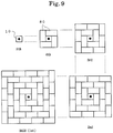
- two plastic bottles can be bundled into a unit by fitting a band in the constriction. Since the cross section of the unit is a rectangle with the side ratio of 2:1, the units can be used to build a variety of structures just like dominos or toy blocks.
- the plastic bottles of the present invention can be used for toy blocks, as well as for liquid transportation, because they are easily combined together. It is further possible to use them as gardening blocks or weight blocks by filling them with sand or water.
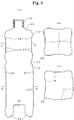
- Fig. 1(a) is a front view of a bottle of the present embodiment (a rear view is the mirror image thereof), and (b) is a right side view (a left side view is the mirror image thereof).
- Fig. 2(a) is a top view, (b) is a cross-sectional view as seen on the line A-A' of Fig. 1, and (c) is a bottom view.
- Fig. 3(a) is a cut end view on the line B-B' of Fig. 2(a), (b) is a cut end view on the line C-C' of Fig. 3(a), and (c) is a cut end view on the line D-D' of Fig.
- the bottle 10 of the present embodiment has a substantially square cross section. Separated by a constriction 14 at the center, the upper portion 13 has depressions 16 on all of its four side faces, and the lower portion 15 has elevations 17 on adjoining two side faces and depressions 18 on the other adjoining two side faces.
- Synthetic resin with a good workability (such as PET) is preferred as the material of the bottle 10. Further, transparency is preferred when the bottle is used to contain mineral water, juice, etc.
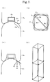
- Fig. 4 shows a cut end view of four bottles piled up laterally and vertically cut by a vertical center plane.
- the bottles 10 of the present embodiment have a very high storage efficiency.
- the storage efficiency is improved by 30% compared to conventional cylindrical bottles having no cavity at the bottom.
- Fig. 6(a) illustrates the detail loading condition of two bottles 10 of the present embodiment piled up vertically.
- the upper bottle 10H and the lower bottle 10L of the present embodiment contact neither at the cap 11 nor at the inclined surface 12, and a small gap 27 exists between the two bottles. Therefore, the weight of the upper bottle 10H is sustained by the four sides of the cross-sectional square of the upper portion 13 and the four sides of the lower portion 15, where the two bottles 10H and 10L contact. Since, however, each side is relatively weaker at the center than near the corners, it is the corners of the square that mainly sustain the weight of the upper bottle 10H.
- both the upper portion 13 and the lower portion 15 have chamfers 22 at their corners, from which it results that they have a sufficient strength against vertical loading, and the lower bottle 10 can sustain weight without deforming even when a number of bottles 10 are piled up thereon.
- the numeral 25 denotes a loading plane formed at a corner of the lower bottle 10L
- the numeral 26 denotes a contact plane of the upper bottle 10H.
- a conventional bottle as shown in Fig. 7(a) which contacts the upper bottle at its shoulder can sustain a weight of about 1.5 to 10kgf at most, while the bottle 10 of the present embodiment can sustain a weight up to 30kgf.
- the bottom square of the lower portion 15 have their sides slightly arched at the center 28 to prevent the upper and lower bottles from contacting there, whereby the corner loading is assured.
- the body portion is divided by a constriction 14 into the upper portion 13 and the lower portion 15, and the upper portion 13 has depressions 16 on all of its four side faces, which helps easy holding of the bottle 10.
- the lower portion 15 has depressions on all of its four side faces while the upper portion 13 has elevations on two side faces and depressions on two side faces.
- the constriction 14 itself can be used for bundling the bottles 10 with a band or the like after the bottles are aligned laterally.
- Fig. 9 and Fig. 10 show two examples.
- the bottle can be held securely because a number of horizontal ridges or ditches 19 are formed on the surface of the elevation 17 and the depression 16 and 18 so that it is prevented from slipping off the hand when held. These ridges or ditches 19 also help preventing the bottles from displacing from each other when the bottles 10 are laterally packed or when the bottles 10 are laid down and piled up. In the present bottle 10, in detail description, ridges 19 are formed on the depressions 16 and 18, and ditches 19 are formed on the elevations 17 (Fig. 3).
- the cross section of the present bottle is made substantially square, so that the storage efficiency when contained in a large transport box generally increases, and an automatic packing is facilitated.
- the elevations are formed on adjoining two side faces, all the bottles are aligned with their direction being the same when they are aligned two-dimensionally, which facilitates automatic packing of the bottles in large transport boxes. If the elevations are formed on opposing two side faces and the depressions are formed on the other opposing two side faces, directions of the bottles must differ alternately by 90°. Furthermore, as described above, piling up of the laid bottles (Fig. 6(c)) is also facilitated.
- the bottle It is possible to design the bottle to have elevations on two opposing side faces and depressions on the other two opposing side faces, as shown in Fig. 5, if a special display effect is aimed where the labels appear alternately, or if easy bottle holding is regarded most. However, the above described facilities in displaying and piling work may be sacrificed a little thereby.
- Fig. 1 (a) A front view, and (b) a right side view, of the bottle in one of the embodiments of the present invention.
- Fig. 2 (a) A top view, (b) a cross-sectional view seen on the line A-A' of Fig. 1 and (c) a bottom view, of the bottle of the embodiment.
- Fig. 3 (a) A cut end view on the line B-B' of Fig. 2(a), (b) a cut end view on the line C-C' of Fig. 3(a) and (c) a cut end view on the line D-D' of Fig. 3(a).
- Fig. 4 A cut end view on the vertical center plane of the bottles of the embodiment in a laterally and vertically piled-up state.
- Fig. 5 (a) A cut end view on the vertical center plane, (b) a cut end view of the upper portion and (c) a cut end view of the lower portion, in another embodiment of the present invention.
- Fig. 6 (a) A detail view of a vertical cross section of the bottles according to the present invention being piled up, (b) a side view showing a modification of the bottom, and (c) a front view of the bottles in the state of being laid down and piled up.
- FIG. 7 Figures illustrating the effects of the present invention.
- Fig. 8 A side view of a unit composed of two plastic bottles of the embodiment.
- Fig. 9 A plan view of a first example of a build-up structure of the above unit.
- Fig. 10 A plan view of a second example of a build-up structure of the above unit.
Landscapes
- Engineering & Computer Science (AREA)
- Mechanical Engineering (AREA)
- Stackable Containers (AREA)
Applications Claiming Priority (5)
| Application Number | Priority Date | Filing Date | Title |
|---|---|---|---|
| JP3799/94U | 1994-03-18 | ||
| JP1994003799U JP3002152U (ja) | 1994-03-18 | 1994-03-18 | 液体用容器 |
| JP18403894A JPH0826240A (ja) | 1994-07-12 | 1994-07-12 | 液体用プラスチック容器 |
| JP184038/94 | 1994-07-12 | ||
| PCT/JP1995/000448 WO1995025666A1 (fr) | 1994-03-18 | 1995-03-16 | Recipient en matiere plastique pour liquides |
Publications (1)
| Publication Number | Publication Date |
|---|---|
| EP0698557A1 true EP0698557A1 (fr) | 1996-02-28 |
Family
ID=26337440
Family Applications (1)
| Application Number | Title | Priority Date | Filing Date |
|---|---|---|---|
| EP95923109A Withdrawn EP0698557A1 (fr) | 1994-03-18 | 1995-03-16 | Recipient en matiere plastique pour liquides |
Country Status (2)
| Country | Link |
|---|---|
| EP (1) | EP0698557A1 (fr) |
| WO (1) | WO1995025666A1 (fr) |
Cited By (7)
| Publication number | Priority date | Publication date | Assignee | Title |
|---|---|---|---|---|
| DE29600051U1 (de) * | 1996-01-03 | 1996-02-29 | Thielen, Hans Jürgen, 45307 Essen | Mehreckige Flasche zur Aufnahme von Flüssigkeiten o.dgl. fließfähigen Materialien |
| GB2316384A (en) * | 1996-08-23 | 1998-02-25 | Ahmed Rashidbigi | Containers and assemblies of containers |
| EP0857664A1 (fr) * | 1997-02-07 | 1998-08-12 | Mirta Mabel Fasci | Récipient modulaire et interconnectable à usages multiples |
| EP0842859A3 (fr) * | 1996-11-15 | 1998-08-26 | Meloni Vini S.r.l | Bouteille en matière plastique et procédé de sa fabrication et conditionnement |
| RU2169111C1 (ru) * | 2000-06-16 | 2001-06-20 | Белявский Сергей Борисович | Тара-конструктор |
| WO2013088006A1 (fr) | 2011-12-12 | 2013-06-20 | Sidel Participations | Récipient empilable comprenant un fond voûté à large surface de contact |
| FR3139322A1 (fr) | 2022-09-07 | 2024-03-08 | Sidel Participations | Récipient pressurisé à épaule et fond déformables |
Families Citing this family (1)
| Publication number | Priority date | Publication date | Assignee | Title |
|---|---|---|---|---|
| EP1740473A4 (fr) * | 2004-04-29 | 2007-11-21 | Plastipak Packaging Inc | Contenant en plastique empilable |
Family Cites Families (4)
| Publication number | Priority date | Publication date | Assignee | Title |
|---|---|---|---|---|
| JPS5859716U (ja) * | 1981-10-14 | 1983-04-22 | 横溝 和弘 | 積畳保管用容器 |
| JPS5922730U (ja) * | 1982-08-02 | 1984-02-13 | 大日本印刷株式会社 | ジヨイント付きボトル |
| JPS6197122U (fr) * | 1984-11-28 | 1986-06-21 | ||
| JPH01161428U (fr) * | 1987-12-18 | 1989-11-09 |
-
1995
- 1995-03-16 WO PCT/JP1995/000448 patent/WO1995025666A1/fr not_active Ceased
- 1995-03-16 EP EP95923109A patent/EP0698557A1/fr not_active Withdrawn
Non-Patent Citations (1)
| Title |
|---|
| See references of WO9525666A1 * |
Cited By (9)
| Publication number | Priority date | Publication date | Assignee | Title |
|---|---|---|---|---|
| DE29600051U1 (de) * | 1996-01-03 | 1996-02-29 | Thielen, Hans Jürgen, 45307 Essen | Mehreckige Flasche zur Aufnahme von Flüssigkeiten o.dgl. fließfähigen Materialien |
| GB2316384A (en) * | 1996-08-23 | 1998-02-25 | Ahmed Rashidbigi | Containers and assemblies of containers |
| GB2316384B (en) * | 1996-08-23 | 2000-08-30 | Ahmed Rashidbigi | Containers and assemblies of containers |
| EP0842859A3 (fr) * | 1996-11-15 | 1998-08-26 | Meloni Vini S.r.l | Bouteille en matière plastique et procédé de sa fabrication et conditionnement |
| EP0857664A1 (fr) * | 1997-02-07 | 1998-08-12 | Mirta Mabel Fasci | Récipient modulaire et interconnectable à usages multiples |
| RU2169111C1 (ru) * | 2000-06-16 | 2001-06-20 | Белявский Сергей Борисович | Тара-конструктор |
| WO2013088006A1 (fr) | 2011-12-12 | 2013-06-20 | Sidel Participations | Récipient empilable comprenant un fond voûté à large surface de contact |
| FR3139322A1 (fr) | 2022-09-07 | 2024-03-08 | Sidel Participations | Récipient pressurisé à épaule et fond déformables |
| WO2024052068A1 (fr) | 2022-09-07 | 2024-03-14 | Sidel Participations | Récipient pressurisé à épaule et fond déformables |
Also Published As
| Publication number | Publication date |
|---|---|
| WO1995025666A1 (fr) | 1995-09-28 |
Similar Documents
| Publication | Publication Date | Title |
|---|---|---|
| JP2820244B2 (ja) | 積重ね可能の浅い瓶ケース | |
| US7093715B1 (en) | Nestable can tray with contoured wall structure | |
| US4944400A (en) | Self-supporting storage, shipping and display assembly | |
| US5031761A (en) | Reusable case for beverage bottles | |
| US5769003A (en) | Keg pallet | |
| US4643314A (en) | Container construction | |
| JP2527721B2 (ja) | 積み重ね可能の矩形枠箱 | |
| JP3081249B2 (ja) | 積み重ね可能な深さの浅いボトルケース | |
| US3214052A (en) | Bottle construction | |
| US5002199A (en) | Stackable bottle | |
| SK103096A3 (en) | Crate for bottles | |
| MXPA01012482A (es) | Caja de baja profundidad apilable con estructura de mango. | |
| EP0698557A1 (fr) | Recipient en matiere plastique pour liquides | |
| US7114626B2 (en) | Synthetic resin container having a rectangular tubular shape | |
| MX2012001884A (es) | Un contenedor y una estructura incluyendo el contenedor como elemento de construcción. | |
| KR20210000685U (ko) | 곡물 적재함 | |
| US2330982A (en) | Carboy crate | |
| JP4986200B2 (ja) | ボトル用トレー | |
| CN215852466U (zh) | 一种防倾倒的堆码桶 | |
| EP0304224A2 (fr) | Caisses permettant leur empilement interverrouillé | |
| EP0758612A1 (fr) | Récipient emboîtable et empilable | |
| US6082542A (en) | Full-depth nestable crate | |
| JPH0826240A (ja) | 液体用プラスチック容器 | |
| CN223920083U (zh) | 箱体及内置盒体 | |
| JPH0711539U (ja) | 容 器 |
Legal Events
| Date | Code | Title | Description |
|---|---|---|---|
| PUAI | Public reference made under article 153(3) epc to a published international application that has entered the european phase |
Free format text: ORIGINAL CODE: 0009012 |
|
| AK | Designated contracting states |
Kind code of ref document: A1 Designated state(s): FR IT |
|
| 17P | Request for examination filed |
Effective date: 19960411 |
|
| STAA | Information on the status of an ep patent application or granted ep patent |
Free format text: STATUS: THE APPLICATION HAS BEEN WITHDRAWN |
|
| 18W | Application withdrawn |
Withdrawal date: 19980421 |