EP0698582A2 - Procédé de fabrication d'une fibre pour compenser la dispersion - Google Patents
Procédé de fabrication d'une fibre pour compenser la dispersion Download PDFInfo
- Publication number
- EP0698582A2 EP0698582A2 EP95113381A EP95113381A EP0698582A2 EP 0698582 A2 EP0698582 A2 EP 0698582A2 EP 95113381 A EP95113381 A EP 95113381A EP 95113381 A EP95113381 A EP 95113381A EP 0698582 A2 EP0698582 A2 EP 0698582A2
- Authority
- EP
- European Patent Office
- Prior art keywords
- optical fiber
- core
- cladding
- preform
- fiber
- Prior art date
- Legal status (The legal status is an assumption and is not a legal conclusion. Google has not performed a legal analysis and makes no representation as to the accuracy of the status listed.)
- Granted
Links
- 239000000835 fiber Substances 0.000 title claims abstract description 71
- 238000004519 manufacturing process Methods 0.000 title claims abstract description 18
- 239000006185 dispersion Substances 0.000 title claims description 74
- 239000013307 optical fiber Substances 0.000 claims abstract description 144
- 238000005253 cladding Methods 0.000 claims description 52
- 230000010287 polarization Effects 0.000 claims description 28
- YBMRDBCBODYGJE-UHFFFAOYSA-N germanium dioxide Chemical compound O=[Ge]=O YBMRDBCBODYGJE-UHFFFAOYSA-N 0.000 claims description 26
- 238000000034 method Methods 0.000 claims description 25
- VYPSYNLAJGMNEJ-UHFFFAOYSA-N Silicium dioxide Chemical compound O=[Si]=O VYPSYNLAJGMNEJ-UHFFFAOYSA-N 0.000 claims description 21
- 230000005540 biological transmission Effects 0.000 claims description 20
- 239000000463 material Substances 0.000 claims description 10
- 230000003287 optical effect Effects 0.000 claims description 8
- KLZUFWVZNOTSEM-UHFFFAOYSA-K Aluminium flouride Chemical compound F[Al](F)F KLZUFWVZNOTSEM-UHFFFAOYSA-K 0.000 claims description 6
- 229910004504 HfF4 Inorganic materials 0.000 claims description 3
- 229910007998 ZrF4 Inorganic materials 0.000 claims description 3
- 239000000377 silicon dioxide Substances 0.000 claims description 3
- OMQSJNWFFJOIMO-UHFFFAOYSA-J zirconium tetrafluoride Chemical compound F[Zr](F)(F)F OMQSJNWFFJOIMO-UHFFFAOYSA-J 0.000 claims description 3
- 239000011162 core material Substances 0.000 description 63
- OKTJSMMVPCPJKN-UHFFFAOYSA-N Carbon Chemical compound [C] OKTJSMMVPCPJKN-UHFFFAOYSA-N 0.000 description 20
- 229910052799 carbon Inorganic materials 0.000 description 20
- 238000005259 measurement Methods 0.000 description 15
- 239000011347 resin Substances 0.000 description 15
- 229920005989 resin Polymers 0.000 description 15
- 238000002474 experimental method Methods 0.000 description 6
- HEDRZPFGACZZDS-UHFFFAOYSA-N Chloroform Chemical compound ClC(Cl)Cl HEDRZPFGACZZDS-UHFFFAOYSA-N 0.000 description 4
- 239000002019 doping agent Substances 0.000 description 4
- 239000005383 fluoride glass Substances 0.000 description 4
- 238000005452 bending Methods 0.000 description 3
- 230000007423 decrease Effects 0.000 description 3
- 238000012986 modification Methods 0.000 description 3
- 230000004048 modification Effects 0.000 description 3
- PXGOKWXKJXAPGV-UHFFFAOYSA-N Fluorine Chemical compound FF PXGOKWXKJXAPGV-UHFFFAOYSA-N 0.000 description 2
- 239000011248 coating agent Substances 0.000 description 2
- 238000000576 coating method Methods 0.000 description 2
- 230000003247 decreasing effect Effects 0.000 description 2
- 229910052731 fluorine Inorganic materials 0.000 description 2
- 239000011737 fluorine Substances 0.000 description 2
- 238000010438 heat treatment Methods 0.000 description 2
- 239000007788 liquid Substances 0.000 description 2
- 238000005229 chemical vapour deposition Methods 0.000 description 1
- 238000000151 deposition Methods 0.000 description 1
- 238000010586 diagram Methods 0.000 description 1
- 230000000694 effects Effects 0.000 description 1
- 239000011521 glass Substances 0.000 description 1
- 239000003365 glass fiber Substances 0.000 description 1
- 239000000075 oxide glass Substances 0.000 description 1
- 230000001902 propagating effect Effects 0.000 description 1
- 230000008054 signal transmission Effects 0.000 description 1
- 235000012239 silicon dioxide Nutrition 0.000 description 1
- 239000012808 vapor phase Substances 0.000 description 1
- 238000001947 vapour-phase growth Methods 0.000 description 1
Images







Classifications
-
- G—PHYSICS
- G02—OPTICS
- G02B—OPTICAL ELEMENTS, SYSTEMS OR APPARATUS
- G02B6/00—Light guides; Structural details of arrangements comprising light guides and other optical elements, e.g. couplings
- G02B6/02—Optical fibres with cladding with or without a coating
- G02B6/02214—Optical fibres with cladding with or without a coating tailored to obtain the desired dispersion, e.g. dispersion shifted, dispersion flattened
- G02B6/02219—Characterised by the wavelength dispersion properties in the silica low loss window around 1550 nm, i.e. S, C, L and U bands from 1460-1675 nm
- G02B6/02252—Negative dispersion fibres at 1550 nm
- G02B6/02261—Dispersion compensating fibres, i.e. for compensating positive dispersion of other fibres
-
- C—CHEMISTRY; METALLURGY
- C03—GLASS; MINERAL OR SLAG WOOL
- C03B—MANUFACTURE, SHAPING, OR SUPPLEMENTARY PROCESSES
- C03B37/00—Manufacture or treatment of flakes, fibres, or filaments from softened glass, minerals, or slags
- C03B37/01—Manufacture of glass fibres or filaments
- C03B37/02—Manufacture of glass fibres or filaments by drawing or extruding, e.g. direct drawing of molten glass from nozzles; Cooling fins therefor
- C03B37/025—Manufacture of glass fibres or filaments by drawing or extruding, e.g. direct drawing of molten glass from nozzles; Cooling fins therefor from reheated softened tubes, rods, fibres or filaments, e.g. drawing fibres from preforms
- C03B37/027—Fibres composed of different sorts of glass, e.g. glass optical fibres
- C03B37/02745—Fibres having rotational spin around the central longitudinal axis, e.g. alternating +/- spin to reduce polarisation mode dispersion
-
- C—CHEMISTRY; METALLURGY
- C03—GLASS; MINERAL OR SLAG WOOL
- C03C—CHEMICAL COMPOSITION OF GLASSES, GLAZES OR VITREOUS ENAMELS; SURFACE TREATMENT OF GLASS; SURFACE TREATMENT OF FIBRES OR FILAMENTS MADE FROM GLASS, MINERALS OR SLAGS; JOINING GLASS TO GLASS OR OTHER MATERIALS
- C03C13/00—Fibre or filament compositions
- C03C13/04—Fibre optics, e.g. core and clad fibre compositions
- C03C13/045—Silica-containing oxide glass compositions
-
- G—PHYSICS
- G02—OPTICS
- G02B—OPTICAL ELEMENTS, SYSTEMS OR APPARATUS
- G02B6/00—Light guides; Structural details of arrangements comprising light guides and other optical elements, e.g. couplings
- G02B6/02—Optical fibres with cladding with or without a coating
- G02B6/02214—Optical fibres with cladding with or without a coating tailored to obtain the desired dispersion, e.g. dispersion shifted, dispersion flattened
- G02B6/02285—Characterised by the polarisation mode dispersion [PMD] properties, e.g. for minimising PMD
-
- G—PHYSICS
- G02—OPTICS
- G02B—OPTICAL ELEMENTS, SYSTEMS OR APPARATUS
- G02B6/00—Light guides; Structural details of arrangements comprising light guides and other optical elements, e.g. couplings
- G02B6/02—Optical fibres with cladding with or without a coating
- G02B6/036—Optical fibres with cladding with or without a coating core or cladding comprising multiple layers
- G02B6/03605—Highest refractive index not on central axis
- G02B6/03611—Highest index adjacent to central axis region, e.g. annular core, coaxial ring, centreline depression affecting waveguiding
-
- G—PHYSICS
- G02—OPTICS
- G02B—OPTICAL ELEMENTS, SYSTEMS OR APPARATUS
- G02B6/00—Light guides; Structural details of arrangements comprising light guides and other optical elements, e.g. couplings
- G02B6/02—Optical fibres with cladding with or without a coating
- G02B6/036—Optical fibres with cladding with or without a coating core or cladding comprising multiple layers
- G02B6/03616—Optical fibres characterised both by the number of different refractive index layers around the central core segment, i.e. around the innermost high index core layer, and their relative refractive index difference
- G02B6/03638—Optical fibres characterised both by the number of different refractive index layers around the central core segment, i.e. around the innermost high index core layer, and their relative refractive index difference having 3 layers only
- G02B6/0365—Optical fibres characterised both by the number of different refractive index layers around the central core segment, i.e. around the innermost high index core layer, and their relative refractive index difference having 3 layers only arranged - - +
-
- G—PHYSICS
- G02—OPTICS
- G02B—OPTICAL ELEMENTS, SYSTEMS OR APPARATUS
- G02B6/00—Light guides; Structural details of arrangements comprising light guides and other optical elements, e.g. couplings
- G02B6/02—Optical fibres with cladding with or without a coating
- G02B6/036—Optical fibres with cladding with or without a coating core or cladding comprising multiple layers
- G02B6/03616—Optical fibres characterised both by the number of different refractive index layers around the central core segment, i.e. around the innermost high index core layer, and their relative refractive index difference
- G02B6/03661—Optical fibres characterised both by the number of different refractive index layers around the central core segment, i.e. around the innermost high index core layer, and their relative refractive index difference having 4 layers only
- G02B6/03666—Optical fibres characterised both by the number of different refractive index layers around the central core segment, i.e. around the innermost high index core layer, and their relative refractive index difference having 4 layers only arranged - + - +
-
- C—CHEMISTRY; METALLURGY
- C03—GLASS; MINERAL OR SLAG WOOL
- C03B—MANUFACTURE, SHAPING, OR SUPPLEMENTARY PROCESSES
- C03B2203/00—Fibre product details, e.g. structure, shape
- C03B2203/10—Internal structure or shape details
- C03B2203/18—Axial perturbations, e.g. in refractive index or composition
- C03B2203/20—Axial perturbations, e.g. in refractive index or composition helical
-
- C—CHEMISTRY; METALLURGY
- C03—GLASS; MINERAL OR SLAG WOOL
- C03B—MANUFACTURE, SHAPING, OR SUPPLEMENTARY PROCESSES
- C03B2203/00—Fibre product details, e.g. structure, shape
- C03B2203/36—Dispersion modified fibres, e.g. wavelength or polarisation shifted, flattened or compensating fibres (DSF, DFF, DCF)
-
- C—CHEMISTRY; METALLURGY
- C03—GLASS; MINERAL OR SLAG WOOL
- C03B—MANUFACTURE, SHAPING, OR SUPPLEMENTARY PROCESSES
- C03B2205/00—Fibre drawing or extruding details
- C03B2205/06—Rotating the fibre fibre about its longitudinal axis
-
- C—CHEMISTRY; METALLURGY
- C03—GLASS; MINERAL OR SLAG WOOL
- C03B—MANUFACTURE, SHAPING, OR SUPPLEMENTARY PROCESSES
- C03B2205/00—Fibre drawing or extruding details
- C03B2205/42—Drawing at high speed, i.e. > 10 m/s
Definitions
- the present invention relates to a dispersion compensation optical fiber (DCF), an optical transmission system using the same, and a method of fabricating the same.
- DCF dispersion compensation optical fiber
- a dispersion compensation fiber is known as a fiber for compensating chromatic dispersion of signal light. Such a dispersion compensation fiber is described in U.S. Patent No. 5,361,319 to Jhoseph Antos et al. of Corning.
- An optical fiber is fabricated by heating and drawing an optical fiber preform.
- one end portion of an optical fiber preform is held while suspending the other end at a lower position.
- the optical fiber preform is heated and softened from the other end portion, thereby sequentially drawing an optical fiber.
- the optical fiber preform has a portion serving as a core and a portion serving as a cladding.
- the portion serving as a core and the portion serving as a cladding it is difficult to obtain a completely round concentric cross section. More specifically, the cross section of an actually fabricated optical fiber preform is not completely round.
- the core or the cladding of the optical fiber obtained from the optical fiber preform with a nonround cross section has a slightly elliptical or distorted circular sectional structure, so a completely concentric refractive index profile cannot be obtained.
- the refractive index profile of the optical fiber changes along the radial direction.
- Light propagating in the optical fiber has two polarized components perpendicular to each other. These polarized components are perpendicular to the propagation direction of the light, i.e., the longitudinal direction of the optical fiber. If the refractive index profile of the optical fiber changes along the radial direction, a difference in group velocity is generated between the two polarized components. If a difference in group velocity is generated between the two polarized components, polarization mode dispersion occurs. Therefore, as the noncircularity of the optical fiber becomes larger, polarization mode dispersion per unit length becomes larger.
- Characteristics allowing long-distance transmission of a large-capacity signal are required for an optical fiber for a submarine cable or a trunk cable.
- the transmission amount of the signal is large, and the distance of signal transmission is long, an influence of polarization mode dispersion conspicuously appears.
- polarization mode dispersion value becomes larger as the amount of a dopant to the core, e.g., GeO2 becomes larger.
- the entire long and twisted optical fiber can equivalently be regarded as an optical transmission line having a round and concentric sectional structure.
- an optical fiber preform having a portion serving as a core and a portion serving as a cladding, and consisting of a plurality of types of oxide glasses based on silica glass or quartz glass is prepared.
- This preform is drawn while being heated.
- the outer diameter of the optical fiber immediately after drawing is measured by an outer diameter measurement device.
- the fiber is wound on a bobbin.
- the drawing speed is proportional to the rotational speed of the bobbin.
- the bobbin is rotated by a motor connected thereto.
- the drawing speed is adjusted on the basis of the value measured by the outer diameter measurement device.
- the rotational speed of the motor is increased to increase the drawing speed.
- the rotational speed of the motor is decreased to decrease the drawing speed.
- the optical fiber preform is rotated about a central axis of rotation, i.e., an axis almost parallel to a central axis almost matching the central axis of the optical fiber preform at a rotational speed of 10 to 1,000 rpm.
- the drawing speed is 50 to 1,000 m/min.
- the core noncircularity of this optical fiber preform is 1% or less.
- the core noncircularity is defined as (Dmax - Dmin)/Dmax , where Dmax is the maximum value of the diameter of the core of the preform, and Dmin is the minimum value of the diameter of the core of the preform.
- the shape of the resultant fiber is almost the same as that of the fiber preform. Therefore, the noncircularity of the resultant fiber is also 1% or less.
- the present inventors used a preform having a core noncircularity of 0.35%, thereby fabricating a dispersion compensation fiber having a polarization mode dispersion (PMD) of 0.1 ps/km 1/2 . When the drawing speed was set to 400 m/min, a fiber having a polarization mode dispersion of 0.08 ps/km 1/2 was obtained.
- PMD polarization mode dispersion
- the rotational speed of the optical fiber preform is more preferably 50 to 600 rpm.
- the drawing tension during drawing is preferably 2.4 to 13 kg/mm2.
- the portion serving as the core of the optical fiber preform contains GeO2 at a concentration of 5 mol% or more.
- the rotational speed (v R ) is selected from a range of 10 to 1,000 rpm. Practically, the selection range of the rotational speed (v R ) is preferably set to 50 to 600 rpm.
- the drawing speed (v P ) is set to 50 m/min or more in consideration of the stability of drawing and 1,000 m/min or less from the viewpoint for preventing the fiber from being broken during drawing.
- the drawing tension is preferably selected from a range of 2.4 to 13 kg/mm2 in order to appropriately set the width of swing without breaking.
- the polarization mode dispersion poses a problem in an optical fiber having a large specific refractive index difference.
- the fabricating method of the present invention is particularly effective for fabricating an optical fiber having such a large specific refractive index difference.
- the silica-based optical fiber must contain GeO2 in its core portion at a concentration of 5 mol% or more.
- an optical fiber preform having a portion serving as a core and a portion serving as a cladding, consisting of a plurality of types of fluoride glasses, and having a portion consisting of fluoride glass containing at least one of ZrF4, HfF4, and AlF3.
- This preform having a cladding doped with fluorine is drawn while being heated.
- the outer diameter of the optical fiber immediately after drawing is measured by an outer diameter measurement device.
- the drawing speed is adjusted on the basis of the measured value.
- the optical fiber preform is rotated about a central axis of rotation, i.e., an axis almost parallel to a central axis almost matching the central axis of the optical fiber preform at a rotational speed of 10 to 500 rpm.
- the drawing speed during drawing is preferably 1 to 200 m/min.
- the drawing tension during drawing is preferably 2.4 to 13 kg/mm2.
- the outer diameter measurement device a laser outer diameter measurement device having a detector with a measurable effective area of 1 to 9 mm2 is used.
- the surface of the resultant optical fiber is hermetically coated with a carbon film upon passing through a reaction tube for forming a carbon film.
- the surface of the carbon film is coated with a resin.
- the rotational speed (v R ) is selected from a range of 10 to 500 rpm.
- the drawing speed (v P ) is set to 1 m/min or more in consideration of the stability of drawing and 200 m/min or less from the viewpoint for preventing the fiber from being broken during drawing.
- the drawing tension is preferably selected from a range of 2.4 to 13 kg/mm2.
- the laser outer diameter measurement device arranged between the fixed points must measure the outer diameter of a target object moving with respect to the measurement unit.
- the laser outer diameter measurement device preferably has a measurable effective area of about 1 to 9 mm2.
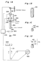
- an optical fiber preform 100 is prepared.
- the optical fiber preform 100 is fabricated by the vapor-phase axial deposition method (VAD method), the outside vapor phase deposition method (OVD method), the modified chemical vapor deposition method (MCVD method), or the rod-in-tube method.
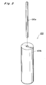
- the fiber preform of this embodiment was fabricated by the rod-in-tube method shown in Fig. 2. More specifically, a hole is formed in a cladding material 100b, and a core material 100a is inserted into the hole, thereby fabricating the preform 100.
- the noncircularity (%) of the core material 10a is 1% or less.
- the noncircularity of the core material is
- Noncircularity (%) (Dmax - Dmin)/Dmax x 100 where Dmax is the maximum value of the diameter of the core material 100a, and Dmin is the minimum value of the diameter of the core material 100a.
- the drawn optical fiber 150 passes through a reaction tube 400 for forming a carbon film.
- a gas containing CHCl3 and C2H4 is supplied into the reaction tube 250.
- the CHCl3 and C2H4 in the gas are reacted on the surface of the optical fiber 150. Carbon sticks to the surface of the optical fiber to form a carbon film 151.
- the optical fiber 150 executes a spindle-like motion in the reaction tube 250, the carbon film 151 with a high uniformity is formed.
- the outer diameter of an optical fiber 160 coated with carbon is measured by a laser outer diameter measurement device 300.
- the resultant optical fiber 100 is formed into not a linear shape but a spindle-like shape.
- the laser outer diameter measurement device 300 has a measurable area allowing outer diameter measurement even when the position of the target measurement object is changed by the motion of the optical fiber 160.
- the measurable area is 5 mm2.
- the necessary measurable area depends on the set position of the laser outer diameter measurement device, though it is normally appropriately selected from a range of 1 to 9 mm2.
- the measurement result is informed to a drawing control unit 400.
- the drawing control unit 400 controls the heating temperature or the drawing speed on the basis of the measured value such that the outer diameter has a predetermined value (normally, 125 ⁇ m).
- the optical fiber 160 passing through the laser outer diameter measurement device passes through a liquid resin 510 stored in a resin coating die 500.
- the resin sticks to the surface of the optical fiber 160 passing through the liquid resin 510.
- An optical fiber 170 with the resin passes through the irradiation region of a UV lamp 600 to cure the resin and yields a resin-coated optical fiber 180.
- the resin-coated optical fiber 180 is wound on a drum 700.
- the distortion in the sectional structure of the optical fiber uniformly appears in all directions of 360° at a predetermined length. Therefore, the entire long optical fiber can equivalently be regarded as an optical transmission line having a round and concentric structure.
- PMD (0) polarization mode dispersion (ps/km 1/2 ) when the nuber of turns is 0
- B birefringence of the optical fiber (nondimensional)
- ⁇ wavelength of light (km)
- PMD B/C
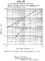
- Figs. 7A to 7D are graphs showing the values PMD obtained in accordance with equation (1). As is apparent from these graphs, when the core noncircularity is 1% or less, and the number of turns per unit length is set to 3 turns per meter or more, the value PMD can be set to 0.5 ps/km 1/2 or less.
- a dispersion compensation fiber twisted at a rate of 1 to 20 turns per meter is applicable for the optical transmission system of Fig. 3.
- a dispersion compensation fiber comprised of a material comprising either one of AlF3, ZrF4 and HfF4, and twisted at a rate of 1 to 20 turns per meter is applicable for the system of Fig. 3.
- Fig. 4 is a graph showing the relationship between the rotational speed (rpm) of the optical fiber preform and variations in outer diameter of the optical fiber ( ⁇ m). This graph was obtained as a result of an experiment by the present inventors. Conditions for this experiment were as follows. Material of preform: quarts glass (silica glass) Outer diameter of preform 100: 36 mm GeO2 concentration in core 100a: 10 mol% Drawing speed: 100 m/min Drawing tension: 6.5 kg/mm2 (corresponding to an applied tension of 80 g for a completed fiber with a diameter of 125 ⁇ m) The shape of the preform and the concentration of the dopant match those of the fiber fabricated from this preform. Fig.
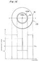
- 1E is a view showing the cross section of the fabricated optical fiber and the refractive index profile thereof.
- the diameter of a core 1100a is 5 ⁇ m.
- the diameter of a cladding 1100b is 125 ⁇ m.
- the thickness of the carbon film 151 is 300 ⁇ .
- the thickness of the resin is 58 ⁇ m.
- the diameter of the core 1100a may also be 2 ⁇ m to 6 ⁇ m.
- the diameter of the cladding 1100b may also be 122 to 128 ⁇ m.
- the thickness of the carbon film 151 may also be 100 to 1000 ⁇ .
- the thickness of the resin may also be 20 to 70 ⁇ m.
- the GeO2 concentration of the core 1100a is 10 mol%. However, it may also be 7mol/% to 30 mol%.
- the F concentration of the cladding 1100b is 0.5 wt%. However, it also may also be 0.1 wt% to 1 wt%.
- Variations in outer diameter of the optical fiber is associated with a transmission loss. As the variations in outer diameter become smaller, the transmission loss also becomes smaller. In an optical fiber having a diameter of 125 ⁇ m for practical use, the variations in outer diameter preferably fall within a range of about ⁇ 3 ⁇ m. As is apparent from the graph of Fig. 4, when the rotational speed is 10 to 1,000 rpm, the variations in outer diameter fall within a range of about ⁇ 3 ⁇ m.
- Fig. 5 is a graph showing the relationship between the drawing tension applied to the optical fiber preform and variations in outer diameter of the optical fiber. This graph was obtained as a result of an experiment by the present inventors. Conditions for the experiment are as follows.
- the drawing tension is preferably set to 2.4 to 13 kg/mm2.
- the reason for this is as follows. That is, at a drawing tension of 2.4 kg/mm2 or less, the final outer diameter becomes unstable because of a large whirling of the resultant optical fiber. At a drawing tension of 13 kg/mm2 or more, breaking of the optical fiber usually occurs. At a drawing tension of 16 kg/mm2 or more, the optical fiber is always broken.
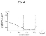
- Fig. 6 is a graph showing the relationship between the drawing speed of the optical fiber and variations in outer diameter of the optical fiber. This graph was obtained as a result of an experiment by the present inventors. Conditions for the experiment are as follows: Material of preform: quartz glass (silica glass) Outer diameter of preform 100: 36 mm GeO2 concentration in core 100a: 10 mol% Rotational speed: 300 rpm Drawing tension: 10 kg/mm2 As is apparent from the graph of Fig. 6, to minimize the variations in outer diameter, the drawing speed is preferably set to 50 to 1,000 m/min.
- A-13 A-14 A-15 A-16 Fiber structure Profile type A A A A ⁇ + (%) 2.6 2.6 0.8 0.8 ⁇ (%) 0.36 0 0 0 0 Ra - - - - 2Da ( ⁇ m) 2.2 2.2 5.0 5.0 Drawing Rotational speed (r/min) 0 300 0 300 Drawing speed (m/min) 100 100 100 100 Drawing tension (kg/mm2) 13 13 13 13 13 Characteristics Variations in fiber diameter ( ⁇ m) ⁇ 0.2 ⁇ 0.2 ⁇ 0.1 ⁇ 0.2 Polarization mode dispersion (ps/km 1/2 ) 30 0.1 0.12 0.008 Dispersion value (ps/km/nm) -95 -95 +1 +1 Dispersion slope (ps/km/nm2) +0.09 +0.09 +0.08 +0.08 Transmission loss (dB/km) 0.38 0.9 0.21 0.21 Figure of merit (ps/nm/dB) 250 106 x x Preform core noncircularity (%) 1.0 0.35 0.35 0.35 Table
- A-17 A-18 Fiber structure Profile type A A ⁇ + (%) 0.8 0.4 ⁇ (%) 0 0 Ra - - 2Da ( ⁇ m) 10.0 10.0 Drawing Rotational speed (r/min) 0 300 Drawing speed (m/min) 100 100 Drawing tension (kg/mm2) 13 13 Characteristics Variations in fiber diameter ( ⁇ m) ⁇ 0.1 ⁇ 0.2 Polarization mode dispersion (ps/km 1/2 ) 0.15 0.006 Dispersion value (ps/km/nm) +17 +17 Dispersion slope (ps/km/nm2) +0.06 +0.06 Transmission loss (dB/km) 0.19 0.19 Figure of merit (ps/nm/dB) x x Preform core noncircularity (%) 0.38 0.38
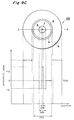
- FIG. 9A A fabricating apparatus shown in Fig. 9A is the same as that shown in Fig. 1A.
- Fig. 9B is a view showing an optical fiber preform 800 set in this apparatus.
- the preform 800 is fabricated by the rod-in-tube method shown in Figs. 9D and 9E.
- a cylindrical rod for core 13 and a cylindrical rod for first cladding 11 are fabricated by the VAD method.
- the core rod 13 is silica glass doped with GeO2.
- a doping amount of GeO2 is adjusted so that the refractive index decreases in proportion to the second power to the fifth power of distance toward the periphery from the center.
- the refractive index in the core rod 13 may be arranged to decrease stepwise with an increase of distance away from the center.
- the first cladding 11 is silica glass uniformly doped with fluorine.
- the first cladding rod 11 is perforated to form a hole 11h for inserting the core rod 13 thereinto. Then the core rod 13 is inserted into the hole 11h.
- a cylindrical rod for second cladding 12 is fabricated by the VAD method.
- the second cladding rod 12 is pure silica glass.
- the second cladding rod 12 is perforated to form a hole 12h for inserting the first cladding rod 11 thereinto.
- the first cladding rod 11 with the core rod 13 therein is inserted into the hole 12h, and the combination is heated to complete a preform 800.
- This preform 800 is drawn using the apparatus shown in Fig. 9A to produce a fiber 103.
- One end of the preform 800 is heated by a heater 230, so that the one end is fused.
- the fused one end of the preform 800 is cooled to yield an optical fiber.
- the optical fiber is wound around a take-up reel (bobbin) 700 via a pulley PL1.
- a glass fiber drawn from the preform 800 is coated with a carbon film 4 by a carbon coat apparatus 250.
- the carbon film 4 is coated with a jacket material (resin film) 5.
- the optical fiber shown in Fig. 9C is the optical fiber 103 rolled around the take-up reel 700 in Fig. 9A.
- the refractive index of the resin film 5 is higher than that of the second cladding.
- This dispersion compensation fiber is a "double-cladding" fiber.
- This dispersion compensation optical fiber is provided with a core 3, a first cladding 1 surrounding the core 3, a second cladding 2 surrounding the first cladding 1, the carbon coating 4, and the resin coat 5 surrounding the second cladding 2.
- the refractive index of the second cladding 2 is lower than that of the core but higher than that of the first cladding.
- the refractive index of the core 3 is nc, that of the first cladding 1 n1, and that of the second cladding 2 n2
- a refractive index n5 of the resin 5 is higher than that of the second cladding 2 and higher than that of the core 3.
- the diameter (2Da) of the core 3 is larger than 2 ⁇ m but smaller than 4 ⁇ m.
- a specific refractive index difference of the first cladding 1 to the second cladding 2, ⁇ (n2 - n1)/n2 , is larger than 0.004 but smaller than 0.01.
- a bending loss L bend of this fiber at the wavelength 1.55 ⁇ m with a bending diameter 2R (where R is a radius of curvature of dispersion compensation fiber) being lower than 40 mm is below 0.01 dB/m.
- the outer diameter (2Dc) of the second cladding 2 is 125 ⁇ m.
- the diameter (2Da) of the core 3 in the dispersion compensation fiber is between 2.4 ⁇ m and 3.2 ⁇ m both inclusive of 2Dc. This is smaller than the core diameter of the conventional single-mode fiber (10 ⁇ m of 2Dc).
- Fig. 3 shows an optical transmission system using the above dispersion compensation fiber.
- This system is provided with a light source 10, a transmission link 101 for connecting the light source to a fiber amplifier 102, a dispersion compensation fiber 103 connected to the erbium-doped fiber 102 and wound around a bobbin 106, a band-pass filter 104 connected to the dispersion compensation fiber 103, and a detector 105 connected to the band-pass filter 104.
- the transmission link 101 is a single-mode optical fiber 101 having zero dispersion at a predetermined wavelength between 1,290 nm and 1,330 nm, for example at 1,310 nm.
- the radius of curvature R of the dispersion compensation fiber 103 thus wound is between 20 mm and 40 mm both inclusive.
- the bending diameter 2R is between 40 mm and 80 mm both inclusive.
- the elements other than the dispersion compensation fiber in this system are described in European Laid-Open Patent Application No. 0554714A1. Note that a fiber 170 may also be used in place of the dispersion compensation fiber 103.
- the present invention is not limited to the above embodiments, and various changes and modifications can also be made.
- the core is highly doped with GeO2.
- the core may also be doped with any dopant other than Ge, and the dopant concentration is not limited. Even with an optical fiber having a doped cladding, the same effect as described above can be obtained according to the same fabricating method.
- the optical fiber is fabricated by rotation drawing with appropriate control amounts (rotational speed, drawing speed, and drawing tension). For this reason, even when the optical fiber or the core has no completely round and concentric structure, an optical fiber capable of equivalently suppressing polarization mode dispersion caused due to the noncircularity can be stably fabricated.
- a reaction tube for forming a carbon film is arranged in a region where the optical fiber executes a spindle-like motion to form a carbon film on the optical fiber, a carbon film with a high uniformity can be formed. Therefore, a high-quality optical fiber having a high resistance to environment and free from variations in outer diameter can be fabricated.
Landscapes
- Chemical & Material Sciences (AREA)
- Physics & Mathematics (AREA)
- Dispersion Chemistry (AREA)
- Optics & Photonics (AREA)
- General Physics & Mathematics (AREA)
- Engineering & Computer Science (AREA)
- Life Sciences & Earth Sciences (AREA)
- Geochemistry & Mineralogy (AREA)
- Materials Engineering (AREA)
- Organic Chemistry (AREA)
- General Life Sciences & Earth Sciences (AREA)
- Chemical Kinetics & Catalysis (AREA)
- General Chemical & Material Sciences (AREA)
- Manufacturing & Machinery (AREA)
- Manufacture, Treatment Of Glass Fibers (AREA)
- Glass Compositions (AREA)
- Optical Fibers, Optical Fiber Cores, And Optical Fiber Bundles (AREA)
Applications Claiming Priority (3)
| Application Number | Priority Date | Filing Date | Title |
|---|---|---|---|
| JP20209194A JP3491644B2 (ja) | 1994-08-26 | 1994-08-26 | 光ファイバの製造方法 |
| JP20209194 | 1994-08-26 | ||
| JP202091/94 | 1994-08-26 |
Publications (3)
| Publication Number | Publication Date |
|---|---|
| EP0698582A2 true EP0698582A2 (fr) | 1996-02-28 |
| EP0698582A3 EP0698582A3 (fr) | 1996-11-13 |
| EP0698582B1 EP0698582B1 (fr) | 1999-11-17 |
Family
ID=16451823
Family Applications (1)
| Application Number | Title | Priority Date | Filing Date |
|---|---|---|---|
| EP95113381A Expired - Lifetime EP0698582B1 (fr) | 1994-08-26 | 1995-08-25 | Procédé de fabrication d'une fibre de verre pour compenser la dispersion chromatique et un système de transmission optique incorporant la fibre. |
Country Status (4)
| Country | Link |
|---|---|
| US (1) | US5581647A (fr) |
| EP (1) | EP0698582B1 (fr) |
| JP (1) | JP3491644B2 (fr) |
| DE (1) | DE69513344T2 (fr) |
Cited By (6)
| Publication number | Priority date | Publication date | Assignee | Title |
|---|---|---|---|---|
| EP1129999A3 (fr) * | 2000-02-29 | 2001-11-21 | Lucent Technologies Inc. | Procédé de fabrication de préformes à plusieres gaines pour fibres optiques |
| US6789399B1 (en) | 1999-05-14 | 2004-09-14 | Fujikura Ltd. | Method for measuring the twisting of an optical fiber, and a method and apparatus for manufacturing optical fibers |
| EP1571133A1 (fr) * | 2004-03-01 | 2005-09-07 | Furukawa Electric North America Inc. | Procédé et dispositif pour la fabrication de fibres optiques avec rotation des préformes pendant l'étirage |
| EP2407436A1 (fr) * | 2010-07-15 | 2012-01-18 | Sumitomo Electric Industries, Ltd. | Fibre optique et procédé de fabrication correspondant |
| US8265431B2 (en) | 2009-11-06 | 2012-09-11 | Baker Hughes Incorporated | Rotated single or multicore optical fiber |
| US8385692B2 (en) | 2009-05-27 | 2013-02-26 | Baker Hughes Incorporated | On-line fiber Bragg grating dithering |
Families Citing this family (42)
| Publication number | Priority date | Publication date | Assignee | Title |
|---|---|---|---|---|
| BR9506216A (pt) * | 1994-04-25 | 1997-09-30 | Furukawa Electric Co Ltd | Pré-forma fibra óptica e processo de produção de fibra óptica |
| JPH09211249A (ja) * | 1995-11-28 | 1997-08-15 | Sumitomo Electric Ind Ltd | シングルモード光ファイバ |
| US5802234A (en) * | 1997-03-21 | 1998-09-01 | Lucent Technologies, Inc | Dispersion compensating optical fiber, and communication system comprising same |
| FR2790107B1 (fr) * | 1999-02-18 | 2001-05-04 | Cit Alcatel | Fibre de ligne pour systemes de transmission a fibre optique a multiplexage en longueurs d'onde |
| US6233387B1 (en) * | 1998-11-30 | 2001-05-15 | Corning Incorporated | Broadband pulse-reshaping optical fiber |
| WO2000064824A2 (fr) * | 1999-04-26 | 2000-11-02 | Corning Incorporated | Fibre optique et procede de fabrication de fibre optique a faible dispersion de mode-polarisation et a faible attenuation |
| BR0010173A (pt) | 1999-04-30 | 2002-01-15 | Corning Inc | Fibra de compensação de dispersão |
| US6427044B1 (en) | 1999-06-23 | 2002-07-30 | Sumitomo Electric Industries, Ltd. | Optical fiber |
| US6453102B1 (en) | 2000-02-07 | 2002-09-17 | Corning Incorporated | Dispersion compensating module and mode converter, coupler and dispersion compensating optical waveguide therein |
| US6445864B2 (en) | 2000-03-24 | 2002-09-03 | Corning Incorporated | Dispersion compensating optical fiber |
| US6650814B2 (en) | 2001-12-11 | 2003-11-18 | Corning Incorporated | Single mode dispersion compensating optical fiber |
| US6735985B2 (en) * | 2001-12-20 | 2004-05-18 | Furukawa Electric North America Inc | Method of impressing a twist on a multimode fiber during drawing |
| KR100401342B1 (en) * | 2002-08-31 | 2003-10-10 | Lg Cable Ltd | Apparatus for spinning optical fiber and apparatus and method for fabricating optical fiber using the same |
| WO2004050573A1 (fr) * | 2002-09-25 | 2004-06-17 | Giacomo Stefano Roba | Procede de production d'une fibre optique ayant une faible dispersion de polarisation de mode |
| KR100512592B1 (ko) * | 2002-10-22 | 2005-09-07 | 엘에스전선 주식회사 | 광섬유 모재 회전을 통해 광섬유 진원도를 개선하는광섬유 인선 장치 및 이를 이용한 광섬유 인선 방법 |
| WO2004095098A1 (fr) * | 2003-03-27 | 2004-11-04 | Corning Incorporated | Fibre optique de compensation de dispersion de bande large de haute dispersion |
| US20050185877A1 (en) * | 2004-02-12 | 2005-08-25 | Panorama Flat Ltd. | Apparatus, Method, and Computer Program Product For Structured Waveguide Switching Matrix |
| US7254287B2 (en) * | 2004-02-12 | 2007-08-07 | Panorama Labs, Pty Ltd. | Apparatus, method, and computer program product for transverse waveguided display system |
| US7224854B2 (en) | 2004-02-12 | 2007-05-29 | Panorama Labs Pty. Ltd. | System, method, and computer program product for structured waveguide including polarizer region |
| US20050180673A1 (en) * | 2004-02-12 | 2005-08-18 | Panorama Flat Ltd. | Faraday structured waveguide |
| US20050180674A1 (en) * | 2004-02-12 | 2005-08-18 | Panorama Flat Ltd. | Faraday structured waveguide display |
| US20050180723A1 (en) * | 2004-02-12 | 2005-08-18 | Panorama Flat Ltd. | Apparatus, method, and computer program product for structured waveguide including holding bounding region |
| US20060056793A1 (en) * | 2004-02-12 | 2006-03-16 | Panorama Flat Ltd. | System, method, and computer program product for structured waveguide including nonlinear effects |
| US20060056794A1 (en) * | 2004-02-12 | 2006-03-16 | Panorama Flat Ltd. | System, method, and computer program product for componentized displays using structured waveguides |
| US20050180675A1 (en) * | 2004-02-12 | 2005-08-18 | Panorama Flat Limited, A Western Australia Corporation | Apparatus, method, and computer program product for structured waveguide including performance_enhancing bounding region |
| US20050180672A1 (en) * | 2004-02-12 | 2005-08-18 | Panorama Flat Ltd. | Apparatus, Method, and Computer Program Product For Multicolor Structured Waveguide |
| US20060056792A1 (en) * | 2004-02-12 | 2006-03-16 | Panorama Flat Ltd. | System, method, and computer program product for structured waveguide including intra/inter contacting regions |
| US8057567B2 (en) | 2004-11-05 | 2011-11-15 | Donaldson Company, Inc. | Filter medium and breather filter structure |
| US8021457B2 (en) | 2004-11-05 | 2011-09-20 | Donaldson Company, Inc. | Filter media and structure |
| ES2772198T3 (es) | 2004-11-05 | 2020-07-07 | Donaldson Co Inc | Medio y estructura de filtro |
| US12172111B2 (en) | 2004-11-05 | 2024-12-24 | Donaldson Company, Inc. | Filter medium and breather filter structure |
| BRPI0606842A2 (pt) | 2005-02-04 | 2009-07-21 | Donaldson Co Inc | separador de aerossol |
| CN101163534A (zh) | 2005-02-22 | 2008-04-16 | 唐纳森公司 | 气溶胶分离器 |
| WO2007122630A2 (fr) * | 2006-04-24 | 2007-11-01 | Sterlite Optical Technologies Ltd. | Fibre optique monomode à perte de macrocourbure et d'atténuation réduites et procédé de fabrication de celle-ci |
| JPWO2008007743A1 (ja) * | 2006-07-12 | 2009-12-10 | 古河電気工業株式会社 | 偏波保持光ファイバおよび偏波保持光ファイバ接続体の製造方法ならびに偏波保持光ファイバ接続体 |
| MX2009009046A (es) | 2007-02-22 | 2009-10-14 | Donaldson Co Inc | Metodo y elemento para filtro. |
| WO2008103821A2 (fr) | 2007-02-23 | 2008-08-28 | Donaldson Company, Inc. | Élément de filtre formé |
| US9885154B2 (en) | 2009-01-28 | 2018-02-06 | Donaldson Company, Inc. | Fibrous media |
| JP6031838B2 (ja) | 2012-06-08 | 2016-11-24 | 住友電気工業株式会社 | 光ファイバの製造方法 |
| US9162918B2 (en) * | 2013-02-13 | 2015-10-20 | Ofs Fitel, Llc | Method and apparatus for clamping a spinning preform and reducing the vibration of twisted optical fiber from a spinning preform |
| JP6252652B2 (ja) * | 2016-10-26 | 2017-12-27 | 住友電気工業株式会社 | 光ファイバの製造方法 |
| CN111302642A (zh) * | 2020-04-17 | 2020-06-19 | 安徽丹凤集团桐城玻璃纤维有限公司 | 一种电子纱及其生产方法 |
Citations (2)
| Publication number | Priority date | Publication date | Assignee | Title |
|---|---|---|---|---|
| JPH02101767A (ja) | 1988-10-11 | 1990-04-13 | Agency Of Ind Science & Technol | 半導体装置 |
| US5361319A (en) | 1992-02-04 | 1994-11-01 | Corning Incorporated | Dispersion compensating devices and systems |
Family Cites Families (11)
| Publication number | Priority date | Publication date | Assignee | Title |
|---|---|---|---|---|
| GB2101762B (en) * | 1981-07-07 | 1984-11-28 | Central Electr Generat Board | Optic fibre |
| US4473273A (en) * | 1981-09-04 | 1984-09-25 | Trw Inc. | High bandwidth fiber and method of forming the same by preform rotation during drawing |
| FR2537608B2 (fr) * | 1982-12-10 | 1985-12-27 | Thomson Csf | Dispositif de fabrication d'un objet a structure chiralique a partir d'une source de matiere formable |
| JPS63208003A (ja) * | 1987-02-25 | 1988-08-29 | Sumitomo Electric Ind Ltd | 光フアイバ |
| JP2636876B2 (ja) * | 1988-04-08 | 1997-07-30 | 日本電信電話株式会社 | 光ファイバの分散補償装置 |
| US5298047A (en) * | 1992-08-03 | 1994-03-29 | At&T Bell Laboratories | Method of making a fiber having low polarization mode dispersion due to a permanent spin |
| JP2760233B2 (ja) * | 1992-09-29 | 1998-05-28 | 住友電気工業株式会社 | 光通信装置 |
| US5448674A (en) * | 1992-11-18 | 1995-09-05 | At&T Corp. | Article comprising a dispersion-compensating optical waveguide |
| SE501932C2 (sv) * | 1993-04-30 | 1995-06-26 | Ericsson Telefon Ab L M | Anordning och förfarande för dispersionskompensering i ett fiberoptiskt transmissionssystem |
| AU670505B2 (en) * | 1993-06-22 | 1996-07-18 | Sumitomo Electric Industries, Ltd. | Optical fiber preform, optical fiber and their manufacturing methods |
| US5473719A (en) * | 1993-11-15 | 1995-12-05 | At&T Corp. | Optical dispersion compensator |
-
1994
- 1994-08-26 JP JP20209194A patent/JP3491644B2/ja not_active Expired - Fee Related
-
1995
- 1995-08-25 EP EP95113381A patent/EP0698582B1/fr not_active Expired - Lifetime
- 1995-08-25 DE DE69513344T patent/DE69513344T2/de not_active Expired - Fee Related
- 1995-08-25 US US08/519,609 patent/US5581647A/en not_active Expired - Lifetime
Patent Citations (2)
| Publication number | Priority date | Publication date | Assignee | Title |
|---|---|---|---|---|
| JPH02101767A (ja) | 1988-10-11 | 1990-04-13 | Agency Of Ind Science & Technol | 半導体装置 |
| US5361319A (en) | 1992-02-04 | 1994-11-01 | Corning Incorporated | Dispersion compensating devices and systems |
Cited By (7)
| Publication number | Priority date | Publication date | Assignee | Title |
|---|---|---|---|---|
| US6789399B1 (en) | 1999-05-14 | 2004-09-14 | Fujikura Ltd. | Method for measuring the twisting of an optical fiber, and a method and apparatus for manufacturing optical fibers |
| EP1129999A3 (fr) * | 2000-02-29 | 2001-11-21 | Lucent Technologies Inc. | Procédé de fabrication de préformes à plusieres gaines pour fibres optiques |
| EP1571133A1 (fr) * | 2004-03-01 | 2005-09-07 | Furukawa Electric North America Inc. | Procédé et dispositif pour la fabrication de fibres optiques avec rotation des préformes pendant l'étirage |
| US8385692B2 (en) | 2009-05-27 | 2013-02-26 | Baker Hughes Incorporated | On-line fiber Bragg grating dithering |
| US8265431B2 (en) | 2009-11-06 | 2012-09-11 | Baker Hughes Incorporated | Rotated single or multicore optical fiber |
| US8630515B2 (en) | 2009-11-06 | 2014-01-14 | Baker Hughes Incorporated | Rotated single or multicore optical fiber |
| EP2407436A1 (fr) * | 2010-07-15 | 2012-01-18 | Sumitomo Electric Industries, Ltd. | Fibre optique et procédé de fabrication correspondant |
Also Published As
| Publication number | Publication date |
|---|---|
| EP0698582B1 (fr) | 1999-11-17 |
| DE69513344D1 (de) | 1999-12-23 |
| JP3491644B2 (ja) | 2004-01-26 |
| EP0698582A3 (fr) | 1996-11-13 |
| JPH0859278A (ja) | 1996-03-05 |
| DE69513344T2 (de) | 2000-04-20 |
| US5581647A (en) | 1996-12-03 |
Similar Documents
| Publication | Publication Date | Title |
|---|---|---|
| US5581647A (en) | Method of fabricating dispersion compensation fiber | |
| US4896942A (en) | Polarization-maintaining optical fiber | |
| US9796618B2 (en) | Multi-core optical fiber ribbons and methods for making the same | |
| US7844155B2 (en) | Optical fiber containing alkali metal oxide | |
| US4447127A (en) | Low loss single mode fiber | |
| EP0294037B1 (fr) | Atténuateur à fibres optiques | |
| US8230702B2 (en) | Glass-tube extended-baking process | |
| JP3653724B2 (ja) | 光ファイバ、及びその製造方法 | |
| US20100067859A1 (en) | Single Mode Optical Fiber | |
| JPS6113203A (ja) | 単一モード光学繊維 | |
| US6567597B2 (en) | Optical fiber, method of making the same, and optical transmission system including the same | |
| US5251277A (en) | Optical fiber coupler exhibiting reduced polarization sensitivity and method of making same | |
| EP0630865A1 (fr) | Fibre optique et préforme et procédés pour leur fabrication | |
| AU674728B2 (en) | Partially detached core optical waveguide | |
| GB2096788A (en) | Single polarization single-mode optical fibers | |
| US4747663A (en) | Monomode quartz glass light waveguide and method for producing it | |
| Niizeki | Recent progress in glass fibers for optical communication | |
| US20020000104A1 (en) | Methods of making preform and optical fiber | |
| US7849713B2 (en) | Optical fibre having low splice loss and method for making it | |
| EP0185975A1 (fr) | Procédé de fabrication d'une préforme en verre | |
| CN102096146A (zh) | 高负色散光纤、制造方法及色散补偿模块 | |
| Ghigo et al. | GeO [sub] 2 [/sub] Doped High NA Multimode Fibre Made By Pressurized MCVD | |
| JP2001066453A (ja) | 光ファイバ | |
| Adams et al. | Introduction to Optical Fibres | |
| HK1086338B (en) | Optical fibre having low splice loss and method for making it |
Legal Events
| Date | Code | Title | Description |
|---|---|---|---|
| PUAI | Public reference made under article 153(3) epc to a published international application that has entered the european phase |
Free format text: ORIGINAL CODE: 0009012 |
|
| AK | Designated contracting states |
Kind code of ref document: A2 Designated state(s): DE FR GB IT SE |
|
| RIN1 | Information on inventor provided before grant (corrected) |
Inventor name: KANAMORI, HIROO, C/O YOKOHAMA WORKS Inventor name: FUKUDA, CHIE, C/O YOKOHAMA WORKS Inventor name: AMEMIYA, KOJI, C/O YOKOHAMA WORKS Inventor name: ONISHI, MASASHI, C/O YOKOHAMA WORKS |
|
| PUAL | Search report despatched |
Free format text: ORIGINAL CODE: 0009013 |
|
| AK | Designated contracting states |
Kind code of ref document: A3 Designated state(s): DE FR GB IT SE |
|
| 17P | Request for examination filed |
Effective date: 19961220 |
|
| 17Q | First examination report despatched |
Effective date: 19970128 |
|
| GRAG | Despatch of communication of intention to grant |
Free format text: ORIGINAL CODE: EPIDOS AGRA |
|
| GRAG | Despatch of communication of intention to grant |
Free format text: ORIGINAL CODE: EPIDOS AGRA |
|
| GRAG | Despatch of communication of intention to grant |
Free format text: ORIGINAL CODE: EPIDOS AGRA |
|
| GRAH | Despatch of communication of intention to grant a patent |
Free format text: ORIGINAL CODE: EPIDOS IGRA |
|
| GRAH | Despatch of communication of intention to grant a patent |
Free format text: ORIGINAL CODE: EPIDOS IGRA |
|
| GRAH | Despatch of communication of intention to grant a patent |
Free format text: ORIGINAL CODE: EPIDOS IGRA |
|
| GRAA | (expected) grant |
Free format text: ORIGINAL CODE: 0009210 |
|
| AK | Designated contracting states |
Kind code of ref document: B1 Designated state(s): DE FR GB IT SE |
|
| ITF | It: translation for a ep patent filed | ||
| REF | Corresponds to: |
Ref document number: 69513344 Country of ref document: DE Date of ref document: 19991223 |
|
| ET | Fr: translation filed | ||
| PLBE | No opposition filed within time limit |
Free format text: ORIGINAL CODE: 0009261 |
|
| STAA | Information on the status of an ep patent application or granted ep patent |
Free format text: STATUS: NO OPPOSITION FILED WITHIN TIME LIMIT |
|
| 26N | No opposition filed | ||
| REG | Reference to a national code |
Ref country code: GB Ref legal event code: IF02 |
|
| PGFP | Annual fee paid to national office [announced via postgrant information from national office to epo] |
Ref country code: GB Payment date: 20020821 Year of fee payment: 8 |
|
| PGFP | Annual fee paid to national office [announced via postgrant information from national office to epo] |
Ref country code: DE Payment date: 20020829 Year of fee payment: 8 |
|
| PGFP | Annual fee paid to national office [announced via postgrant information from national office to epo] |
Ref country code: SE Payment date: 20030806 Year of fee payment: 9 |
|
| PG25 | Lapsed in a contracting state [announced via postgrant information from national office to epo] |
Ref country code: GB Free format text: LAPSE BECAUSE OF NON-PAYMENT OF DUE FEES Effective date: 20030825 |
|
| PG25 | Lapsed in a contracting state [announced via postgrant information from national office to epo] |
Ref country code: DE Free format text: LAPSE BECAUSE OF NON-PAYMENT OF DUE FEES Effective date: 20040302 |
|
| GBPC | Gb: european patent ceased through non-payment of renewal fee | ||
| PG25 | Lapsed in a contracting state [announced via postgrant information from national office to epo] |
Ref country code: SE Free format text: LAPSE BECAUSE OF NON-PAYMENT OF DUE FEES Effective date: 20040826 |
|
| EUG | Se: european patent has lapsed | ||
| PGFP | Annual fee paid to national office [announced via postgrant information from national office to epo] |
Ref country code: IT Payment date: 20060831 Year of fee payment: 12 |
|
| PG25 | Lapsed in a contracting state [announced via postgrant information from national office to epo] |
Ref country code: IT Free format text: LAPSE BECAUSE OF NON-PAYMENT OF DUE FEES Effective date: 20070825 |
|
| PGFP | Annual fee paid to national office [announced via postgrant information from national office to epo] |
Ref country code: FR Payment date: 20110818 Year of fee payment: 17 |
|
| REG | Reference to a national code |
Ref country code: FR Ref legal event code: ST Effective date: 20130430 |
|
| PG25 | Lapsed in a contracting state [announced via postgrant information from national office to epo] |
Ref country code: FR Free format text: LAPSE BECAUSE OF NON-PAYMENT OF DUE FEES Effective date: 20120831 |